1. Introduction
Centrifugal compressors are critical turbomachines extensively used in oil and gas, petrochemical, and power generation sectors to compress gases to high pressures. Their functionality hinges on the transformation of kinetic energy—imparted by a rotating impeller—into pressure energy through a diffuser. Among the various configurations, MAN Turbo barrel-type compressors stand out due to their high efficiency, modular design, and capability to handle discharge pressures up to 800 bar and flow rates exceeding 200,000 m
3/h. These compressors are typically delivered as integrated skid packages, complete with auxiliary systems such as lubrication, seal gas, and process piping [
1].
Despite their robust engineering, centrifugal compressors are susceptible to performance degradation, primarily due to vibration and mechanical wear. A frequent root cause of such issues is strainer blockage, which occurs upstream and restricts suction flow. Strainers are designed to filter out contaminants like wax, scale, sand, and metal shavings. However, improper sizing, infrequent cleaning, or corrosion-related debris can lead to clogging, resulting in a drop in inlet pressure. These initiates flow instability and surge conditions, which impose unsteady aerodynamic forces on rotating components—particularly impellers and journal bearings—leading to elevated vibration and accelerated wear.
Recent research has underscored the importance of early fault detection in centrifugal compressors, especially in journal bearings highly sensitive to vibration-induced stress. For instance, Hemati et al developed a hybrid machine learning model combining Support Vector Machines (SVM) and Random Forest, achieving 98.9% accuracy in predicting journal bearing failures. Their study identified pressure fluctuations in suction and discharge lines as key contributors to stress-induced deformation. Similarly, Noor and Eckert linked vibration issues to pulsations, blade passing frequencies, and acoustic resonance, showing that operation away from the best efficiency point significantly increases mechanical fatigue . Garcia-Hernandez et al. further demonstrated how variations in inlet gas composition—such as specific gravity and hydrocarbon content—can alter flow dynamics and exacerbate fouling risks .
While these studies provide valuable insights into vibration diagnostics and operational deviations, a critical gap remains in connecting upstream strainer blockage to downstream mechanical failures. Existing literature often treats aerodynamic instabilities and bearing wear in isolation, lacking integration of field inspection data, chemical analysis of deposits, and operational parameter deviations. Moreover, preventive maintenance strategies—such as chemical cleaning—are rarely compared to traditional methods like overhaul or water jet cleaning [
2,
3,
4].
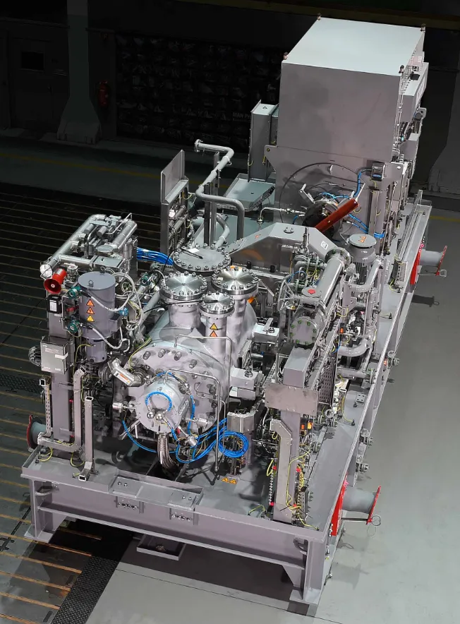
This article aims to bridge that gap by examining the cascading effects of strainer blockage on compressor performance and mechanical integrity, focusing on MAN Turbo barrel-type compressors. () The research methodology involves field data collection, chemical analysis of strainer deposits, and vibration monitoring across multiple operational scenarios. Section 1 outlines the key design parameters of the compressors under study. Section 2 details the research methodology, including instrumentation and data acquisition techniques. Sections 3 and 4 presents the results, followed by a discussion in Section 5 that interprets the findings in the context of existing literature. Finally, Last section concludes with recommendations for predictive maintenance and future research directions, supported by a comprehensive list of references.
. MAN Turbo-Barrel compressor package (MAN turbo official site-Operation manual).
By understanding the full chain of causality—from flow contamination to mechanical degradation—this study provides a foundation for more proactive, data-driven maintenance strategies that enhance compressor reliability, reduce downtime, and extend equipment lifespan.
Compressor Operation Parameters and Design
MAN Turbo barrel-type centrifugal compressors are designed for high-pressure, high-flow applications in oil and gas, petrochemical, and power generation sectors. Their multi-stage, single-shaft configuration with forged barrel-type casings supports pressures up to 800 bar and flow rates exceeding 230,000 m
3/h. For efficient maintenance, key features include dry gas seals, tilting pad bearings, and removable cartridges. Integrated monitoring systems and optional configurations support sour gas, CO
2, and hydrogen service.
Despite their robust design, strainer blockage remains a critical issue. Improper sizing or debris accumulation restricts suction flow, causing inlet pressure drops and triggering surge. This leads to asymmetric aerodynamic forces and frictional imbalance on impellers, increasing vibration and accelerating wear—especially in bronze journal bearings—prolonged exposure results in heating, scoring, and erosion, compromising rotor stability.
Mitigation requires differential pressure monitoring, scheduled cleaning, proper strainer selection, and visual inspections. Real-time condition monitoring enhances early fault detection. Additionally, the first-stage suction cooler, with a 5248.8 m
2 heat transfer area, lowers gas temperature from 74 °C to 38 °C, promoting liquid dropout and improving compression efficiency.
While vibration diagnostics and fault prediction models are advancing, upstream factors like strainer blockage remain underexplored. Existing studies often isolate failure modes and lack integration of field data, deposit analysis, and operational deviations. The impact of gas composition and abnormal conditions on fouling presents a clear gap in compressor reliability research [
2,
3,
4].
The MAN Turbo compression system is supported by a sophisticated control architecture designed to maintain operational stability and protect equipment. Induced draft air coolers with auto-variable blade fans regulate gas outlet temperatures, maintaining 38 °C via temperature controllers that adjust fan speed and blade pitch. If temperatures exceed 65 °C, high-high temperature alarms trigger compressor shutdowns. Vibration monitoring on both fans ensures mechanical protection, with automatic motor shutdowns upon excessive vibration. Cooling performance declines when ambient air temperature exceeds the design threshold of 35 °C.
Gas flow is managed through venturi-type flow meters and pressure transmitters, feeding real-time data to the anti-surge control system. Temporary commissioning strainers and differential pressure indicators support surge prevention and flow stability. Suction pressure is maintained at 0.3 barg via discharge-side modulation, with high-high and low-low pressure trips preventing vacuum conditions and air ingress. The first stage compresses 15.6 MMscfd of hydrocarbon gas from 0.3 to 4.7 barg, discharging at approximately 115 °C.
The second stage suction cooler, with a heat transfer area of 7617.7 m
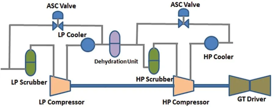
2, cools gas from 100 °C to 38 °C. This stage compresses 30 MMscfd from 2.6 to 13.4 barg, discharging at 140 °C. Overpressure protection is provided via 2oo3 voting logic on pressure transmitters, with blowdown valves sized for settle-out conditions. The second and third stages share a common casing and settle-out pressure via seal leakage. In the event of a motor trip, inlet, outlet, and interstage valves close automatically, while anti-surge recycle valves open to stabilise the system ().
. Multistage compression demonstration.
Instrumentation across stages, including flow, pressure, and temperature transmitters, feeds into the Uninterruptible Power Supply (UCP) for anti-surge control. Maintaining low first-stage suction pressure is essential for meeting oil vapor pressure specifications. The combined discharge pressure from the second and third stages reaches approximately 45 barg.
While recent studies have explored vibration diagnostics and surge control in centrifugal compressors, there remains a critical gap in understanding how upstream flow restrictions—particularly strainer blockage—initiate mechanical degradation. Most existing literature focuses on aerodynamic instabilities or bearing wear in isolation, without integrating field-based inspection data, chemical analysis of deposits, and operational deviations. Furthermore, the role of inlet gas composition, temperature fluctuations, and commissioning strainers in triggering surge and vibration events is underrepresented in current research. In particular, strainer blockage restricts suction flow and introduces uneven pressure distribution and turbulent flow patterns at the impeller inlet. These disturbances generate asymmetric aerodynamic loading and increased frictional resistance on the impeller blades, leading to imbalance forces that amplify vibration and mechanical stress. Over time, this imbalance accelerates wear on rotating components and compromises the dynamic stability of the compressor, especially under high-load conditions [
5,
6,
7].
2. Research Methodology
This study was initiated to investigate recurring operational issues in a MAN Turbo barrel-type centrifugal compressor, specifically frequent blockages in the first-stage suction strainer. These blockages were caused by the accumulation of deposits resulting from hydrogen sulfide (H
2S) scaling and erosion of carbon steel pipelines. The resulting surge events, loss of forward flow, and damage to internal components—particularly bronze journal bearings—prompted a comprehensive diagnostic and analytical approach.
2.1. Problem Identification and Initial Assessment
The compressor system experienced frequent blockages in the first-stage suction strainer due to the accumulation of deposits from H
2S scaling and erosion from carbon steel pipelines. These blockages led to compressor surge, loss of forward flow, and damage to internal parts, particularly the journal bearings, including the bronze components. The presence of H
2S in the gas stream caused significant scaling, while the erosion of carbon steel pipelines contributed to the deposits. The use of carbon steel and bronze components made the system susceptible to corrosion and erosion.
These recurring blockages significantly impacted the reliability, efficiency, and safety of the compressor system, highlighting the need to address the underlying causes of H
2S scaling and erosion.
2.2. Gas Composition and Deposit Analysis
Following the frequent compressor strainer blockages, which had become a routine task for clean-out activities, the engineering team decided to investigate the root cause of these issues. They began by analysing the ingredients of the inlet flashed gas to identify the components contributing to the blockages. This analysis aimed to pinpoint the specific substances causing the H
2S scaling and erosion, which were leading to the accumulation of deposits in the suction strainer.
Samples of the inlet gas were collected at various points in the system and subjected to detailed chemical analysis. The team focused on identifying the presence of H
2S and other corrosive agents that could contribute to scaling and erosion. They also examined the physical characteristics of the deposits found in the strainer, such as their composition, size, and texture.
The analysis revealed that the inlet gas contained high levels of H
2S, which reacted with the carbon steel pipelines to form iron sulfide scales. These scales were brittle and prone to breaking off, leading to the accumulation of deposits in the suction strainer. Additionally, the presence of other corrosive agents, such as carbon dioxide and water vapor, exacerbated the erosion of the carbon steel pipelines, further contributing to the problem.
It was also noted that the operating conditions of the compressor, such as temperature and pressure, played a significant role in the formation and deposition of these scales. High temperatures and pressures accelerated the chemical reactions between H
2S and the pipeline material, increasing the rate of scaling and erosion.
Armed with this information, the engineering team was able to understand better the root causes of the strainer blockages and the associated operational issues. This comprehensive analysis provided valuable insights into the mechanisms driving the problem and laid the groundwork for developing effective solutions to mitigate the impact of H
2S scaling and erosion on the compressor system [
8,
9].
2.3. Visual Inspection and Equipment Evaluation
To validate the chemical findings, a baroscopic inspection was conducted upstream and downstream of the suction strainer, including the carbon steel piping and the casing of the compressor. The inspection revealed significant fouling and scaling within the carbon steel pipelines and the compressor casing. The internal surfaces were coated with iron sulfide scales and other deposits, contributing to frequent blockages and operational issues.
2.4. Vibration and Wear Identification
Special attention was given to identifying the sources of vibration and wear. Vibration monitoring data was analysed using integrated sensors and control system logs. The compressor cartridge was identified as a critical location for imbalance. Excessive vibration levels were correlated with wear patterns observed in journal bearings, particularly those made of bronze.
The methodology for vibration identification included:
Continuous monitoring of vibration amplitude and frequency
Correlation with operating conditions (e.g., pressure, temperature, flow rate)
Shutdown event analysis to trace vibration spikes to specific mechanical faults.
Wear identification was conducted through:
Visual inspection of bearing surfaces
Measurement of scoring, erosion, and deformation
Comparison with baseline specifications and tolerances.
2.5. Root Cause Analysis
The root cause analysis integrated chemical, mechanical, and operational data. It revealed that startup procedures involving Monoethylene Glycol (MEG) contributed to moisture formation, which caused rust in suction scrubbers and pipelines. During startup, dislodged deposits were flushed into the suction strainer, triggering surge and vibration events.
This multi-layer approach allowed the team to isolate the primary drivers of mechanical degradation and propose targeted mitigation strategies.
2.6. Mechanical Stress Evaluation
To quantify the impact of operational loads, a stress-strain analysis was performed using finite element methods (FEM). The shaft and bearing components were evaluated for axial thrust, radial forces, and torque.
Calculating stress and strain in compressor rotating parts is essential for ensuring the safety and integrity of compression systems. Various stresses can act on a compressor, each arising from different sources. Below are the primary stress types and their corresponding formulas:
- 1.
-
Determine the Forces Acting on the Shaft:
Axial Thrust: This is the force exerted along the axis of the shaft due to pressure differences across the impeller.
Radial Forces: These forces act perpendicular to the shaft, often due to an imbalance in the rotating components.
Torque: The rotational force applied to the shaft.
- 2.
-
Calculate the Stress:
Axial Stress:
where F
axial is thrust, and A is the cross-sectional area of the shaft.
Radial Stress:
where F
radial is the radial force.
Torsional Stress:
where T is the torque and J is the polar moment of inertia of the shaft.
Stress on Journal Bearing Connections
- 1.
-
Determine the Load on the Bearings:
Radial Load: This is the load due to the weight of the rotating components and any imbalance.
Axial Load: This is the load due to axial thrust.
- 2.
-
Calculate the Bearing Stress:
Radial Bearing Stress:
where F
radial is the radial load and A
bearing is the contact area of the bearing.
Axial Bearing Stress:
where F
axial is the axial load.
Additional Considerations
Vibration Analysis: Regular vibration analysis can help identify abnormal stress and potential issues in the compressor system
Finite Element Analysis (FEA): Using FEA can provide a detailed understanding of stress distribution and potential failure points.
Maintenance and Monitoring: Regular maintenance and monitoring of the compressor and bearings can prevent excessive stress and potential damage
Material properties such as yield strength, Young’s modulus, and Poisson’s ratio were sourced from specification tables for forged steel shafts and bronze-lined bearings. Safety factors were applied to account for thermal expansion, dynamic loading, and long-term degradation.
2.7. Equipment and Monitoring Tools
The study utilised:
Venturi-type flow meters for accurate flow measurement
Differential pressure indicators to detect strainer blockage
Temperature and pressure transmitters for real-time monitoring
Vibration sensors integrated into the compressor control system.
These tools provided continuous data for surge detection, flow stability, and mechanical health assessment, supporting preventive and predictive maintenance strategies.
2.8. Maintenance Strategy Evaluation
Multiple maintenance strategies were evaluated for managing fouling and ensuring optimal performance of centrifugal compressors within the company’s operating and maintenance strategy based on Risk based inspection (RBI) and Predictive, preventive maintenance (PM). These included routine strainer cleaning, material upgrades, condition-based monitoring, and the use of chemical cleaning agents. The goal was to identify approaches to reduce downtime, extend component life, and improve overall system reliability under sour gas conditions.
2.9. Research Results
As a result of these blockages, the compressor system faced several operational challenges. The compressor surge caused abrupt changes in pressure and flow, leading to inefficiencies and potential safety hazards. The loss of forward flow disrupted the overall performance of the pipeline network, affecting downstream processes and potentially leading to production losses. The damage to internal parts, especially the journal bearings, resulted in increased maintenance costs and downtime, as these components required frequent repairs or replacements.
Furthermore, the increased vibration levels due to the damaged internal parts posed additional risks. Excessive vibrations can lead to further mechanical failures, reducing the lifespan of the compressor and associated equipment. The vibrations also created a noisy and potentially unsafe working environment for personnel operating and maintaining the compressor system.
The findings from the baroscopic inspection confirmed the presence of extensive fouling and scaling, highlighting the need for further investigation and potential remediation measures to address the root causes of these issues and improve the reliability and efficiency of the compressor system.
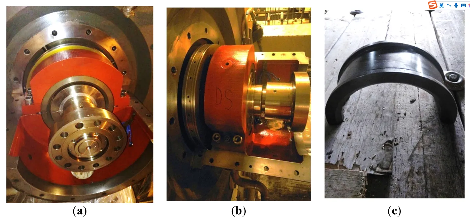
Following a comprehensive engineering report, which included detailed findings from the baroscopic inspection, it was determined that the primary cause of the vibration issues was the accumulation of fouling and scale deposits on the compressor cartridge. These deposits led to an imbalance within the compressor, resulting in high vibration levels that triggered shutdowns. The excessive vibrations caused significant wear and damage to the journal bearings, particularly affecting the bronze components ( and ). This wear and damage further aggravated the operational problems, increasing maintenance costs and extended downtime ( and ).
. (<b>a</b>) Centrifugal compressor bearing (front view); (<b>b</b>) Centrifugal compressor bearing (side view); (<b>c</b>) Journal bearing shell (taken at Oil&Gas operational Terminal from assigned task).
The report underscored the critical impact of fouling and scaling on the compressor’s performance and reliability. It emphasised the necessity of addressing these issues to prevent further damage and ensure efficient operation. The findings highlighted that the accumulation of fouling and scale deposits created an imbalance and contributed to the deterioration of essential components, thereby exacerbating the operational challenges. Consequently, regular maintenance and preventive measures to mitigate fouling and scaling were deemed crucial for maintaining the compressor’s optimal performance and reducing the frequency of high vibration trips.
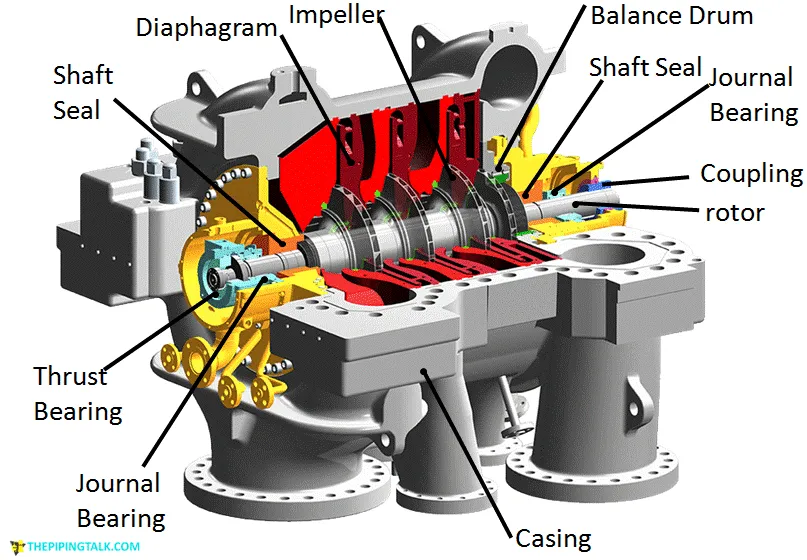
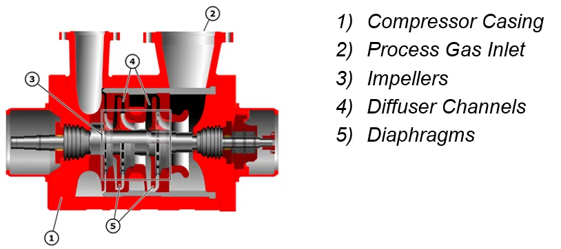
. Centrifugal compressors components Reference site Thepiping talk.
Additionally, the report identified that filling suction scrubbers with Monoethylene Glycol (MEG) leads to the creation of moisture. This moisture causes rust to form on the scrubbers and the piping system. During startup, all the deposits that have accumulated on the pipeline walls are dislodged and accumulated in the suction strainer. This accumulation causes the compressor to surge, leading to increased vibrations and subsequent damage to its internal components.
The investigation uncovered a recurring issue in the compressor system: frequent blockages in the first-stage suction strainer. These were caused by deposits formed from H
2S scaling and erosion of carbon steel pipelines. As these deposits built up, they triggered compressor surge events, disrupted gas flow, and damaged internal components—especially the journal bearings made of bronze.
These mechanical disruptions didn’t just affect performance; they led to increased vibration levels, which in turn caused further wear and tear. The result was a cycle of shutdowns, costly maintenance, and extended downtime. Engineers conducted baroscopic inspections and confirmed heavy fouling and scaling inside the compressor casing and pipelines, validating the severity of the issue.
A detailed engineering report linked the imbalance caused by these deposits directly to the vibration problems. It showed how the wear on bearings, particularly the bronze ones, accelerated due to the strain. Visual documentation ( and ) supported these findings, showing the physical damage to key components.
Another contributing factor was the use of Monoethylene Glycol (MEG) in suction scrubbers. While intended to help, MEG introduced moisture that caused rust. During startup, this rust and other deposits were flushed into the strainer, worsening the blockage and surge conditions.
Overall, the research highlighted how a combination of chemical reactions, material choices, and operational practices undermined the compressor’s reliability. It emphasised the need for better maintenance routines, smarter material selection, and more proactive monitoring to prevent these issues from escalating [
10,
11,
12,
13,
14,
15].
3. Results
The implementation of a structured maintenance and cleaning strategy yielded several key operational and mechanical improvements in the performance of the centrifugal compressor system.
3.1. Successful Chemical Cleaning of the First-Stage Cartridge
A specialised scale-melting agent was applied to the first-stage casing cartridge and retained for 48 h. Manual rotation of the shaft ensured even exposure of both sides of the cartridge. This method effectively dissolves wax and scale deposits, restores internal flow paths, and reduces mechanical resistance.
3.2. Effective High-Pressure Water Jet Cleaning
The compressor’s inlet and outlet nozzles and associated piping were cleaned using high-pressure water jets (5000–20,000 psi). This process successfully removed scale, sludge, and corrosion products, ensuring unobstructed flow and reducing the risk of localised pressure drops.
3.3. Improved Fouling Prevention via Diesel Injection
Monoethylene Glycol (MEG) injection was replaced with diesel in the suction scrubbers following the cleaning process. Diesel demonstrated superior solvency for wax and scale, effectively preventing future strainer blockages and maintaining suction flow integrity.
3.4. Progressive Solvent Efficiency
Three sequential fill-and-drain cycles were conducted during the chemical cleaning process. Each cycle showed a measurable reduction in the concentration of dissolved material, confirming the solvent’s effectiveness and the gradual removal of hydrocarbon-based fouling.
3.5. Operational and Economic Benefits
The chemical cleaning approach restored compressor performance and offered a substantial cost advantage. Compared to a full bundle replacement and overhaul (estimated at $1,000,000), the chemical cleaning process cost approximately $10,000, representing a 99% cost reduction. Additionally, downtime was minimised, further enhancing operational efficiency.
4. Discussion of Results
4.1. Operational Challenges and Fouling Mechanisms
The compressor system faced persistent operational challenges due to fouling caused by rust, wax, and scale deposits. These issues were exacerbated by moisture accumulation and corrosion within scrubbers and piping systems. Regular cleaning and inspection routines were essential to prevent rust formation and detect early signs of wear or damage. Lubrication of moving parts and the use of corrosion-resistant materials were also emphasised to reduce friction and extend component life.
Surge control systems played a critical role in maintaining operational stability. Continuous monitoring and tuning of control parameters helped mitigate the violent vibrations associated with surge events. Post-cleaning vibration analysis revealed a significant reduction in 1× vibration amplitudes, particularly in low-flow regions and the balance labyrinth, confirming the restoration of aerodynamic balance and mechanical stability.
Reduction in Vibration Levels: Post-cleaning vibration analysis revealed a significant decrease in 1× vibration amplitudes. This improvement is attributed to restoring aerodynamic balance and enhanced flow uniformity, particularly in the balance labyrinth and low-flow regions where fouling was most severe. The vibration reduction directly contributed to improved mechanical stability and a lower risk of unplanned shutdowns.
4.2. Evolution of Fouling Deposits
In 2020, the mineral composition of FGC1 was dominated by goethite (80%) and magnetite (20%), indicating a strong presence of iron oxides. By 2021, the composition had diversified significantly, with quartz becoming the most abundant mineral at 46%, followed by anorthite at 17%. Other minerals like calcite, goethite, magnetite, and hematite appeared in smaller proportions, suggesting a shift toward silicate and carbonate minerals. This change may reflect environmental or operational influences affecting the sample. By July 2022, the composition had transformed dramatically, with Sulphur making up 95% and marcasite 5%. This indicates a strong shift toward sulphide minerals, possibly due to chemical changes or contamination. The progression shows a clear transition from iron oxides to silicates and finally to sulphur-rich compounds. Such changes could be linked to different processing stages or exposure to varying conditions. Such conditions made compressor accumulation of deposits on the impeller and cause vibration and wear issues ().
. Historical strainer blockage samples.
The LP Separator is experiencing intermittent foaming and emulsification, which leads to heavier hydrocarbons (+C16) carrying over downstream equipment. The LP compressor inlet knock-out drum is undersized, allowing entrained liquid and foam to pass through, contributing to fouling and waxy deposit formation in the compressor flow path, including the balance labyrinth. Additionally, harder deposits—likely a mix of corrosion products and hydrocarbons—are forming in low-flow areas, exacerbating the issue. Over time, these deposits cause a gradual increase in 1× vibration levels, eventually triggering a high-high (HH) trip. The current mitigation strategy involves changing the compressor bundle, a routine action to address fouling.
Regular vibration analysis is important for detecting abnormal vibrations indicating potential issues. Using vibration sensors and monitoring equipment to gather data on the compressor’s performance allows for addressing abnormalities by investigating the root cause and taking corrective actions, such as balancing rotating components, tightening loose parts, or replacing worn-out bearings.
Using corrosion-resistant materials for components exposed to moisture and harsh environments, such as stainless steel and other alloys, can be more durable and less prone to rust. Improving the design of the compressor and associated systems to minimise areas where moisture can accumulate and cause rust, including better drainage systems and protective coatings, is also beneficial [
16,
17,
18,
19,
20,
21].
During the 2022 overhaul, fouling was identified in the LP compressor system, confirming earlier suspicions of performance degradation. The LP Separator had been intermittently experiencing foaming and emulsification, leading to the carry-over of heavier hydrocarbons (+C16) into downstream equipment. The undersized LP compressor inlet knock-out drum failed to effectively separate entrained liquids and foam, allowing them to enter the compressor. This resulted in the formation of waxy deposits along the compressor flow path, including the balance labyrinth. In low-flow areas, harder deposits formed, likely due to a combination of corrosion products and hydrocarbons. These deposits contributed to a gradual increase in 1× vibration levels, eventually reaching the high-high trip threshold. The standard response has been to change the compressor bundle to address the fouling. The 2022 findings validated the need for a more robust mitigation strategy to prevent recurrence ().
4.3. Chemical Cleaning Strategy and Effectiveness
Several hydrocarbon-based solvents were tested to address wax and scale fouling, including a commercial wax dissolver, toluene, diesel, and a specialised blend (EC6004A). Aromatic-rich formulations demonstrated superior performance in dissolving waxy deposits. A structured chemical cleaning method involving three sequential fill-and-drain cycles using a wax-dissolving solvent was developed. Each cycle showed a progressive reduction in dissolved material, confirming the cleaning process’s effectiveness ().
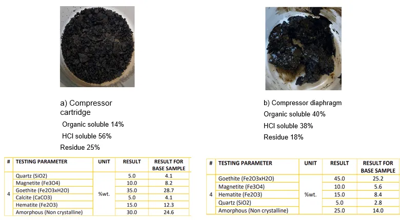
. (<b>a</b>). Compressor Cartridge deposition; (<b>b</b>) compressor diaphragm deposition.
The double dry gas seal system was maintained under continuous pressure to prevent solvent ingress and protect seal integrity during cleaning. Real-time monitoring systems tracked temperature, pressure, and vibration, enabling predictive maintenance and early fault detection [
22,
23,
24].
Post-cleaning vibration data showed a marked decrease in amplitudes, particularly at 1× running speed. This confirmed the successful removal of flow restrictions and restoration of mechanical balance.
A chemical cleaning method statement was systematically developed to facilitate the removal of wax-based deposits from the compressor internals. The double dry gas seal system was maintained under continuous pressure to ensure the integrity and operational reliability of critical components during the cleaning process. This precautionary measure effectively isolated the seal from potential exposure to cleaning solvents, thereby mitigating the risk of contamination or mechanical degradation.
Continuous monitoring systems track the performance of the compressor in real-time, including sensors for temperature, pressure, vibration, and other critical parameters. Analysing the data collected from monitoring systems helps identify trends and potential issues before they become serious problems, using predictive maintenance techniques to schedule maintenance activities based on the actual condition of the equipment.
Three sequential fill-and-drain cycles were conducted using the wax-dissolving (WD) solvent as part of the chemical cleaning procedure. Each cycle involved filling the system with a solvent, allowing sufficient contact time for dissolution of wax deposits, followed by draining and analysis of the recovered fluid. Observations indicated a progressive reduction in the concentration of dissolved material in the drained solvent across the cycles. This trend suggests a decreasing load of removable wax content, confirming the gradual effectiveness of the cleaning process and the solvent’s capacity to mobilise and extract hydrocarbon-based fouling ().
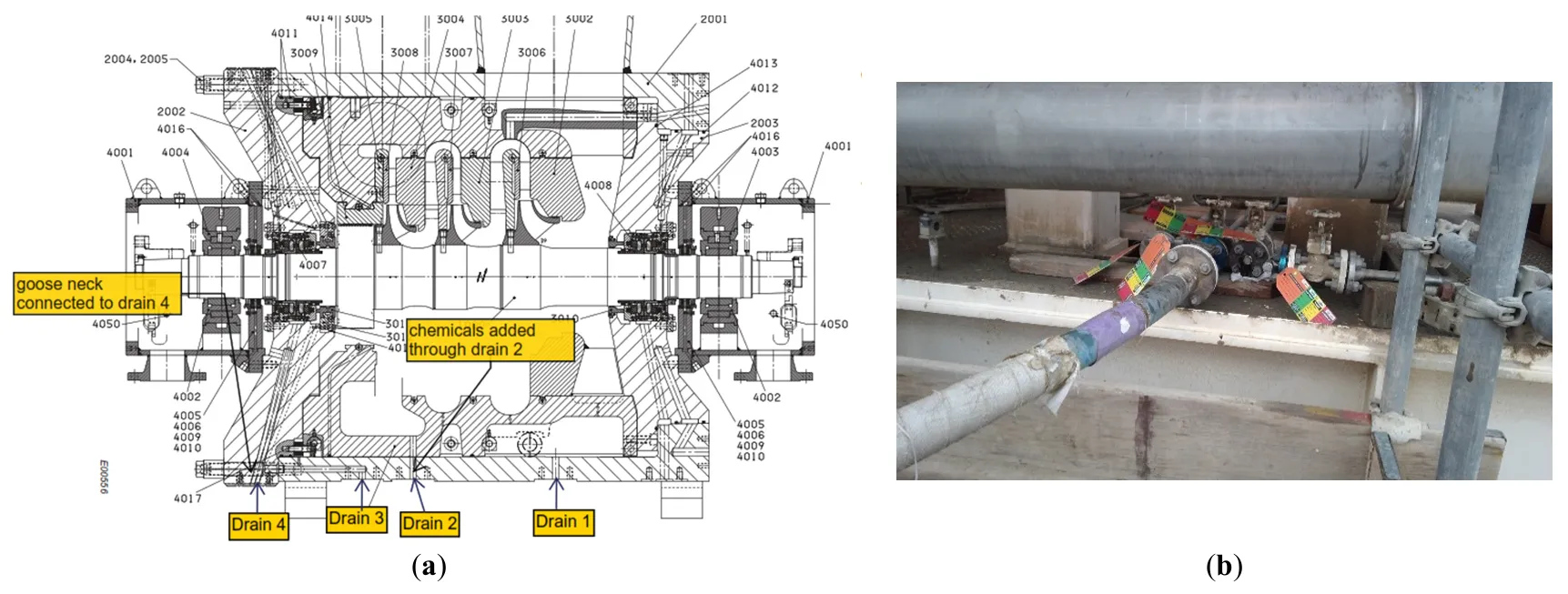
. (<b>a</b>). Compressor chemical injection and drain points (<b>b</b>). Connection at site.
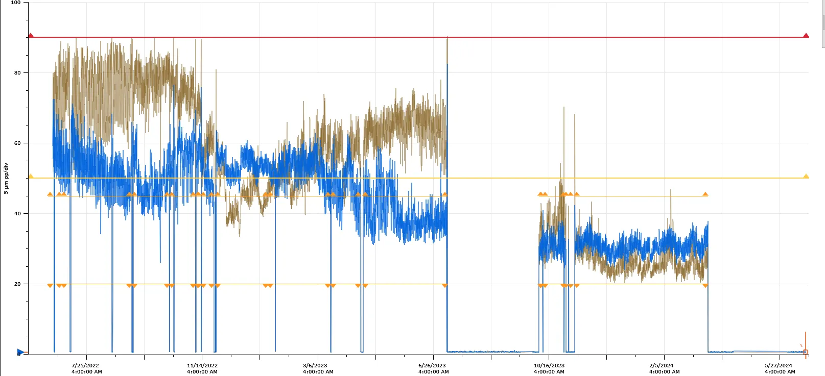
The chemical cleaning process, involving three cycles of wax-dissolving solvent, had a measurable impact on overall compressor vibration levels. Prior to cleaning, vibration amplitudes, particularly at 1× running speed, had been observed to increase progressively, eventually approaching or exceeding high-high (HH) trip thresholds. Following the cleaning intervention, a noticeable reduction in vibration levels was recorded, indicating successful removal of wax and deposit-induced flow restrictions ().
. Impact to overall Vibration (Before cleaning) and After chemical cleaning. Blue line-amplitude for LP compressor, DE-Y axis, Brown line-amplitude for LP compressor, DE-Y axis.
Chemical cleaning proved to be a cost-effective alternative to full bundle replacement. With an estimated cost of $10,000 compared to $1,000,000 for overhaul, it offered a 99% cost reduction. Additionally, it minimised downtime and operational disruption, making it a highly attractive maintenance strategy.
Given the variability in gas composition from oil wells, maintaining compressor parameters strictly within design specifications is challenging. A zero-defect solution is not feasible under such dynamic conditions. However, continuous improvement and proactive maintenance can ensure high-quality service and equipment reliability.
A zero-defect maintenance strategy was adopted to eliminate recurrence of vibration and wear issues due to strainer obstruction. This included:
Root Cause Elimination: Standardised chemical cleaning protocols ensured complete removal of wax and scale.
MEG Replacement: Diesel injection into suction scrubbers replaced MEG, offering better solvency and preventing deposit formation.
Precision Monitoring: Upgraded sensors and predictive analytics enabled early detection and intervention.
Design and Material Enhancements: Optimised strainer mesh sizes and corrosion-resistant materials reduced blockage risk.
Standardised Protocols and Training: Maintenance procedures were codified and supported by technician training to ensure consistent execution.
Together, these measures form a robust framework for sustaining compressor performance, reducing vibration-induced failures, and extending equipment lifespan—fully supporting the conclusions drawn from this study [
25].
5. Conclusions
- 1.
-
Multiple maintenance strategies were evaluated for managing fouling and ensuring optimal performance of centrifugal compressors.
- 2.
-
Chemical Cleaning: Chemical cleaning demonstrated significant operational and economic benefits, especially in addressing wax and scale deposition within compressor internals.
- 3.
-
Cleaning Process: The method involved three cycles of wax-scale dissolving solvent, with each cycle showing a reduction in dissolved material, indicating progressive cleaning efficiency.
- 4.
-
The double dry gas seal was maintained under continuous pressurisation throughout the process to safeguard seal integrity and prevent chemical fluid ingress to sealing system and damage.
- 5.
-
A measurable reduction in overall vibration levels was observed post-cleaning, confirming the restoration of flow dynamics and mechanical balance.
- 6.
-
Economically, chemical cleaning proved highly advantageous, with an estimated cost of $10,000 compared to approximately $1,000,000 for a full bundle change and overhaul.
- 7.
-
Three additional maintenance methods were also assessed:
-
-
High-pressure water jet cleaning: Effective for physical debris in nozzles.
-
-
Chemical cleaning of casing cartridges: Ideal for scale removal.
-
-
Diesel injection into scrubbers: Suitable for dissolving wax and scale.
- 8.
-
The selection of an appropriate method should be guided by deposit characteristics, safety considerations, and cost-effectiveness, in alignment with industry standards such as API 617.
- 9.
-
Together, these strategies provide a comprehensive toolkit for maintaining compressor reliability and performance in hydrocarbon processing environments.
Author Contributions
Conceptualization, T.E.F.; Methodology, T.E.F. and J.N.A. Software, T.E.F.; Validation, T.E.F., J.N.A.; Formal Analysis, T.E.F.; Resources, T.E.F.; Data Curation, T.E.F., J.N.A.; Writing—Original Draft Preparation, T.E.F.; Writing—Review & Editing, T.E.F., J.N.A.; Visualization, T.E.F.; Supervision, J.N.A.; Project Administration, J.N.A.; Funding Acquisition, No any funding.
Ethics Statement
Not applicable.
Informed Consent Statement
Not applicable.
Data Availability Statement
All data generated or analyzed during this study are available from the corresponding author upon reasonable request.
Funding
This research received no external funding.
Declaration of Competing Interest
The authors declare that they have no known competing financial interests or personal relationships that could have appeared to influence the work reported in this paper.
Generative AI Statement
Statement of the Use of Generative AI and AI-assisted technologies in the Writing Process. During the preparation of this manuscript, the author(s) used Copilot in order to paraphrasing sentences. After using this tool/service, the author(s) reviewed and edited the content as needed and take(s) full responsibility for the content of the article.
References
-
1.
API Standard 617; Axial and Centrifugal Compressors and Expander-Compressors for Petroleum, Chemical and Gas Industry Services. American Petroleum Institute: Washington, DC, USA, 2002.
-
2.
Ali H, Nguyen T. Computational fluid dynamics analysis of flow through blocked suction strainers in compressors.
Int. J. Fluid Mach. 2020,
29, 15–22.
[Google Scholar]
-
3.
Aslanov JN, Mammadov GIA, Mamedov VT. Stress-strain state of sealing rubber membranes at large deformations.
J. Appl. Mech. Tech. Phys. 2020,
61, 152–157.
[Google Scholar]
-
4.
Aslanov JN, Sultanova AB, Huseynli ZS, Mustafayev FF. Determination of radial strains in sealing elements with rubber matrix based on fuzzy sets.
J. Appl. Mech. Tech. Phys. 2021,
61, 152–157.
[Google Scholar]
-
5.
Baddam P. Cracked gas Compressor Fouling and Anti-Fouling Technologies; Turbomachinery International: Iselin, NJ, USA, 2018.
-
6.
Bernocchi A, Fontana M. Rotor Vibrations Induced in a Pipeline Centrifugal Compressor by Inlet Gas Flow Excitation; Turbomachinery Laboratory, Texas A&M: College Station, TX, USA, 2024.
-
7.
Brown K, Davis L. Case study: Suction strainer blockage leading to compressor failure.
Eng. Fail. Anal. 2017,
76, 98–105.
[Google Scholar]
-
8.
Chen L, Zhang Y. Impact of particulate contamination on compressor suction strainers and performance degradation.
Appl. Mech. Mater. 2021,
876, 45–52.
[Google Scholar]
-
9.
Chikwe AO, Okereke NU, Ndubueze MO, Duruonyeaku AN. Modeling of wax deposition in crude oil pipeline using simulation.
Am. J. Eng. Res. 2021,
10, 117–125.
[Google Scholar]
-
10.
Meher-Homji CB, Bromley A. Gas turbine performance deterioration and compressor washing. In METS Symposium Proceedings; Turbomachinery Laboratory, Texas A&M Engineering Experiment Station: College Station, TX, USA, 2013; pp. 1–12.
-
11.
Noor A, Eckert J. Pulsation-induced vibration in pipeline compressors: A root cause analysis.
J. Vib. Eng. 2018,
34, 98–107.
[Google Scholar]
-
12.
O’Connor M, Zhao H. Maintenance scheduling for suction strainers in high-pressure compressors.
Reliab. Eng. Syst. Saf. 2018,
172, 45–52.
[Google Scholar]
-
13.
Onwumelu DC, Onwuka MK, Nnebeana SE, Okoro TC, Ekeocha AF, Offurum CC, et al. Crude oil and the problem of wax deposition on pipeline systems during transportation: A review.
World J. Adv. Res. Rev. 2022,
15, 781–798.
[Google Scholar]
-
14.
Patel S, Mehta R. Economic evaluation of compressor cleaning strategies.
J. Ind. Econ. Maint. 2021,
18, 55–62.
[Google Scholar]
-
15.
Singh A, Mehta R. Design optimization of suction strainers to minimize blockage in compressors.
J. Mech. Des. Optim. 2019,
14, 67–74.
[Google Scholar]
-
16.
Coutinho S, Silva R. Flow assurance in deepwater oil production: Wax deposition challenges.
J. Pet. Technol. 2006,
58, 45–52.
[Google Scholar]
-
17.
Fernandez R, Kim S. Innovative filtration materials for suction strainers in centrifugal compressors.
J. Adv. Mater. Res. 2020,
1024, 88–95. doi:10.4028/www.scientific.net/AMR.1024.88.
[Google Scholar]
-
18.
Galta T. Wax deposition in subsea pipelines: Mechanisms and mitigation.
Offshore Eng. J. 2014,
22, 77–84.
[Google Scholar]
-
19.
Garcia P, Thompson D. Preventive maintenance techniques for avoiding suction strainer blockage in petrochemical compressors.
J. Process Eng. 2018,
33, 210–218.
[Google Scholar]
-
20.
Garcia-Hernandez J, Lopez M. Surge and flow instability in fouled compressors: A diagnostic approach.
J. Process Dyn. 2015,
27, 215–223.
[Google Scholar]
-
21.
Hemati A, Ghasemi M. Predictive modeling of journal bearing failure using hybrid machine learning techniques.
J. Fail. Anal. Prev. 2025,
25, 34–42.
[Google Scholar]
-
22.
Kiyingi J, Ochieng R. Diesel-based cleaning methods for wax and hydrocarbon fouling in gas compressors.
Pet. Eng. Rev. 2022,
16, 88–96.
[Google Scholar]
-
23.
Kumar R, Patel S. Mitigation strategies for suction strainer blockage in industrial compressors.
Int. J. Ind. Maint. 2019,
12, 89–95.
[Google Scholar]
-
24.
Mamedov VT, Sultanova AB. Operational deviations and their role in compressor fouling.
J. Mech. Syst. 2023,
17, 101–110.
[Google Scholar]
-
25.
Hosseini M. Real-time condition monitoring in rotating machinery: A predictive maintenance approach.
Int. J. Ind. Syst. 2024,
19, 55–68.
[Google Scholar]