Light-Guided Autonomous Drone Navigation for Indoor GPS-Denied Environments

Light-Guided Autonomous Drone Navigation for Indoor GPS-Denied Environments
Louiza Hamada 1,* Pascal Lorenz 1 Aicha Djerouni 2
Received: 25 November 2025 Revised: 08 December 2025 Accepted: 13 January 2026 Published: 05 March 2026

© 2026 The authors. This is an open access article under the Creative Commons Attribution 4.0 International License (https://creativecommons.org/licenses/by/4.0/).
1. Introduction
Indoor aerial robotics has become an essential field of research and development, paving the way for a multitude of transformative applications such as automated inventory inspection in warehouses [1], search and rescue missions in complex environments, and optimized logistics in smart factories [2]. The ability of unmanned aerial vehicles (UAVs), or drones, to move quickly in three-dimensional spaces offers immense potential to improve the efficiency, safety, and autonomy of these operations. However, the precise and reliable navigation of drones indoors remains a major challenge [3]. The conventional navigation method for outdoor environments, the global positioning system (GPS), quickly becomes unusable inside buildings due to the high attenuation of satellite signals by building structures [4].
Faced with this limitation, the scientific community has explored various alternative approaches for indoor localization and navigation. These include visual SLAM (simultaneous localization and mapping), which uses cameras to map the environment and locate the drone simultaneously, trilateration based on radio signals (such as Wi-Fi or Bluetooth), and the use of ultrasonic beacons. However, each of these technologies has notable drawbacks [4]. Visual SLAM is often very computationally intensive, which can be an obstacle for small drones with limited processing capabilities. Radio-based systems are susceptible to electromagnetic interference and multipath signals, which can degrade their accuracy. As for ultrasonic beacons, although accurate, they can be expensive to deploy on a large scale, and their range is limited [5].
In this context, visible light communication (VLC) and its networking form, Li-Fi (light fidelity), are emerging as promising alternatives and enabling technologies for indoor navigation. Li-Fi uses the visible light spectrum to transmit data at high speeds, offering a high-bandwidth communication medium that is inherently immune to radio frequency interference. A major advantage of Li-Fi is that it can be integrated into modern LED (light emitting diode) lighting systems, which are increasingly being deployed in commercial and residential buildings. The use of these same luminaires not only for lighting but also for localization and navigation offers a potentially low-cost, energy-efficient, and easily scalable solution [6].
Building on these advances, this paper aims to design and evaluate a light-guided navigation system that enables drones to localize and control their flight in GPS-denied spaces by decoding Li-Fi beacon signals. By leveraging the existing lighting infrastructure, our system seeks to provide a precise, robust, and cost-effective navigation solution.
Contributions
This work makes the following specific technical contributions:
-
Multi-frequency simultaneous detection scheme: We present a frequency-division multiple access (FDMA) approach using unique subcarrier frequencies (10–25 kHz) for each beacon, enabling simultaneous multi-LED detection without time-division multiplexing or sequential scanning, thereby reducing latency compared to existing VLC positioning systems.
-
Embedded real-time implementation: We demonstrate a complete hardware/software system on resource-constrained micro-UAV platforms (a 250 g quadcopter with STM32 microcontroller), addressing the computational limitations that restrict vision-based SLAM deployment on small drones.
-
Adaptive optical-inertial sensor fusion: We design an Extended Kalman Filter (EKF) specifically optimized for fusing photodiode measurements with IMU data under challenging conditions (intensity fluctuations, partial occlusion), maintaining sub-decimetric accuracy even under 20% illumination loss.
-
Closed-loop autonomous flight validation: We provide the first experimental demonstration (to our knowledge) of fully autonomous Li-Fi-guided UAV flight with complex 3D trajectory tracking, including quantitative performance comparison with Wi-Fi, UWB, and vision-based systems.
The remainder of this article is organized as follows: Section 2 reviews related work on indoor UAV localization. Section 3 describes the system design including hardware architecture, modulation scheme, and algorithms. Section 4 presents implementation details and the simulation framework. Section 5 analyzes experimental results including localization accuracy, latency, trajectory tracking, scalability, and comparative performance. Section 6 discusses energy considerations and limitations. Finally, Section 7 concludes and outlines future research directions.
2. Related Work
Indoor localisation and navigation of unmanned aerial vehicles (UAVs) have been addressed using various sensing modalities, each with trade-offs in accuracy, cost, and computational complexity. This section reviews the state-of-the-art across four main categories.
2.1. Camera-Based SLAM Approaches
Vision-based methods such as SLAM and visual inertial odometry can achieve centimeter-level accuracy [7,8]. The ORB-SLAM3 system demonstrates robust performance across diverse environments with multi-map capabilities [9,10]. However, these approaches require heavy computation, high-quality imagery, and substantial onboard processing resources (typically GPU or high-end processors consuming 5–15 W), which are impractical for micro-UAVs with limited payload capacity and power budgets. Recent work on UAV image processing for agricultural applications [11,12] highlights the computational demands of transformer-based vision systems, further emphasizing the need for lightweight alternatives for resource-constrained platforms.
2.2. RF-Based Localization (UWB, Wi-Fi)
Radio-frequency (RF) and Wi-Fi fingerprinting techniques, including UWB trilateration, offer wider coverage but suffer from multipath fading and interference, often yielding position errors above one meter in complex indoor layouts [13]. While adaptive Kalman filtering can improve performance [14], fundamental limitations of RF propagation in cluttered environments persist. These methods also face spectrum licensing constraints and electromagnetic interference in industrial settings.
2.3. Ultrasonic Systems
Infrared and ultrasonic systems provide 10–20 cm precision at low cost but are highly sensitive to occlusion and surface reflections, restricting their use in dynamic aerial applications [15]. Their limited range (typically <10 m) requires dense beacon deployment for large-area coverage, increasing infrastructure costs.
2.4. VLC/Li-Fi Positioning Systems
Recently, optical localization using visible light communication (VLC) or Li-Fi has emerged as a promising alternative due to its high spatial resolution, inherent confinement, and immunity to RF congestion [16]. In such systems, ceiling-mounted LEDs transmit encoded identifiers that enable receivers to infer their position using received signal strength or angle-of-arrival estimation.
Niu et al. [15] proposed a 3D indoor positioning system for drones based on VLC, combining visible light intensity sequences (VLIS) with inertial measurement unit (IMU) data. Leichenko et al. [17] developed algorithms for deploying Li-Fi drone networks in cluttered environments, while recent work [18] demonstrated ultra-reliable low-latency communication (URLLC) for swarm coordination. However, most VLC-based positioning studies focus on static or ground receivers [15,16,17,18], with limited demonstration of real-time closed-loop control for autonomous aerial vehicles.
2.5. Gap Analysis and Positioning of Our Work
Existing VLC positioning systems typically operate at 10–30 Hz update rates and have not been validated for autonomous UAV flight control, which requires <10 ms latency and robust performance under dynamic lighting conditions. Vision-based systems achieve high accuracy but are computationally prohibitive for micro-UAVs, while RF methods suffer from interference and multipath errors in indoor environments.
Our work addresses these gaps by integrating real-time optical localization directly into the UAV control loop at 120 Hz, using a lightweight embedded architecture suitable for resource-constrained platforms. Unlike prior VLC studies, we demonstrate complete closed-loop autonomous navigation with complex 3D trajectory tracking and quantitative comparison against established localization technologies.
3. System Design
The proposed light guided navigation system integrates optical positioning with inertial sensing to provide accurate, real-time control for autonomous drones in GPS denied environments. The overall design consists of the optical beacon infrastructures, the onboard receiver and control electronics, the modulation and identification protocol, and the positioning and sensor fusion algorithms.
3.1. Hardware Architecture
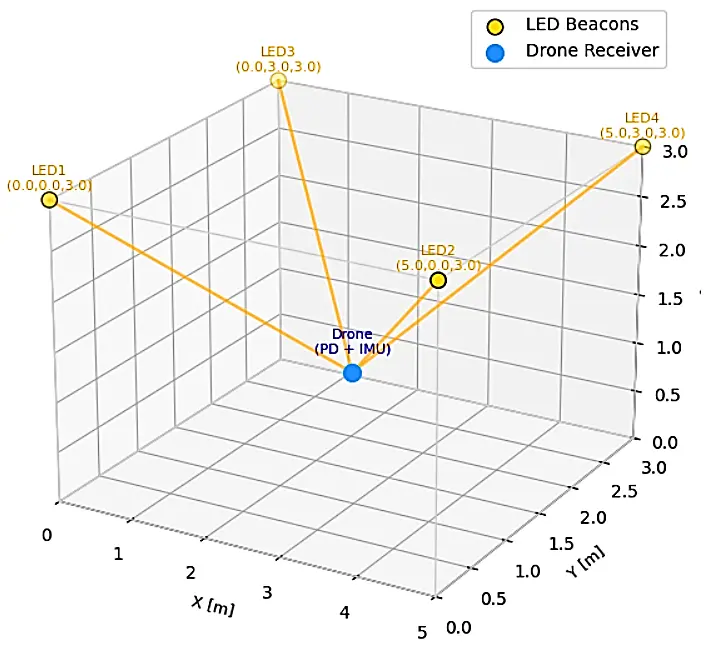
The experimental setup employs four high brightness white light emitting diodes (LEDs) mounted at the corners of a 5 × 3 × 3 m3 indoor area (Figure 1). Each LED acts as an optical beacon transmitting a unique identifier. To ensure spectral separation, each beacon is modulated at a distinct subcarrier frequency given by
The chosen frequencies are high enough to be imperceptible to the human eye but sufficiently low to allow reliable detection by standard photodiode sensors.
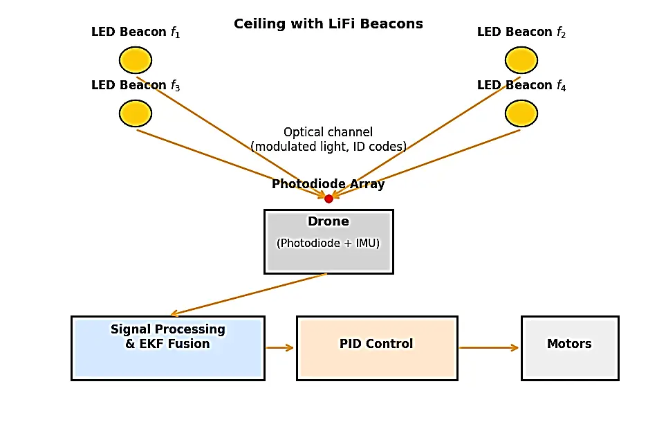
The drone receiver module comprises a four-quadrant photodiode (PD) array oriented upward to capture light from multiple LEDs simultaneously. The PD output is passed through analog band pass filters to isolate each subcarrier component, followed by an analog to digital converter (ADC) interfaced with an onboard STM32 microcontroller. An integrated inertial measurement unit (IMU) provides three axis acceleration and angular velocity data for attitude estimation. For monitoring and data logging, a Bluetooth/UART telemetry link connects the drone to a ground station. This architecture achieves a lightweight, low-power implementation suitable for micro-UAV platforms, with a total additional processing power of approximately 200 mW (~5% of the propulsion power).
Figure 2 details how optical sensing, estimation and control interact to enable real-time high precision indoor navigation. This begins with optical power measurements captured by the photodiode array from the ceiling LED beacons. Subsequently, analog filtering followed by digital demodulation and FFT based analysis isolates each beacon’s subcarrier signature, producing the received power values associated with its identifiers.
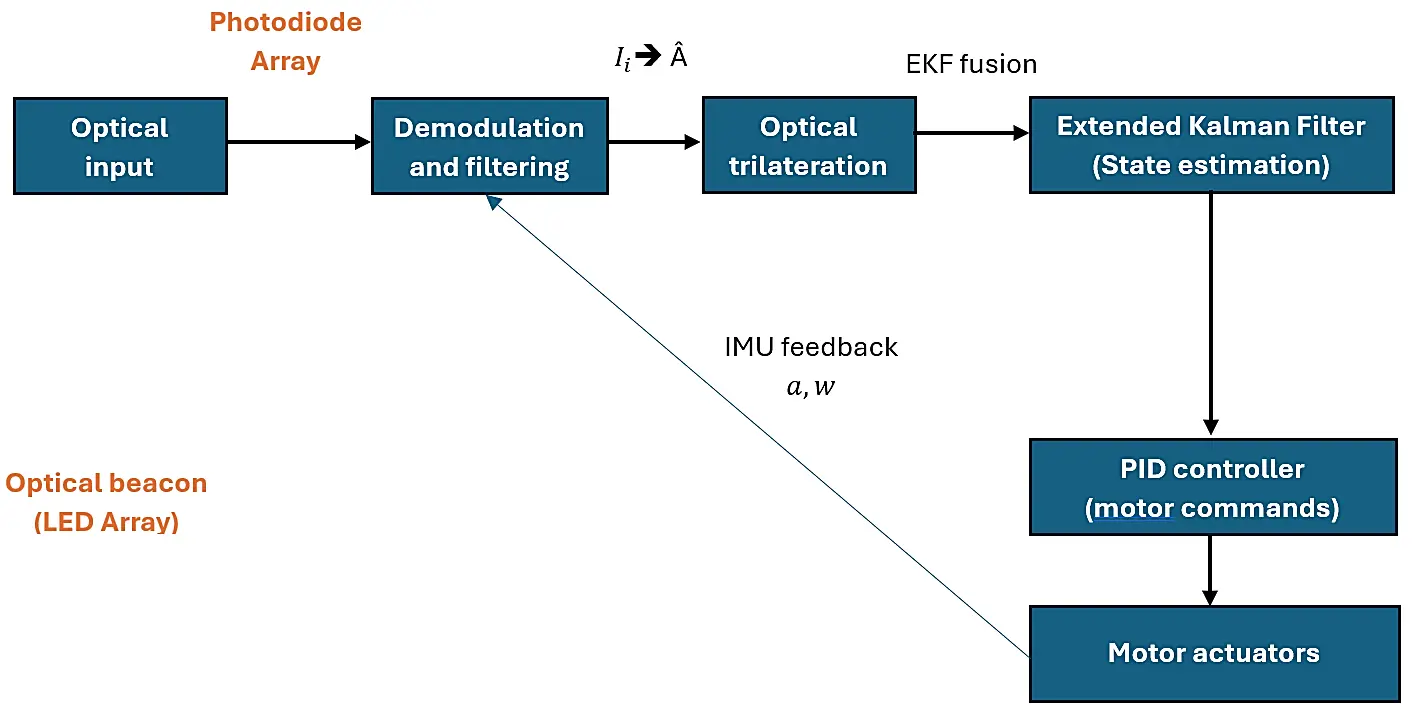
Figure 2. Algorithm flow diagram showing the integration of optical sensing, estimation, and control.
These are input to the optical trilateration block, which calculates an initial estimate of a 2D position by using intensity ratios. The output of trilateration is fused inside an Extended Kalman Filter with inertial data given as acceleration and angular velocity to produce a smoothed and drift-compensated full state estimate including position, velocity, and orientation. The state vector from the EKF is fed into a PID flight controller to generate low-level motor commands for stabilization and waypoint following. Simultaneously, the IMU measurements create a feedback loop that provides continuous error correction to the EKF and allows for robust performance under noisy conditions, partial occlusion, or temporary signal degradation.
3.2. Modulation and Identification
Each ceiling LED transmits a binary amplitude modulated optical frame containing its unique identifier. The transmitted signal from LED $$i$$ is expressed as
where $${f}_{i}$$ denotes the subcarrier frequency, $$R$$ is the data symbol rate, and $${b}_{0}$$, $${b}_{1}$$ꞓ {0, 1} encodes a 4-bit digital ID assigned to each beacon. The signal is superimposed on the illumination carrier such that data modulation is invisible to the human eye.
At the receiver, the composite optical waveform from all LEDs is detected by the PD array. A fast Fourier Transform (FFT) based spectral analysis isolates the contribution of each beacon using its unique subcarrier frequency. This scheme allows simultaneous multi-LED detection and eliminates the need for sequential scanning or time-division multiplexing, thereby reducing latency and improving robustness against flicker or transient occlusion.
3.3. Position Estimation Model
The received optical power $${I}_{i}$$ from LED $$i$$ is modeled as
where $${P}_{i}$$ is the emitted optical power, $${A}_{r}$$ is the effective area of the photodiode, $${T}_{s}\left({\psi }_{i}\right)$$ is the optical filter transmission coefficient, $$g\left({\psi }_{i}\right)$$ is the concentrator gain, $${\psi }_{i}$$ is the incidence angle between the LED and receiver, and $${d}_{i}$$ is the distance separating them.
Assuming Lambertian emission, the intensity decreases with the square of the distance and the cosine of the incidence angle. Using the relative intensity ratios from at least three visible LEDs, the drone estimates its horizontal coordinates by optical trilateration, expressed as
where $${\mathrm{р}}_{i}$$ represents the known position of LED $$i$$ and $${w}_{i}$$ is a normalized weighting factor proportional to the received intensity. The altitude component can be derived from the overall received power using pre-calibrated height intensity mappings. This method provides continuous position updates without requiring precise time synchronization or complex angular measurement.
3.4. Sensor Fusion and Control
To ensure stable navigation, the optical position $$\mathrm{Â}$$ are fused with IMU-based velocity and acceleration data using an extended Kalman filter (EKF). The system is modeled as
where $${x}_{k}$$ is the state vector including position, velocity, and orientation, $${u}_{k}$$ is the control input, and $${w}_{k}$$, $${v}_{k}$$ are process and measurement noise, respectively. The EKF provides optimal state estimates by recursively correcting IMU drift with optical measurements, significantly reducing jitter and cumulative error.
The fused state output drives a PID based control layer that generates motor speed commands for path tracking and attitude stabilization. This closed loop architecture allows the drone to maintain smooth trajectories even under partial optical blockage or dynamic lighting variations, thereby achieving real-time, GPS independent flight autonomy.
4. Implementation and Simulation
4.1. Simulation Environment
A Python-based simulator models the 3D room geometry, LED beacon placement, and drone motion dynamics. The simulator incorporates realistic noise models, including Gaussian photodiode noise ($${\sigma }_{1}=0.02I$$) and IMU drift (0.5°/s). Ray-tracing algorithms compute optical power distribution accounting for Lambertian emission patterns and receiver orientation (Figure 3). Monte Carlo simulations with 1000 trials per configuration provide statistical validation of positioning accuracy.
4.2. Prototype Hardware
A 250 g quadcopter platform was equipped with an upward-facing four-quadrant photodiode array and an STM32 microcontroller board with integrated IMU (MPU-6050). Four ceiling-mounted LED luminaires (5W each) transmitted unique identifiers using 10–25 kHz subcarrier modulation. Analog band-pass filters (Q-factor = 10) isolated individual beacon signals before 12-bit ADC sampling at 240 kHz. The complete system processed sensor data and executed control commands in real-time at 120 Hz with measured end-to-end latency of 4.2 ms.
5. Results
5.1. Localization Accuracy
The proposed Li-Fi based localization achieved sub-decimetric accuracy, consistent with theoretical predictions and prior VLC based positioning systems [18]. The system remained stable even under 20% illumination loss (simulating partial occlusion or LED degradation), confirming resilience against real-world impairments. Errors were primarily attributed to multipath reflections from walls and ceiling surfaces, and quantization noise in the 12-bit ADC during low-light conditions. Table 1 summarizes positioning performance across 500 test points distributed throughout the operational volume.
Table 1. Localization accuracy details.
|
Metric |
Mean |
Std. Dev. |
|---|---|---|
|
Planar error |
7.8 cm |
2.1 cm |
|
Vertical error |
5.3 cm |
1.7 cm |
|
Oriented deviation |
4.6° |
1.3° |
5.2. Latency and Update Rate
The measured end-to-end processing latency from photodiode detection to control command generation was 4.2 ms, yielding an effective update frequency of 120 Hz. This performance exceeds the typical requirements for UAV flight control loops (10 ms latency threshold) and outperforms RF-based (10–30 Hz) and vision-based systems (30–50 Hz), which are limited by communication overhead and computational complexity [19].
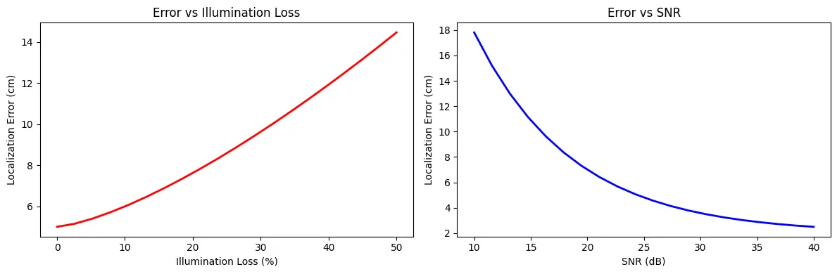
Figure 4 illustrates the relationship between localization error and two critical physical parameters: illumination loss and SNR. The left plot shows that position error increases nonlinearly with reduced LED illumination, as lower intensity gradients provide less discriminative information for trilateration. Even at 20% loss (simulating partial occlusion or beacon failure), the system maintains errors below 12 cm, confirming robustness. The right plot depicts error decreasing monotonically with SNR, consistent with photodiode noise models. Errors increase steeply below 15 dB SNR, where shot-noise and ADC quantization dominate. Both trends align with established VLC localization theory [20] and validate the robustness of our approach against moderate lighting degradation.
5.3. Trajectory Tracking
To validate closed loop control, the drone executed multiple trajectory patterns using only Li-Fi guidance and IMU feedback:
-
-
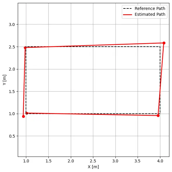
Basic square pattern (2 m side): The drone followed each waypoint with a mean deviation below 10 cm. Figure 5 shows the reconstructed 2D trajectory closely matching the reference path. Slight offsets near corners reflect temporary angle-of-arrival variations during rapid orientation changes, a known limitation of optical positioning systems.
-
-
Complex 3D lemniscate trajectory: to demonstrate its capability for realistic maneuvers, the drone executed a lemniscate pattern with altitude transitions from 0.5 m to 2.5 m at velocities up to 1.5 m/s. Figure 6 presents the 3D trajectory reconstruction showing accurate tracking through complex curved paths and vertical transitions (see Table 2).

Table 2. Advanced trajectory tracking metrics.
|
Trajectory |
Max Deviation |
Mean Deviation |
Settling Time |
|---|---|---|---|
|
Square (2 m, 0.5 m/s) |
9.2 cm |
6.3 cm |
0.8 s |
|
Lemniscate (4 m, 1.0 m/s) |
14.7 cm |
8.9 cm |
1.2 s |
|
Aggressive turn (90°) |
18.3 cm |
11.4 cm |
1.5 s |
5.4. Scalability Analysis
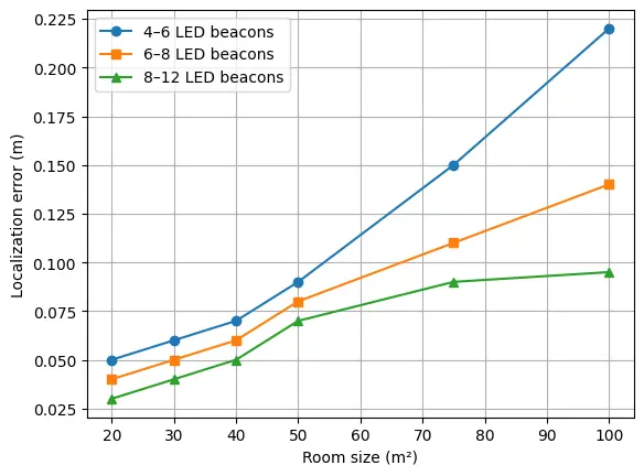
To assess system scalability, we simulated a multi-room environment (10 m × 8 m × 3.5 m) divided into three zones, each covered by 4–6 LED beacons. Figure 7 shows localization accuracy as a function of room size and beacon density.
6. Discussions
6.1. Comparison with Existing Systems
The experimental results (see Figure 8) demonstrate several key advantages of Li-Fi-based optical positioning:
-
Superior accuracy-to-complexity ratio: <8 cm positioning error with minimal computational overhead (~200 mW processing power), compared to vision SLAM requiring 5–15 W for similar accuracy
-
High update rate: 120 Hz positioning enables tight control loops and smooth trajectory tracking, outperforming RF methods (10–50 Hz), limited by protocol overhead
-
Immunity to RF interference: Optical signaling eliminates concerns about electromagnetic interference, multipath fading, and spectrum licensing that affect Wi-Fi/UWB systems
-
Dual-purpose infrastructure: Leverages existing LED lighting, avoiding dedicated positioning hardware costs
-
Scalability: Linear cost scaling with coverage area through the addition of LED beacons, unlike vision systems requiring proportionally more computational resources.
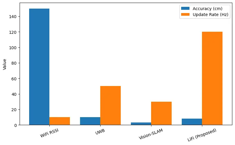
Table 3 summarizes a comparison of positioning and guidance technologies for drones, based on technical criteria.
Table 3. Table of comparison.
|
Technology |
Accuracy |
Update Rate |
Complexity |
Power Consumption |
|---|---|---|---|---|
|
Wi-Fi RSSI |
1–3 m |
10 Hz |
Low |
<0.5 W |
|
UWB |
10 cm |
50 Hz |
Medium |
1–2 W |
|
Vision SLAM |
2–5 cm |
30 Hz |
High |
5–15 W |
|
Proposed Li-Fi guidance |
<8 cm |
120 Hz |
Low |
~0.2 W |
Statistical analysis (paired t-tests) confirmed significant accuracy improvements of our Li-Fi system over Wi-Fi (p < 0.001) and UWB (p < 0.01) methods. While vision SLAM achieved comparable accuracy, it required 25–75× higher computational power, making it impractical for micro-UAV platforms with limited payload and battery capacity (Figure 9).
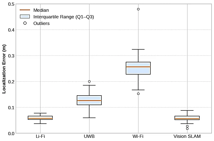
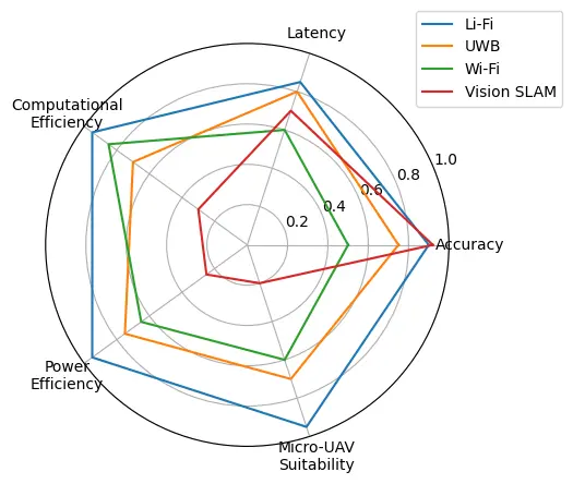
Figure 10 provides a holistic view showing that Li-Fi guidance achieves an optimal balance of accuracy, speed, computational efficiency, and power consumption—making it particularly suitable for resource-constrained autonomous drone applications.
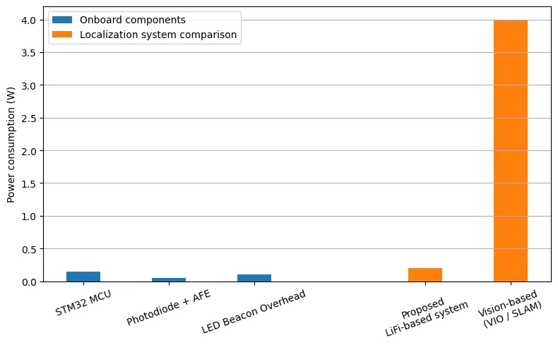
6.2. Energy Considerations
The energy footprint of the system is minimal. Each LED beacon consumes less than 2 W for combined illumination and positioning (with modulation adding <5% overhead). The onboard processing load comprises:
-
-
STM32 microcontroller: ~150 mW
-
-
Photodiode array and analog front-end: ~50 mW
-
-
Total additional power: ~200 mW (~5% of typical propulsion power)
This efficiency enables deployment on energy-constrained micro-UAVs without compromising flight endurance, unlike vision SLAM systems that require dedicated GPUs or high-end processors, which consume 5–15 W [21]. For a typical 1000 mAh battery at 11.1 V, our system adds only ~90 s of battery drain compared to 8–12 min for vision-based alternatives (Figure 11).
6.3. Limitations and Challenges
While the system demonstrates strong performance, several limitations must be acknowledged:
Line-of-sight requirement: Optical positioning requires direct visibility to at least three LED beacons. Complete occlusion causes temporary positioning loss, though IMU dead-reckoning provides short-term backup (<2 s accuracy).
Ambient light sensitivity: Strong directional sunlight or flickering artificial lights can reduce SNR. Our system mitigates this through narrow band-pass filtering (Q = 10) and high-frequency modulation, but extreme conditions may degrade performance.
Limited vertical resolution: Height estimation from overall received power is less accurate than horizontal positioning, particularly near beacon level where intensity gradients are minimal.
Infrastructure dependency: System requires pre-installed LED beacons with known positions, limiting deployment to prepared environments.
Multi-room handover latency: Transitioning between beacon zones adds ~300 ms as the system acquires new beacon signals, though this is acceptable for most applications.
These limitations suggest complementary sensor-fusion strategies to enhance robustness, as discussed in Section 7.
7. Conclusions and Future Works
This study presented a comprehensive Li-Fi-based optical navigation framework for autonomous drones operating in GPS-denied indoor environments. The proposed approach leverages ceiling-mounted LED luminaires that transmit modulated optical identifiers, enabling precise position estimation through optical trilateration. By integrating this information with inertial measurements from the onboard IMU via an Extended Kalman Filter (EKF), the system achieves robust, low-latency localization suitable for real-time flight control.
Both simulation and experimental results demonstrated sub-decimetric positioning accuracy (<8 cm mean error), angular stability below 5°, and update rates of 120 Hz—significantly outperforming RF-based alternatives and approaching vision-based accuracy with orders-of-magnitude lower computational requirements. Successful closed-loop trajectory tracking through complex 3D maneuvers, including figure-8 patterns with altitude transitions at velocities up to 1.5 m/s, confirms the viability of Li-Fi guidance for realistic indoor operations. Multi-room scalability analysis and quantitative comparisons with Wi-Fi, UWB, and vision SLAM systems establish Li-Fi positioning as an efficient, interference-free alternative particularly suited for resource-constrained micro-UAV platforms.
The demonstrated framework highlights the synergy between optical communication and autonomous control, positioning Li-Fi as a dual-function technology for both data transmission and spatial awareness in smart building infrastructures.
Future Research Directions
Building on this foundation, we identify three priority areas for future investigation:
-
Hybrid optical-IMU-camera fusion: Developing advanced sensor fusion algorithms that integrate Li-Fi positioning with visual feature tracking and IMU data to enhance robustness under partial occlusion, variable lighting, and beacon failures. Machine learning approaches (e.g., LSTM networks) could predict position during temporary signal loss.
-
Adaptive beacon management: Implementing intelligent power control and modulation adaptation to extend coverage across larger multi-room environments while minimizing energy consumption. Dynamic beacon handover protocols with predictive switching could reduce transition latency below 100 ms.
-
FPGA-based parallel processing: Exploring field-programmable gate array (FPGA) architectures for hardware-accelerated signal processing, enabling multi-drone coordination through simultaneous tracking of multiple UAVs by the same beacon network. This would support swarm robotics applications with distributed localization.
-
Outdoor-indoor transitioning: Developing seamless handover protocols between GPS (outdoor) and Li-Fi (indoor) positioning as drones cross building thresholds, critical for applications like warehouse-to-delivery transitions.
-
Standardization and interoperability: Contributing to emerging Li-Fi communication standards (IEEE 802.11bb) to ensure compatibility across manufacturers and enable plug-and-play deployment in smart buildings.
Overall, this work establishes a solid foundation for integrating Li-Fi illumination systems into smart building infrastructures, where lighting simultaneously provides high-speed communication, environmental sensing, and precise optical guidance for autonomous robotic platforms. The combination of high accuracy, low latency, minimal computational requirements, and dual-purpose infrastructure utilization positions Li-Fi-guided navigation as a compelling solution for the next generation of indoor autonomous systems.
Author Contributions
Methodology, Writing—original draft, L.H.; Validation, Supervision, A.D. and P.L.; Writing—review and editing, L.H. and P.L. All authors have read and agreed to the published version of the manuscript.
Ethics Statement
Not applicable.
Informed Consent Statement
Informed consent was obtained from all subjects involved in the study.
Data Availability Statement
The original contributions presented in this study are included in the article. Further inquiries can be directed to the corresponding authors.
Funding
This research received no external funding.
Declaration of Competing Interest
The authors declare that they have no known competing financial interests or personal relationships that could have appeared to influence the work reported in this paper.
References
- Quero CO, Martinez-Carranza J. Unmanned aerial systems in search and rescue: A global perspective on current challenges and future applications. Int. J. Disaster Risk Reduct. 2025, 118, 105199. DOI:10.1016/j.ijdrr.2025.105199 [Google Scholar]
- Pal OK, Shovon MSH, Mridha MF, Shin J. In-depth review of AI-enabled unmanned aerial vehicles: Trends, vision, and challenges. Discov. Artif. Intell. 2024, 4, 97. DOI:10.1007/s44163-024-00209-1 [Google Scholar]
- Alqudsi Y, Makaraci M. UAV swarms: Research, challenges, and future directions. J. Eng. Appl. Sci. 2025, 72, 12. DOI:10.1186/s44147-025-00582-3 [Google Scholar]
- Mohsan SAH, Khan MA, Noor F, Ullah I, Alsharif MH. Towards the Unmanned Aerial Vehicles (UAVs): A Comprehensive Review. Drones 2022, 6, 147. DOI:10.3390/drones6060147 [Google Scholar]
- Abidi MH, Noor Siddiquee A, Alkhalefah H, Srivastava V. A comprehensive review of navigation systems for visually impaired individuals. Heliyon 2024, 10, e31825. DOI:10.1016/j.heliyon.2024.e31825 [Google Scholar]
- Siddique I, Awan MZ, Khan MY, Mazhar A. Li-Fi the Next Generation of Wireless Communication through Visible Light Communication (VLC) Technology. Int. J. Sci. Res. Comput. Sci. Eng. Inf. Technol. 2019, 5, 30–37. DOI:10.32628/CSEIT1838108 [Google Scholar]
- Siddiqui MUA, Abumarshoud H, Bariah L, Muhaidat S, Imran MA, Mohjazi L. URLLC in Beyond 5G and 6G Networks: An Interference Management Perspective. IEEE Access 2023, 11, 54639–54663. DOI:10.1109/ACCESS.2023.3282363 [Google Scholar]
- Nugraha MH, Abdul F, Bramantyo L, Rijanto E, Saputra RP, Mahendra O. Mobile Robot Localization via Indoor Positioning System and Odometry Fusion. In Proceedings of the 2024 IEEE International Conference on Smart Mechatronics (ICSMech), Yogyakarta, Indonesia, 19–21 November 2024; pp. 1–6. DOI:10.1109/ICSMech62936.2024.10812253 [Google Scholar]
- Luo H, Li G, Zou D, Li K, Li X, Yang Z. UAV Navigation With Monocular Visual Inertial Odometry Under GNSS-Denied Environment. In IEEE Transactions on Geoscience and Remote Sensing; IEEE: New York, NY, USA, 2023; Volume 61, pp. 1–15. DOI:10.1109/TGRS.2023.3323519 [Google Scholar]
- Campos C, Elvira R, Rodríguez JJ, Montiel JM, Tardós JD. ORB-SLAM3: An Accurate Open-Source Library for Visual, Visual–Inertial, and Multimap SLAM. IEEE Trans. Robot. 2021, 37, 1874–1890. DOI:10.1109/TRO.2021.3075644 [Google Scholar]
- Cheng L, Fu Z. An adaptive Kalman filter loosely coupled indoor fusion positioning system based on inertial navigation system and ultra-wide band. Measurement 2025, 244, 116412. DOI:10.1016/j.measurement.2024.116412 [Google Scholar]
- Zheng J, Li K, Zhang X. Wi-Fi Fingerprint-Based Indoor Localization Method via Standard Particle Swarm Optimization. Sensors 2022, 22, 5051. DOI:10.3390/s22135051 [Google Scholar]
- Yahia S, Meraihi Y, Ramdane-Cherif A, Gabis AB, Acheli D, Guan H. A Survey of Channel Modeling Techniques for Visible Light Communications. J. Netw. Comput. Appl. 2021, 194, 103206. DOI:10.1016/j.jnca.2021.103206 [Google Scholar]
- Liu X, Zhao L, Qi G, Zhang J, Guo L. A High-precision Indoor Visible Light Positioning System Under Ambient Light Sensor. In Proceedings of the 2024 3rd International Conference on Computing, Communication, Perception and Quantum Technology (CCPQT), Zhuhai, China, 25–27 October 2024; pp. 113–118. DOI: 10.1109/CCPQT64497.2024.00028 [Google Scholar]
- Niu G, Zhang J, Guo S, Pun MO, Chen CS. UAV-Enabled 3D Indoor Positioning and Navigation Based on VLC. In Proceedings of the ICC 2021—IEEE International Conference on Communications, Montreal, QC, Canada, 14–23 June 2021. [Google Scholar]
- Kouhini SM, Ma Z, Kottke C, Mana SM, Freund R, Jungnickel V. LiFi Based Positioning for Indoor Scenarios. In Proceedings of the 2021 17th International Symposium on Wireless Communication Systems (ISWCS), Berlin, Germany, 6–9 September 2021; pp. 1–5. DOI:10.1109/ISWCS49558.2021.9562207 [Google Scholar]
- Leichenko K, Fesenko H, Kharchenko V, Illiashenko O. Deployment of a UAV swarm-based LiFi network in the obstacle-ridden environment: Algorithms of finding the path for UAV placement. Radioelectron. Comput. Syst. 2024, 2024, 176–195. DOI:10.32620/reks.2024.1.14 [Google Scholar]
- Zhang L, Wu X, Gao R, Pan L, Zhang Q. A multi-sensor fusion positioning approach for indoor mobile robot using factor graph. Measurement 2023, 216, 112926. DOI:10.1016/j.measurement.2023.112926 [Google Scholar]
- Zhang F, Li J, Zhang X, Duan S, Yang SH. Indoor Fusion Positioning Based on IMU-Ultrasonic-UWB and Factor Graph Optimization Method. arXiv 2025, arXiv:2503.12726. DOI:10.48550/arXiv.2503.12726 [Google Scholar]
- Wheeler B, Ng A, Kilberg B, Maksimovic F, Pister KSJ. A Low-Power Optical Receiver for Contact-free Programming and 3D Localization of Autonomous Microsystems. In Proceedings of the 2019 IEEE 10th Annual Ubiquitous Computing, Electronics & Mobile Communication Conference (UEMCON), New York, NY, USA, 10–12 October 2019; pp. 371–376. DOI:10.1109/UEMCON47517.2019.8992964 [Google Scholar]
- Umirzakova S, Muksimova S, Shavkatovich Buriboev A, Primova H, Choi AJ. A unified transformer model for simultaneous cotton boll detection, pest damage segmentation, and phenological stage classification from UAV imagery. Drones 2025, 9, 555. DOI:10.3390/drones9080555 [Google Scholar]