Reverse Polarity Protection in Photovoltaic Systems: A Review

Reverse Polarity Protection in Photovoltaic Systems: A Review
Wenping Zhang
1,*
 Linyan Xu
1
Yiming Wang
1
Po Xu
1
Hui Chen
2
Linyan Xu
1
Yiming Wang
1
Po Xu
1
Hui Chen
2
Received: 30 December 2025 Revised: 19 January 2026 Accepted: 27 February 2026 Published: 05 March 2026

© 2026 The authors. This is an open access article under the Creative Commons Attribution 4.0 International License (https://creativecommons.org/licenses/by/4.0/).
1. Introduction
PV systems must be safe and reliable [1,2,3,4]. Within this context, the proper installation of electrical wiring constitutes one of the critical factors for ensuring system safety. However, during manual installation or maintenance, incorrect polarity connections can occur, resulting in equipment overheating, damage, and even increased fire risk [5,6,7,8]. To address this issue, a reverse polarity protection technology has been proposed, that detects polarity connection errors in real time and interrupts abnormal current flow [9,10,11,12,13]. Thus, conducting a thorough investigation into this technology is critical for improving the overall reliability of PV systems [14,15,16].
In a typical PV system, PV strings are first connected to a DC/DC converter for voltage boosting. The boosted DC is then converted into AC via a DC/AC inverter, which supplies the grid or local loads. This configuration presents two critical connection points that are vulnerable to reverse polarity faults: one at the input, where PV strings are interfaced with the DC/DC converter, and the other at the DC-bus connection, which links the DC/DC and DC/AC converters. Based on this, this paper clearly classifies reverse polarity protection strategies into two categories: PV side protection and DC-bus side protection. Protection on the PV side prevents reverse polarity from the PV strings. Conversely, protection on the DC-bus side safeguards against reverse polarity faults originating from the DC/DC converter’s output [16,17,18,19].
In recent years, extensive research has been conducted on these two types of reverse polarity protection technologies [20,21,22,23,24,25,26,27,28,29,30,31]. These studies have employed diverse strategies, utilizing hardware components such as fuses [21,22], semiconductor-based devices including diodes [23,24], metal-oxide-semiconductor field-effect transistors (MOSFETs) [25,26,27], and intelligent relays [28], among others. In addition, there are protection solutions that use existing system components and are implemented via software-based control. However, existing research has primarily focused on individual devices or localized solutions, with no comprehensive analysis framework. This discrepancy makes systematic comparison and selection guidance between different methods difficult.
To bridge this gap, this paper categorizes and compares existing protection technologies across several key dimensions. These include the location of protection, distinguishing between PV side and DC-bus side implementations; the stage of implementation, which distinguishes between preventive activation prior to fault current formation and reactive activation thereafter; and the means of implementation, classified into hardware-based and software-based solutions. The study establishes a structured, hierarchical classification framework that provides a systematic basis for selecting appropriate protection strategies across a wide range of application scenarios. Furthermore, each approach is evaluated for commercial viability, enabling the optimal selection of a protection strategy across a range of system topologies.
The structure of this article is as follows. Section 2 discusses the fundamental theory of reverse polarity fault in PV systems. Section 3 details PV side protection methods and their operating principles. Section 4 comprehensively examines DC-bus side protection schemes and evaluates their performance. Section 5 concludes the paper and outlines future research directions in reverse polarity protection.
2. Fundamental Theory of Reverse Polarity Fault
Figure 1 depicts current loops with a reverse polarity fault on the PV side and DC-bus side. To facilitate the analysis of reverse polarity faults across different system topologies, two distinct PV connection schemes are incorporated: the input of converter DC/DC #1 is supplied by a single PV string PV1, whereas the input of converter DC/DC #n is connected to multiple PV strings PVn1 to PVnn in parallel. Meanwhile, all DC/DC converters are interconnected to a common DC bus.
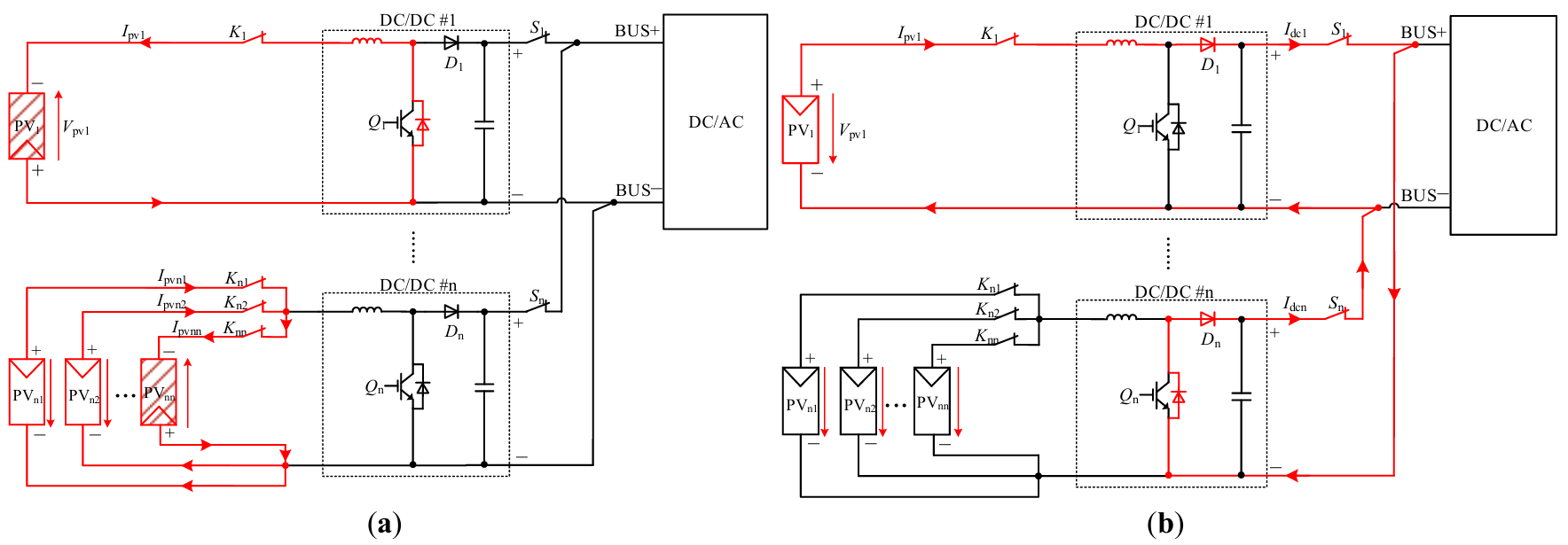
Figure 1. Current loops of PV system when a reverse polarity fault occurs on (a) PV side and (b) DC-bus side. The arrow pointing from the positive to the negative terminal of a PV string indicates the direction of the voltage drop across that string, while the other arrows in the circuit denote the current direction. Additionally, the shaded PV strings represent those with the reverse polarity fault, the red solid lines highlight the current flow paths, and the black dotted box include the components that make up the DC/DC converter circuit.
As shown in Figure 1a, for converter DC/DC #1, when the polarity of PV1 is reversed and DC switch K1 is closed, the output voltage polarity of PV1 is reversed, thereby causing the output current Ipv1 to flow in reverse through the body diode of switch Q1. This reverse current may damage the body diode, causing the system to malfunction. To prevent this, the reversal of both voltage and current is utilized as the diagnostic signal for implementing reverse polarity protection in this single-PV topology.
For converter DC/DC #n, when the polarity of string PVnn is reversed, and DC switches Kn1 to Knn are closed, the normal string’s currents flow toward PVnn instead of the converter DC/DC #n. The primary reason is that PVnn’s output voltage polarity is reversed relative to the normal strings, resulting in a low-impedance short-circuit path between them. According to the principle that current preferentially flows along the path with the lowest impedance, the current generated by the normal strings will be primarily diverted through this fault path, which has a much lower impedance than the input of the converter DC/DC #n. Figure 2 presents the current–voltage (I–V) characteristics of both normal and reversed strings.
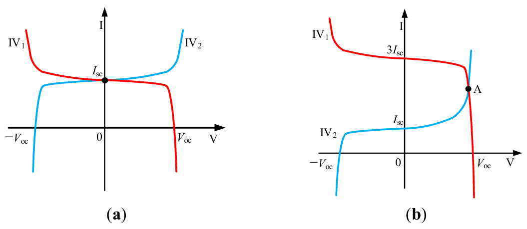
In Figure 2a, for n = 2, the I–V curves of the normal and reversed strings are denoted as IV1 and IV2, respectively. The system operates under short-circuit conditions at (0, Isc), where the reversed string remains undamaged. In Figure 2b, for n = 4, the combined I–V curve of three normal strings is represented by IV1, while IV2 gives that of the reversed string. The intersection of these curves at operating point A corresponds to an elevated current level, implying that the reversed string will be damaged. Therefore, multi-string parallel PV systems must also include reverse polarity protection. The electrical signatures manifested during the fault are used to design such protection, specifically the reversal of voltage/current polarity in the faulty string and a current magnitude equal to the sum of the currents from all normal strings.
Figure 1b illustrates the current loop with a reverse polarity fault on the DC-bus side. When the polarity of DC/DC #n’s output is reversed, the current Idc1 to Idc(n−1) from converters DC/DC #1 to DC/DC #(n−1) flows through the DC bus to the body diode of Qn in DC/DC #n instead of the inverter DC/AC, due to the lower impedance path. However, this current may cause overcurrent damage to Qn’s body diode.
It is worth noting that the direction of the current Idcn flowing into or out of the terminals of the faulty converter DC/DC #n remains unchanged from normal operation; only the magnitude increases abnormally. In comparison to a PV side reverse polarity fault, a DC-bus side fault shows fewer electrical signatures, primarily an abnormal current amplitude. As a result, protection must be implemented without interfering with normal system operation, which makes its design more difficult.
Regarding all the aforementioned reverse polarity faults, a variety of reverse polarity protection schemes have been developed. Detailed discussions of these strategies are provided in the following sections.
3. PV Side Reverse Polarity Protection Methods
This section discusses PV side reverse polarity protection methods. The protection methods are divided into two categories based on their activation timing and fundamental goal: reactive activation protection and preventive activation protection.
Reactive activation protection is a post-fault mitigation strategy. It works after the DC switch is turned on, sensing or detecting fault signals such as an abnormally high reverse current or voltage. When such a signal is detected, the protective unit is activated, or the DC switch is controlled to turn off, thereby interrupting the fault path. Its primary goal is to respond to and isolate a previously detected fault.
In contrast, preventive activation protection is a pre-fault prevention strategy. This method actively verifies the polarity connection before turning on the DC switch. Only after the polarity is confirmed to be correct does the DC switch turn on, allowing the system to start up. Thus, the main goal is to prevent the generation of reverse-polarity fault current at the source.
3.1. Reactive Activation Protection
The reactive activation protection schemes are classified into hardware-based and software-based solutions according to the means of implementation. Although both take the “detects and responds” principle, their fault detecting and actuation mechanisms differ. Hardware-based solutions make use of protective units that activate when a fault signal appears, preventing the current from flowing. On the other hand, software-based solutions, once a sensor detects a fault signal, interrupt the fault current by turning off the DC switch.
3.1.1. Hardware-Based Solutions
Hardware-based solutions require adding protection units to the system. Three conventional protection approaches are currently in use: fuse-based protection, diode-based protection, and MOSFET-based protection. The explanations in this subsection are based on the system topologies described in Section 2. Specifically, the fuse-based protection, which is only applicable to multi-string parallel topologies, will be explained using the corresponding topology. In contrast, diode- and MOSFET-based protection, applicable to both single- and multi-string parallel PV systems, will be discussed using the single-string topology for clarity, with their applicability to multi-string configurations explicitly stated.
Fuse-Based Protection
Figure 3 depicts a fuse-based reverse polarity protection circuit suitable for multi-string parallel PV systems, as well as its current path when a reverse polarity fault occurs [21,22,32]. In this circuit, a fuse is connected in series to both the positive and negative conductors of each PV string branch, as shown in Figure 3a.
When one of the paralleled PV strings has its polarity reversed, a low-impedance fault loop forms within that branch, as described in Section 2. Under this condition, the output currents from all other normally operating parallel PV strings converge and flow through the fuses FUSE1n and FUSE2n in the faulty branch PVn, as shown in Figure 3b. This combined current, which is significantly greater than the current of a single string, is sufficient to quickly blow the fuses FUSE1n and FUSE2n, breaking the fault loop and providing protection [33].
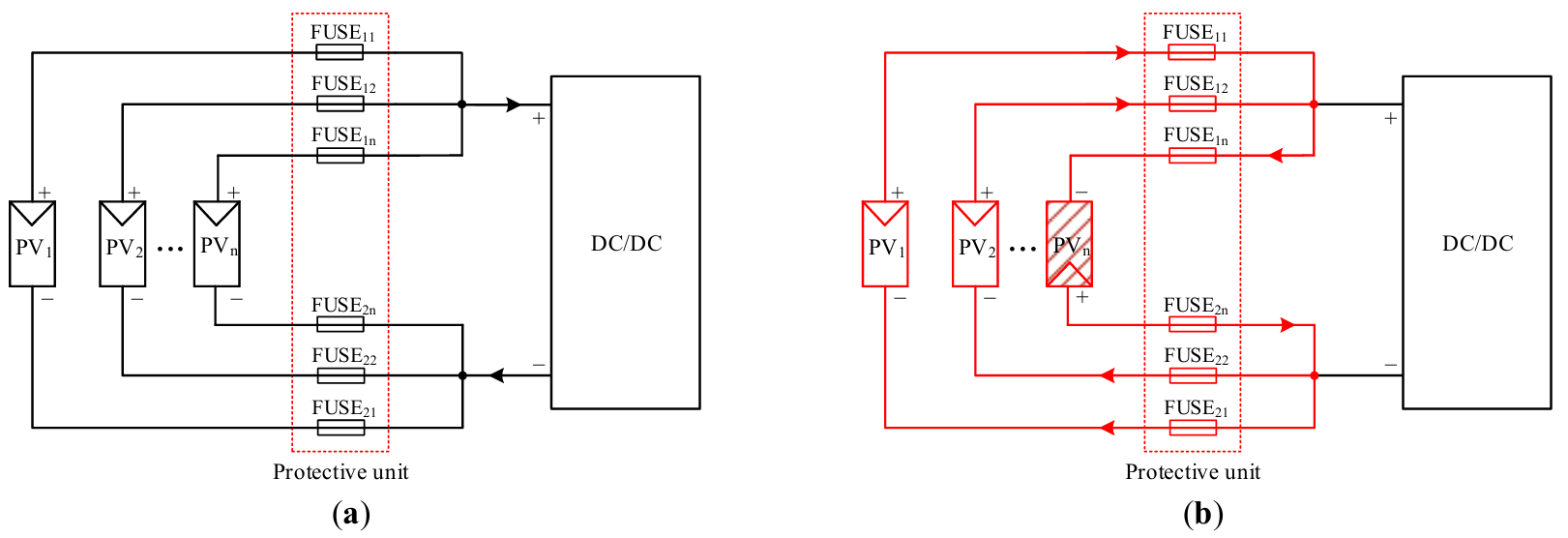
Figure 3. Fuse-based protection circuit for a multi-string parallel PV system under reverse polarity fault: (a) topology and (b) current loop when string PVn’s polarity is reversed. The arrows, shading, and red solid lines follow the same definitions as in Figure 1, and the red dotted box encloses the components that form the protective unit.
This approach eliminates the need for current sensing and controller intervention. However, there are some inherent limitations [34,35,36]. (1) The added fuses may need manual replacement, which can raise maintenance costs. (2) The fuse melting process requires a period of time, and short-circuit currents can damage the body diode in switching device Q1, reducing system reliability. (3) This method is completely dependent on a multi-PV-string parallel topology. In a single-string PV system, the reverse polarity fault current is limited to the short-circuit current of that specific string. The fuse’s rated current is typically set higher than the short-circuit current of a single PV string, so it cannot be blown, rendering the protection scheme ineffective.
From a commercialization perspective, the fuse-based approach requires minimal additional hardware cost, as it can utilize the existing DC fuse module already employed for overcurrent protection in the system. However, its practical commercial adoption is highly limited, especially in medium- to large-scale plants or in scenarios that demand high reliability. This is primarily due to its inherent drawbacks: the need for manual replacement after operation and the inability to automatically distinguish reverse-polarity faults from other overcurrent events. Consequently, this scheme is only found in cost-sensitive, small-scale, or outdated system designs and is strictly applicable to multi-string parallel PV topologies.
Diode-Based Protection
Driven by the limitations of fuse-based protection and facilitated by advances in semiconductor power devices, diode-based schemes have emerged as an alternative for reverse polarity protection. Figure 4 illustrates several diode-based reverse polarity protection circuits for a single PV string system. Figure 4a depicts a conventional circuit that employs a series-connected diode D1 on the DC side, which uses unidirectional conduction for reverse polarity protection [23,24,37,38,39].
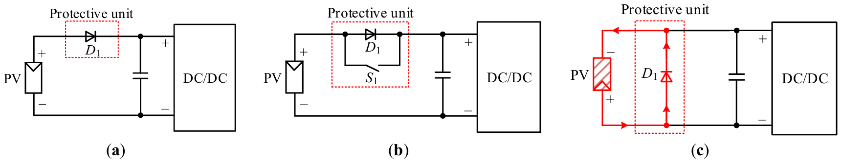
Figure 4. Diode-based reverse polarity protection circuits for a single PV string system: (a) conventional series-diode, (b) optimized series-diode, and (c) shunt-diode topology. The arrows, shading, and red solid lines follow the same definitions as in Figure 1, and the red dotted box follows the same definition as in Figure 3.
When the polarity of the PV string is reversed, diode D1 cannot conduct, effectively blocking the reverse current path [40,41,42]. While structurally simple, this method causes power loss due to D1’s forward voltage drop during normal operation, leading to thermal effects.
A modified approach is proposed in [43,44] by using a parallel-connected switch across the diode. As illustrated in Figure 4b, during normal operation, switch S1 is turned on to bypass the diode D1, thereby eliminating its conduction losses.
Paper [45] proposes an alternative protection method based on a bypass diode. Figure 4c shows the protection circuit of this method and its corresponding current loop when a reverse polarity fault occurs. Diode D1 is connected in reverse parallel across the PV string. During normal operation, D1 remains reverse biased. Under reverse polarity, as shown in Figure 4c, D1 becomes forward-biased, resulting in a short-circuit path that prevents reverse current flows to the DC/DC or DC/AC circuits. For visual polarity indication, the diode can adopt light emitting diodes (LEDs) instead of conventional diodes [46,47]. Overall, this approach has a simple structure, eliminating control circuitry while remaining low-costs [48,49].
It is worth noting that for multi-string parallel PV systems, the aforementioned methods can be expanded by individually configuring the corresponding diode-based protection unit for each PV string branch.
The previously mentioned diode-based schemes differ significantly in terms of commercial viability. The bypass diode configuration has become one of the most common hardware protection methods in small-to-medium-scale PV systems due to its simple structure, low cost, and elimination of control circuitry. In contrast, the series-connected diode method, while simple in concept, introduces persistent conduction loss during normal operation, lowering system efficiency and increasing thermal management costs; this inherent disadvantage severely limits its use in commercial products. The improved series diode scheme, which eliminates conduction loss via a parallel switch, adds control complexity and cost, reducing its commercial viability.
MOSFET-Based Protection
Aiming to mitigate the inherent additional power loss associated with the series-diode method, alternative schemes employing MOSFETs with significantly lower conduction losses have been proposed. Figure 5 illustrates a protection circuit utilizing MOSFET switching characteristics [25,26,27,50] for a single PV string system. The protection unit is made up of a series-connected MOSFET Q1 in the PV string path. Under the correct polarity, Q1 is turned on with the voltage divider network formed by resistors R1 and R2. When the polarity of the PV string is reversed, diode D1 becomes reverse-biased, disabling the voltage divider and causing Q1 to turn off, which can effectively block reverse current [51].
Similar to the diode-based protection method, the MOSFET-based protection can be applied to multi-string parallel PV systems by configuring a separate protection unit for each PV string branch.
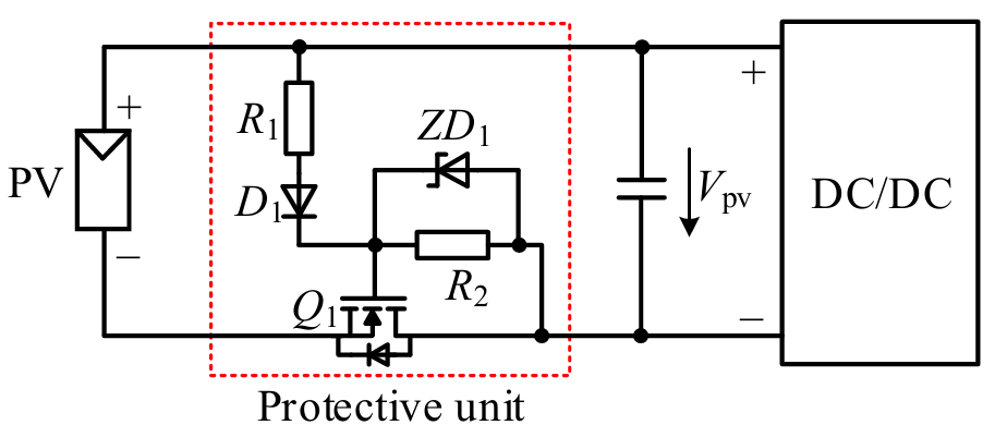
This solution uses PV output voltage to drive MOSFETs without the need for additional control circuits. Compared to conventional series-diode approaches, it offers two main advantages: (1) significantly lower conduction loss due to the MOSFET’s low on-resistance, and (2) compact system design using surface-mount MOSFETs while maintaining thermal performance [52,53]. Nevertheless, it is associated with a higher cost than the series-diode scheme.
The MOSFET-based protection scheme is a viable commercial option for low-loss reverse-polarity protection in PV systems, and it is suitable for a variety of topologies. Notably, patent barriers associated with existing alternative methods have, to some extent, fuelled topology innovation and driven the design of MOSFET-based solutions to circumvent intellectual property restrictions. Nonetheless, the practical application of this scheme requires consideration of inherent challenges such as drive requirements and potential cost increases.
3.1.2. Software-Based Solutions
Unlike hardware-based solutions, software-based solutions do not require additional protection units. The software solutions monitor the system’s electrical parameters to determine the polarity of PV strings. When a reverse-polarity fault is detected, the DC switch can be switched off to provide protection.
Given the different current paths in single- and multi-string parallel systems during reverse polarity, the corresponding protection methods for each configuration are different, which are shown as follows.
Reverse Polarity Protection for a Single PV String
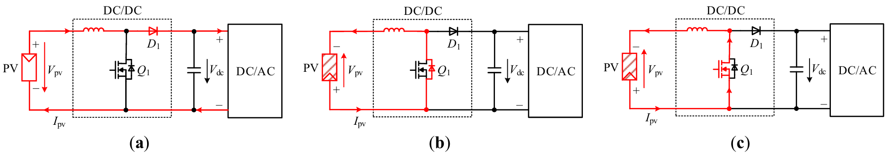
This solution achieves reverse polarity identification by monitoring the PV string’s output voltage Vpv and current Ipv. Figure 6 depicts the current loop under three scenarios: normal polarity, reverse polarity condition, and MOSFET activation under reverse polarity. As shown in Figure 6a, during normal operation, Vpv remains positive, with Ipv flowing to the DC/DC and DC/AC circuits. Under reverse polarity fault as shown in Figure 6b, Vpv becomes negative with a reduced magnitude, while Ipv reverses through Q1’s body diode, resulting in a closed loop. When a negative Vpv or reversed Ipv is detected, the system determines that the PV string is in reverse polarity.
It is noted that prolonged Ipv flowing through Q1’s body diode may cause damage to the switch [54]. Therefore, the controller turns on Q1, diverting current through Q1’s channel rather than its body diode due to Q1’s lower conduction voltage, which are shown in Figure 6c [55]. Then, the DC switch is turned off, ensuring complete protection.
Software-based solutions provide a cost advantage over hardware methods, but they have a protection delay due to the need to detect faults first. This delay not only increases the danger of device damage but also requires reliability testing and risk assessment within the target system architecture prior to deployment. Consequently, such methods are rarely the chosen choice in safety-critical commercial products.
Reverse Polarity Protection for Parallel PV Strings
In multi-string parallel PV systems, reverse polarity protection can be achieved by monitoring relationships of different PV strings’ currents.
Figure 7 presents an example. As shown in Figure 7a, for normal polarity connections, all parallel strings generate currents Ipv1 to Ipvn with consistent direction and magnitude.
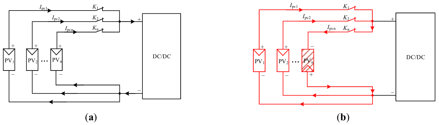
Figure 7b shows that when the polarity of string PVn is reversed, normal string currents are diverted to PVn rather than the DC/DC converter. As a result, the current Ipvn runs in the opposite direction as the other PV strings’ output currents, and its value equals the sum of those currents [56].
From above, the system can continuously monitor the direction and magnitude of current in each string. A reverse polarity fault is confirmed when a string exhibits both reversed current direction and abnormally increased magnitude. Then, the corresponding DC switch is switched off for the faulty string.
It is worth mentioning that the voltage across DC switches needs to withstand twice the PV open-circuit voltage. Under these conditions, turning off the switch directly creates a significant arcing risk [57,58]. Therefore, voltage clamping and spike absorption methods are introduced in [59,60] and [61], respectively. Both solutions are illustrated in Figure 8.
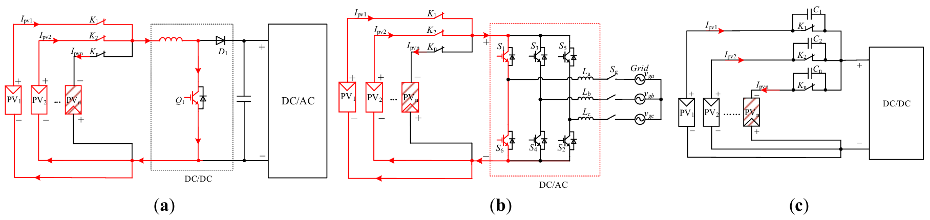
Figure 8. Overvoltage suppression solutions, (a) DC/DC converter switch is turned on, (b) inverter phase-A leg switches are turned on, and (c) voltage spike absorption circuit. The arrows, shading, red solid lines and black dotted box follow the same definitions as in Figure 1, and the red dotted box include the components that make up the DC/AC converter circuit.
As illustrated in Figure 8a,b, when the polarity of a PV string is reversed, either the DC/DC converter’s switch Q1 or all switches S1 and S6 in one inverter bridge leg are turned on [59,60]. This action limits the PV voltage to the switch’s conduction drop level. Therefore, the voltage difference across the DC switch is significantly reduced, allowing it to be safely turned off. As illustrated in Figure 8c, paper [61] proposes connecting a capacitor in parallel at each DC switch. The capacitors absorb turn-off voltage spikes due to their inherent voltage continuity property, allowing safe switch operation within the rated voltage limits [62].
Furthermore, multiple PV strings can share common switches to reduce costs. Figure 9 uses an example of five parallel-connected PV strings to illustrate various wiring configurations between the strings and the switches.
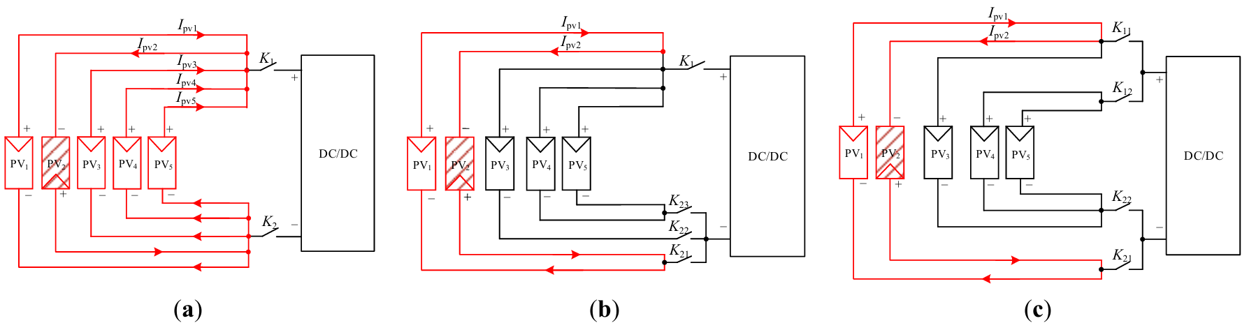
As shown in Figure 9a, PV1 through PV5 share a common positive switch K1 and a common negative switch K2. When the system detects reverse current from PV2, it turns off switches K1 and K2. However, the output currents from normal strings PV1, PV3, PV4, and PV5 continue to flow to PV2 via parallel paths, resulting in overcurrent damage to PV2.
To address this issue, Refs. [56,63] and [64,65,66] proposed two improved solutions that involve optimizing the connection between PV strings and DC switches, as shown in Figure 9b and Figure 9c. These solutions ensure that no more than two strings remain in parallel after DC switches are turned off.
Figure 9b depicts the first solution, which employs a shared positive switch, with negative switches allowing up to two parallel PV strings [56,63]. After switches are turned off, only PV1 and PV2 remain parallel, while the other strings are isolated. As a result, current flows from PV1 to PV2 while remaining within acceptable limits, preventing overcurrent damage. However, switch K1’s current-carrying capacity restricts the total number of parallel PV strings.
The second solution, shown in Figure 9c, proposes a flexible connection architecture [64,65,66] that overcomes the current-carrying limit and allows an unlimited number of parallel PV strings. From it, PV1 and PV2 are paralleled, while PV4 and PV5 form another group. PV3 has a unique cross-connection: the positive terminal connects to the PV1–PV2 group, while the negative terminal connects to the PV4–PV5 group. Although PV1, PV2, and PV3 share a positive switch, the negative switching configuration ensures that only PV1 and PV2 are paralleled after switch deactivation, thereby containing the fault current. Meanwhile, because the current through each switch does not exceed the combined output of three PV strings, the design theoretically allows for unlimited parallel expansion.
The above solutions rely on auxiliary power to detect reverse polarity. However, DC-powered auxiliary power fails during string polarity reversal conditions. Therefore, papers [67,68] propose a priority power supply scheme. A protection unit connects between PVn and the DC/DC circuit. When the PVn polarity is correct, the unit is activated manually, where the auxiliary detection system can be powered up. Therefore, the proposed unit effectively addresses system power challenges. However, it is noted that if PVn reverses, the proposed unit cannot be activated.
Similar to a single-string PV system, software-based protection in multi-string parallel configurations is low-cost but has the inherent limitation of response delay. As a result, in commercial applications, such schemes are rarely the preferred choice for high-reliability scenarios; their applicability is often limited to contexts with greater tolerance for cost and greater control flexibility.
3.2. Preventive Activation Protection
Unlike reactive activation protection methods that work on a “detects and responds” basis after the DC switch is turned on, the strategies in this section use preventive activation protection, which works on a “verifies and permits” principle. This entails verifying the polarity of PV strings before the DC switch is turned on, with energization occurring only after correct polarity is confirmed. The protection schemes are also classified into hardware- and software-based solutions based on their implementation.
3.2.1. Hardware-Based Solutions
The difference between hardware-based solutions is in their DC switching drive mechanisms. Based on this distinction, protection schemes can be classified into two types: independent coil driving protection and hybrid driving protection.
Independent Coil Driving Protection
In this method, each PV string has a DC switch, which is controlled by its own independent coil drive circuit [69,70,71]. Figure 10 depicts two typical hardware circuit implementations for this approach.
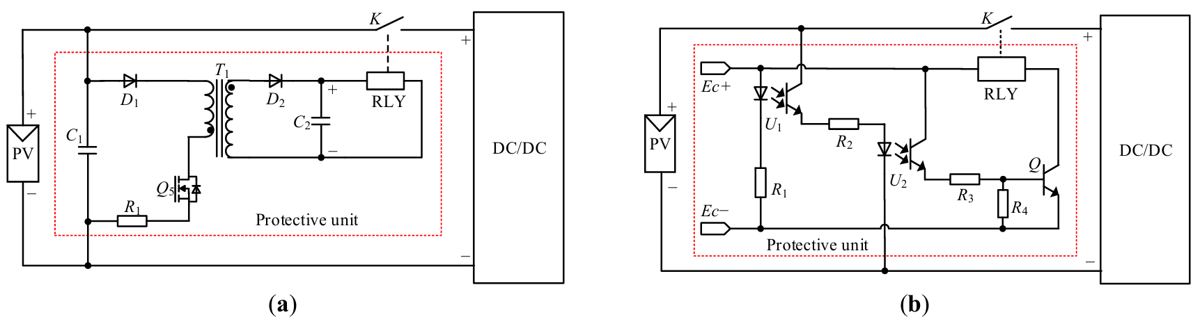
Figure 10a shows that the coil drive circuit uses an auxiliary power supply design [69,70]. Its reverse polarity protection function is accomplished by controlling relay operation based on the output state of the auxiliary power supply. When the PV string is connected with the correct polarity, the auxiliary supply is energized, exciting the relay coil and creating a conducting path in the main circuit. Conversely, under reversed polarity conditions, diode D1 becomes reverse-biased and remains off, preventing the auxiliary power supply from functioning. As a result, the relay coil remains de-energized, thus providing effective fault isolation. However, because the state of the DC switch is determined solely by the PV string, with no involvement from the system controller, this configuration prevents the switch from turning off in response to other types of faults.
An enhanced coil driving circuit implemented with multiple optical couplers is presented in Figure 10b to bring the switch under system control [71]. The operating principle involves the coordinated action of the optical coupler U1 and U2 to simultaneously detect both PV string polarity and the relay control signal. The relay closure occurs only when correct polarity is confirmed, and a turn-on signal is received concurrently.
As depicted in Figure 10b, upon receipt of a relay activation signal at terminals Ec+/Ec−, the primary side of U1 conducts. If the PV string exhibits correct polarity, the secondary side of U1 becomes active, thereby triggering the operation of U2. This subsequently drives the relay closure via transistor Q. In contrast, under reverse PV string polarity, the diode on the primary side of U2 becomes reverse-biased. Consequently, the relay remains de-energized, thereby ensuring reverse polarity protection.
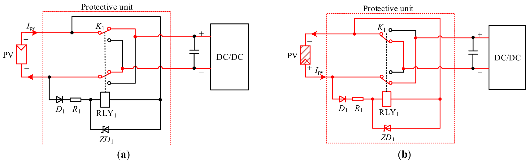
The previous protection schemes require manual intervention to correct polarity after a reversed PV connection is detected. Papers [72,73] present an automatic PV string polarity switching method that eliminates the need for human involvement, thereby ensuring uninterrupted system operation and improved maintenance efficiency.
Figure 11 illustrates the operational principles of the protection unit under correct and reversed PV polarity conditions. Designed to enable automatic polarity switching, the unit comprises primarily a double-pole double-throw relay K1, along with a diode D1, a current-limiting resistor R1, and a Zener diode ZD1. Under correct polarity conditions, as shown in Figure 11a, D1 remains reverse-biased and non-conducting, allowing switch K1 to connect to the upper terminals and thereby establish the main circuit connection. Conversely, under reversed polarity conditions illustrated in Figure 11b, D1 becomes forward-biased and conducts, energizing the driving coil. This actuates switch K1 to commutate to the lower contact terminals. Through this autonomous operation, the system achieves reliable self-correction of polarity, maintaining continuous power delivery without interruption [72].
Additionally, a break-before-make switching strategy is introduced in [73]. This method incorporates an additional controllable switch on the PV side. When a reverse current is detected, the controller opens this switch to prevent the current path. Subsequently, switch K2 is activated to perform the polarity reversal. This zero-current switching strategy effectively prevents arcing, thereby significantly improving system reliability.
All methods described in this section serve as preventive activation protection, ensuring a high level of safety. However, in multi-string parallel PV systems, implementing the protection unit described in this section for each DC switch incurs additional costs. As a result, this solution is better suited for small-scale PV systems, whereas its higher cost may prevent widespread adoption in large-scale installations.
Hybrid Driving Protection
A hybrid driving protection has been developed to reduce the cost of independent coil driving in multi-string PV systems. It relies on a shared protection unit and coordinated driving of the DC switch across multiple strings to provide reverse polarity protection. Figure 12 depicts a typical circuit implementation, which includes a polarity protection circuit with a dual-winding magnetic core structure and illustrates current paths under both normal and reverse polarity fault conditions [74,75].
As shown in Figure 12a, the positive conductors of two PV strings are wound in opposite directions around a common core. Under proper polarity, currents Ipv1 and Ipv2 flow in opposite directions through the windings. Their induced electromagnetic forces cancel out in the core, allowing switch K to remain turned on. Figure 12b illustrates that when the polarity of PV2 is reversed, the direction of the current Ipv2 reverses correspondingly. The electromagnetic forces of Ipv1 and Ipv2 are combined together, which can produce enough magnetic force for switch K to turn off.
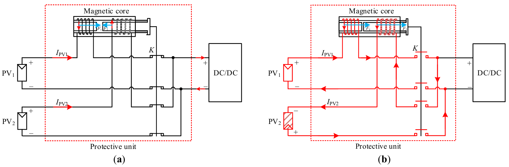
Figure 12. Magnetic core-based polarity protection circuit under reverse polarity fault: (a) topology and (b) current loop when string PV2’s polarity is reversed. The arrows, shading, and red solid lines follow the same definitions as in Figure 1, and the red dotted box follows the same definition as in Figure 3.
According to the analysis presented above, this method has several significant drawbacks. First, it only applies to multi-string parallel PV systems. Furthermore, a reverse-polarity fault in any single string disables all switches, preventing even normal strings from functioning. Although the shared-drive design reduces cost compared to using individual protection units per switch, common components like a shared magnetic core remain expensive.
Commercially, such hardware solutions are frequently less optimal for large-scale PV systems due to cost considerations. In contrast, for small-scale systems, the independent coil-drive protection scheme is more practical due to its simplified design.
3.2.2. Software-Based Solutions
This method determines the polarity of each PV strings by measuring its open-circuit voltage or a voltage that is proportional to open-circuit voltage, while the DC switch is turned off and no closed circuit loop exists [76,77,78]. Essentially, it is a voltage-based software protection strategy.
The corresponding hardware circuit and the defined voltage polarity are illustrated in Figure 13, with the open-circuit voltage serving as the example case. From it, the voltage sensors measure the open-circuit voltage of each PV string and send the information to the controller. Based on the detected voltage polarity, the controller makes decisions and outputs switching control signals. Strings PV1 to PV(n−1) are connected with correct polarity, resulting in positive measured voltages. As a result, the controller closes the corresponding DC switches K1 to K(n−1). In contrast, string PVn is connected with reversed polarity, resulting in a negative voltage measurement, −Vpv. Consequently, the controller maintains switch Kn in the open state, thereby isolating the faulty string and ensuring protection against reverse polarity.
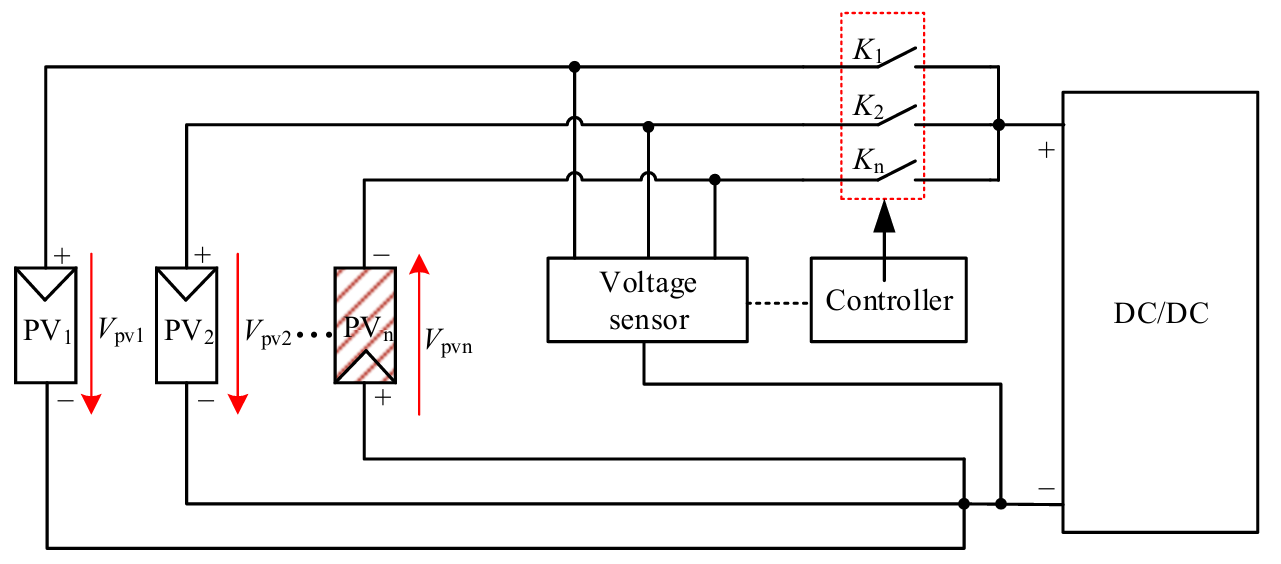
This method is commonly used because it takes advantage of existing voltage sensors in PV systems. By only adding control logic, it provides a secure and straightforward implementation. It is also topology-independent, which ensures wide applicability. However, as with all software solutions, response times are slower than those of hardware protection. Nonetheless, unlike reactive activation protection, the slower response does not jeopardize system safety because the protection action occurs before the main power path is activated. Given these trade-offs, software-based preventive activation protection is widely used in commercial systems, particularly large-scale PV plants.
3.3. Protection Methods Evaluation on the PV Side
Table 1 presents a systematic summary of reverse polarity protection strategies on the PV side in PV systems, which are divided into reactive activation protection and preventive activation protection based on the implementation stage.
Table 1. Evaluation of different methods.
|
Stage of Implementation |
Means of Implementation |
Method |
Advantages |
Limitations |
Commercialization |
|---|---|---|---|---|---|
|
Reactive activation protection |
Hardware-based solutions |
Fuse-based protection |
Simple structure |
High maintenance, slow response, and unsuitable for single PV string systems |
Low |
|
Diode-based protection |
Simple structure and low cost |
Requires optimization to reduce conduction loss |
High(bypass topology)/Low(series topology) |
||
|
MOSFET-based protection |
Low Conduction Loss |
Requires drive network and higher cost than diode-based protection |
High |
||
|
Software-based solutions |
Voltage/current detection protection |
No additional hardware required, and direct fault identification |
Slower response than hardware-based solutions and potential for arc faults in multi-string systems |
Low |
|
|
Preventive activation protection |
Hardware-based solutions |
Independent coil driving protection |
Higher safety and increased system reliability compared to reactive activation protection |
Higher hardware cost and larger size than reactive activation protection |
Medium |
|
Hybrid driving protection |
Higher cost and larger size; not for single PV string systems; simultaneous switching |
Low |
|||
|
Software-based solutions |
Voltage detection protection |
Slower response than hardware-based solutions |
High |
Reactive activation protection is used after a fault occurs and can be classified as hardware-based or software-based depending on how it is implemented. Hardware-based solutions include fuse-based protection, which has a simple structure but requires high maintenance, exhibits slow response, and is not suitable for single PV string systems; diode-based protection, which has a simple structure and is inexpensive but requires optimized design to reduce conduction losses; and MOSFET-based protection, which offers low conduction loss but necessitates additional drive circuits and is more expensive than diodes. At this stage, the software-based solution is voltage/current detection protection, which has the advantage of not requiring additional hardware and enabling direct fault identification. However, its response time is slower than hardware solutions, and it may introduce arc faults in multi-string systems.
Preventive activation protection is intended to prevent faults, thereby increasing system safety and reliability. Its hardware-based solutions are primarily comprised of independent coil driving protection and hybrid driving protection, both of which have the disadvantages of higher hardware costs and larger size compared to reactive activation protection, which is unsuitable for single PV string systems and requires simultaneous operation of all switches. At this stage, the software-based approach is voltage detection protection, which responds more slowly than hardware-based solutions.
Choosing reverse polarity protection methods for PV systems requires balancing cost, reliability, efficiency, and other considerations for commercial viability. Among reactive activation protection, the diode-bypass method is frequently used due to its simplicity and inexpensive cost. MOSFET-based protection is also a popular commercial option due to its low loss. Other techniques, on the other hand, have low commercial acceptance due to intrinsic disadvantages such as maintenance requirements, power losses, or reliability concerns.
Within preventive activation protection, software-based solutions are widely used due to their cost-effectiveness and scalability. Independent coil driving protection is suitable for small-scale systems due to its simplicity, but hybrid driving protection are not widely used due to its limitations.
4. DC-Bus Side Reverse Polarity Protection Methods
Reverse-polarity faults on the DC-bus side primarily originate from miswiring between DC/DC converter outputs and bus bars during on-site installation. Fully integrated and factory-prewired small-scale systems require minimal field wiring, reducing the risk and need for protection. In contrast, manual wiring poses a substantial danger of reverse polarity connection for medium- to large-scale systems requiring on-site installation. Therefore, this section focuses on reverse polarity protection solutions for the DC bus side.
The protection strategies can be classified into hardware-based and software-based solutions. It is important to note that all methods require a current path to be established between at least one PV string and the bus in order to achieve reverse-polarity protection. This implies that the protection at the DC-bus is inherently a reactive activation mechanism.
4.1. Hardware-Based Solutions
Considering the characteristics of reverse polarity fault signals on the DC-bus side and the design constraint of not interfering with normal operation, the number of viable hardware solutions is less than on the PV side. Hardware solutions used on the PV side, such as fuses and series-connected diodes/MOSFETs, are no longer suitable for the DC-bus side due to high conduction losses or disruption of normal system operation. As a result, practically feasible methods can be divided into two categories: diode bypass protection and additional capacitor voltage polarity detection method.
4.1.1. Diode Bypass Method
As described in Section 2, if the output of a DC/DC converter is reversed and connected to the DC-bus, a low-impedance fault loop forms. As shown in Figure 14a, the output currents from all other normally operating parallel converters, DC/DC #1 to DC/DC #(n−1), converge and flow through the body diode of the Qn in the reversed converter DC/DC #n, subjecting it to severe overcurrent stress and potential damage.
To address this issue, Paper [79] proposes a diode bypass-based hardware protection method. As shown in Figure 14b, the diodes Dt1 to Dtn, each with a lower forward voltage drop and higher current capability than the body diodes Q1 to Qn, are installed antiparallel to the outputs of each DC/DC converter.
When the output of DC/DC #n is reversed, the combined output currents from the other converters flow preferentially through the parallel diode Dtn rather than through the body diode of Qn. This is because Dtn’s lower forward voltage drop allows for a more easily conductive path. As a result, the fault current is redirected, protecting the switch from damage due to overcurrent.
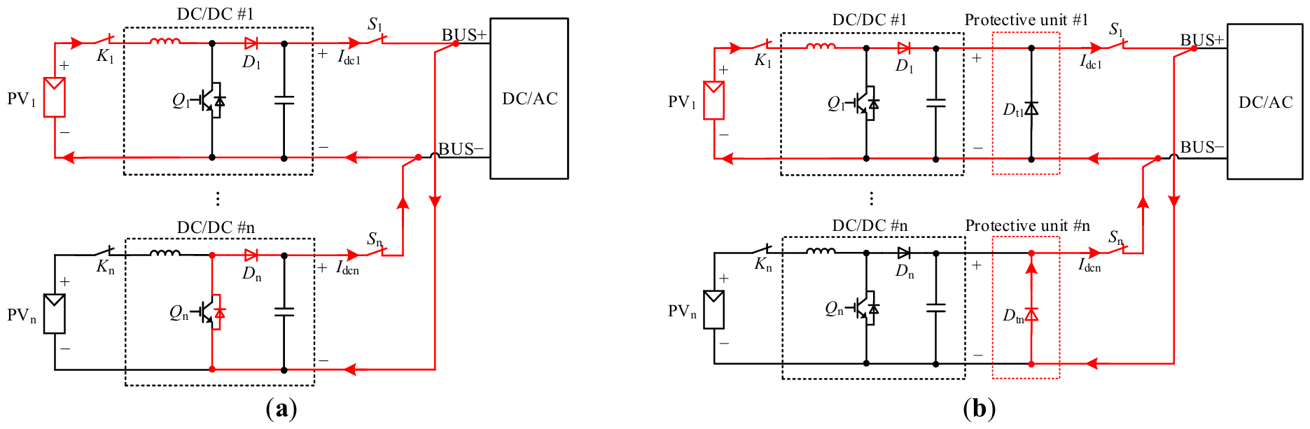
According to this configuration, reverse protection can be achieved by monitoring the current in the parallel diode branch: if current is detected in this branch, it can be determined that the corresponding DC/DC converter has reversed output polarity. To achieve rapid protection and fault isolation, the converter’s output switch can be turned off immediately.
This method is characterized by its low incremental cost and simple circuitry, which only requires the addition of diodes. However, the diodes in the protection unit must have a lower forward voltage drop than the switching transistor’s body diode in order to provide a low-impedance path for fault current. The number of parallel DC/DC converters is limited by the diode’s transient current capability, since the bypass diode in the reverse DC/DC converter must carry the full current from all other DC/DC converters. Commercially, its low-cost advantage makes it suited for residential and small-scale PV systems, while its restricted scalability prevents adoption in large-scale applications.
4.1.2. Additional Capacitor Voltage Polarity Detection Method
A method proposed in [80] addresses the limitation on the number of parallel DC/DC converters in reverse polarity protection by incorporating an additional capacitor as a protection unit, with protection enabled by voltage detection. Figure 15 depicts the additional protection circuit utilized in the proposed method, along with the current paths under both correct and reverse polarity conditions. From it, the protection unit consists of capacitors C1 to Cn, connected in parallel between the DC/DC converter output and the DC-bus.
The protection procedure begins with the operation of one DC/DC converter, such as DC/DC #1, which must be selected to power the DC-bus. At this stage, the switches K1 and S1 are turned on, allowing the string PV1 to supply power to the DC-bus via this converter. Since the other converters have not yet started, the DC-bus charges all capacitors C2 to Cn connected in parallel across it.
As shown in Figure 15a, when all DC/DC converters are properly connected, the polarity of each capacitor aligns with that of the DC-bus, resulting in a positive voltage. When a converter, such as DC/DC #n, is reversely connected to the DC-bus, as illustrated in Figure 15b, its corresponding capacitor Cn charges to a negative voltage due to the reversed polarity, while the remaining capacitors maintain positive voltages. If the first activated converter DC/DC #1 is reversely connected, as shown in Figure 15c, its capacitor C1 is forward-charged by DC/DC #1 and develops a positive voltage, while all other capacitors are reversely charged through the DC-bus and exhibit negative voltages.
In summary, the detection mechanism is based on the voltage polarity of each protection unit after the initial charging phase. When the voltage polarity of one branch differs from that of the others, it indicates a reverse polarity defect in that branch, and the related switch is switched off to provide system safety.
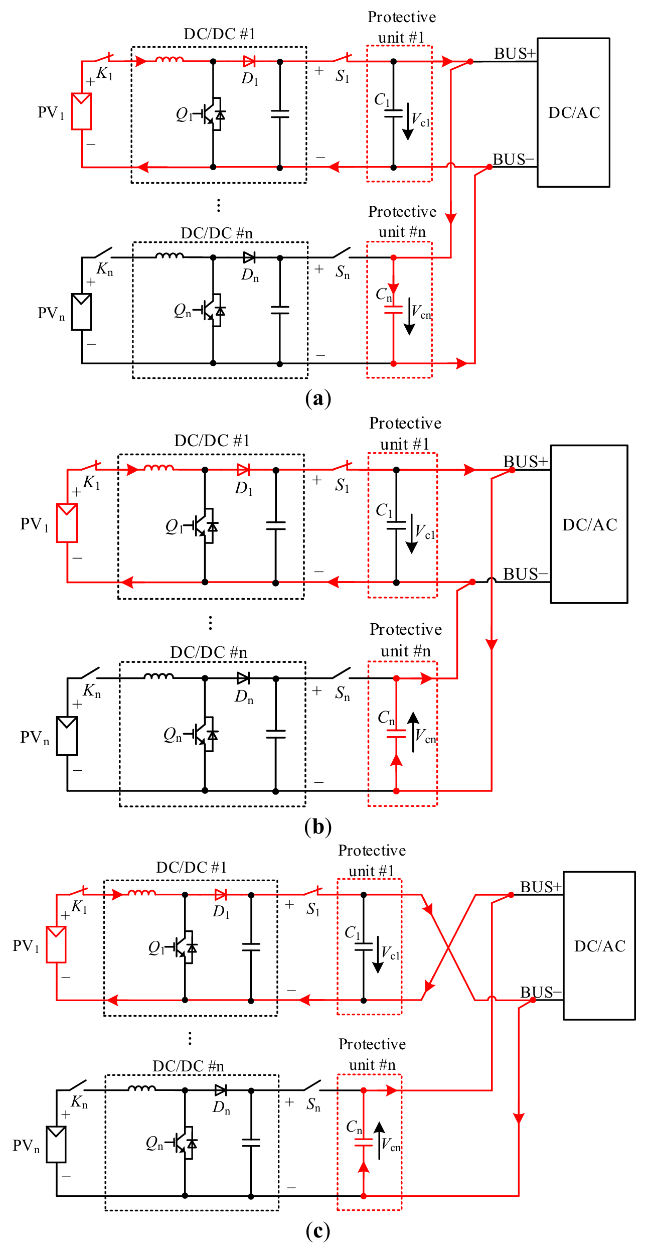
Figure 15. Detection circuit with K1 and S1 are turned on, (a) normal polarity, (b) DC/DC #n reverse polarity, (c) DC/DC #1 reverse polarity. The arrows, red solid lines, and the black dotted box follow the same definitions as in Figure 1 and Figure 5, and the red dotted box follows the same definition as in Figure 3.
As previously discussed, the scalability of the diode bypass method is limited by the transient current capability of the diode. In contrast, the proposed solution activates one DC/DC converter to supply a controlled charging current to the DC-bus and all capacitors, thereby preventing capacitor overvoltage. This makes the method independent of the number of parallel DC/DC converters and thus offers higher scalability compared to the diode bypass approach. However, because the protection action relies on the capacitor charging process, the response time for protection is longer than that of the diode bypass method.
Because of its superior scalability, this approach has interesting commercial applications for medium/large-scale PV systems or scenarios needing flexible extension, particularly in systems with several parallel units. However, due to the higher hardware cost and accompanying control circuitry required, it is best suited for medium-power PV systems with a focus on great scalability and low cost sensitivity.
4.2. Software-Based Solutions
From the above solutions, additional protection units are required. Therefore, paper [81] proposes a software-based algorithm for DC-bus side reverse polarity protection.
As depicted in Figure 1, a reverse-polarity connection in DC/DC #n results in a substantial increase in the current flowing through the corresponding switch, Sn. This method identifies such faults by continuously monitoring the currents of all DC switches. A large divergence, specifically a current that significantly exceeds that of the other branches, indicates a reversed fault in the corresponding DC/DC converter.
Upon fault detection, all switches (Q1 to Qn) are simultaneously activated, as shown in Figure 16. This action effectively short-circuits the PV strings, diverting current away from the DC/DC converters. Consequently, the current through the DC switches (S1 to Sn) drops to zero, allowing them to be safely opened, thereby preventing electrical stress or arcing.
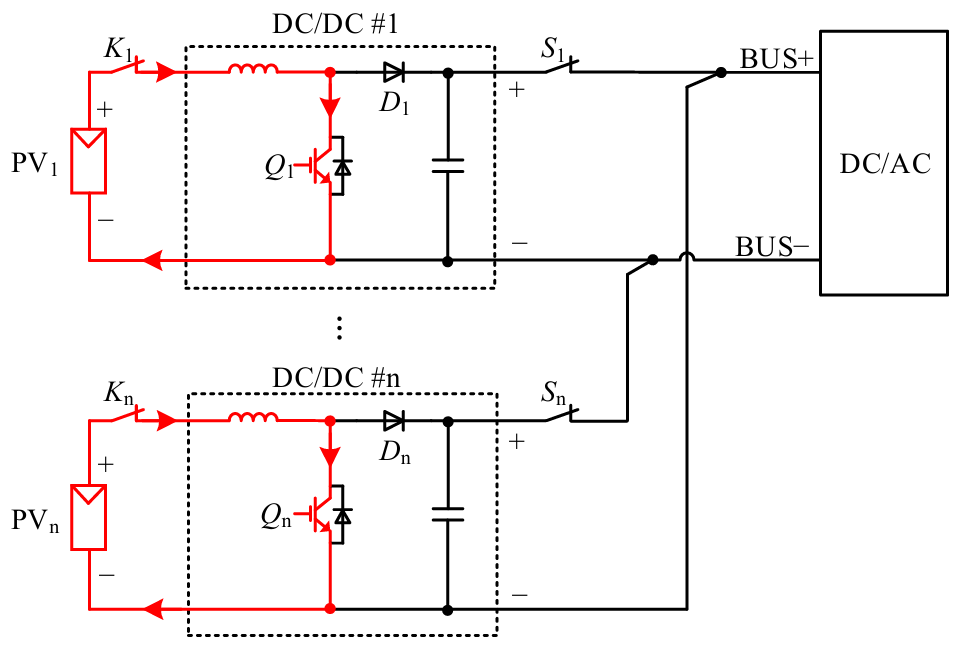
This software-based protection eliminates the need for extra hardware, resulting in cost savings. However, within the detection-to-actuation interval, the fault current remains present in the original circuit, exposing sensitive components to electrical stress. As a result, the necessity to evaluate its reaction delay prior to deployment limits the commercial application of this technology.
4.3. Protection Methods Evaluation on the DC-Bus Side
Table 2 provides a systematic summary of reverse polarity protection strategies on the DC-bus side of PV systems. The methods described all fall under the category of reactive activation protection and are classified as hardware-based or software-based solutions based on their implementation means.
Hardware-based solutions primarily include the diode bypass method and the additional capacitor voltage polarity detection method. The diode bypass method consists of connecting diodes in reverse parallel within each DC/DC branch. This approach is simple to implement, inexpensive, and provides a quick response. However, it must have a lower forward voltage drop than the switching transistor’s body diode in order to provide a low-impedance path for fault current. And the limited current-carrying capacity of diodes restricts the scalability of the number of DC/DC converters that can be connected in parallel. The additional capacitor voltage polarity detection method necessitates the activation of one DC/DC circuit during the system startup phase to charge the DC-bus and the extra parallel capacitors. The polarity of the capacitor voltage is then used to identify a reverse connection fault. While this method is not restricted by the number of the DC/DC converters, it has a relatively slow response time due to the capacitor charging time.
The software-based solution is primarily based on monitoring the current values in each DC/DC branch, which eliminates the need for additional hardware. However, its protection mechanism reacts slowly, posing a safety risk because the fault current continues to flow along the original path until the protective polarity response is engaged.
Based on the above analysis, the selection of reverse polarity protection solutions on the DC-bus side necessitates a comprehensive evaluation of the advantages and limitations of all candidate methods to identify the optimal approach. The additional capacitor voltage polarity detection method has been the most extensively commercialized option due to its scalability and safety. The diode bypass method has economic potential in residential and small-scale PV systems due to its inexpensive implementation costs. While software-based solutions are cost-effective, their commercialization is limited due to safety concerns about reaction times.
Table 2. Evaluation of different methods.
|
Stage of Implementation |
Means of Implementation |
Method |
Advantages |
Limitations |
Commercialization |
|---|---|---|---|---|---|
|
Reactive activation protection |
Hardware-based solutions |
Diode bypass method |
Simple structure, low cost and quick response |
Critical diode selection (the forward voltage must be lower than the body diode of the switch Q) and low scalability |
Medium |
|
Additional capacitor voltage polarity detection method |
High scalability |
Limited response speed (capacitor charging delay) |
High |
||
|
Software-based solution |
Current detection protection |
No additional hardware required |
Safety risk due to slow response |
Low |
5. Conclusions
This paper has presented a comprehensive review of reverse polarity protection technologies in PV systems. A multidimensional framework is proposed to categorize and compare existing methods. This framework is organized around three key criteria: protection location, which determines whether it is implemented on the PV or DC-bus side; implementation stage, which distinguishes between preventive and reactive activation; and implementation means, which categorize approaches as hardware-based or software-based. In addition, each method is evaluated in terms of commercial viability.
Based on this framework, this paper begins by providing a comprehensive review of PV side protection schemes. These are divided into two categories: reactive activation methods and preventive activation methods. Reactive activation schemes respond after fault occurrence. Hardware-based solutions among these, the diode-bypass approach is widely used in small-to-medium-scale systems due to its low cost and simplicity. MOSFET-based protection reduces loss, though it increases complexity and cost. Fuse-based methods are simple and inexpensive but suffer from slow response and maintenance needs, and are unsuitable for single-string systems. Software-based reactive protection avoids extra hardware but is slower than hardware alternatives and may pose security risks. Preventive-activation schemes enhance safety by verifying polarity before startup. Among these, hardware-based solutions are reliable but costly, whereas software-based solutions add minimal hardware at the expense of slower response time. In commercial applications, solutions based on diode bypass and MOSFETs dominate in the reactive activation field, while software-based solutions are more widely used in preventive activation.
Subsequently, the paper focuses on analyzing protection schemes for the DC bus side; all practical schemes are reactive. The diode-bypass hardware solution is cost-effective and fast, but has limited scalability because each diode must withstand the cumulative failure current from all healthy parallel converters. This method is appropriate for smaller-scale systems. The additional capacitor voltage polarity detection method is commonly employed in medium-scale systems, however, its response may be delayed due to capacitor charging. Although software-based current monitoring eliminates the need for additional hardware, it is slower and permits fault current to remain until protection is engaged, making it less suited for safety-critical applications.
In practice, the optimal solution varies depending on the specific situations. The system scale, cost sensitivity, and reliability needs should all be considered during the selection process. Future research should concentrate on components with reduced loss and faster switching, as well as integrated designs that make installation easier while maintaining high dependability at different system scales.
Statement of the Use of Generative AI and AI-Assisted Technologies in the Writing Process
Generative AI was used solely for English grammar polishing.
Acknowledgments
The authors would like to thank the Technical Development Center of Ginlong Technologies Co., Ltd. for their technical assistance and access to the specialized database.
Author Contributions
Conceptualization, W.Z. and L.X.; Methodology, W.Z. and L.X.; Formal Analysis, W.Z., L.X., P.X. and H.C.; Investigation, W.Z. and L.X.; Resources, Y.W.; Data Curation, W.Z. and L.X.; Writing—Original Draft Preparation, W.Z. and L.X.; Writing—Review & Editing, W.Z., Y.W., P.X. and H.C.; Visualization, W.Z. and L.X.; Supervision, W.Z., Y.W., P.X. and H.C.; Project Administration, W.Z., Y.W. and P.X.; Funding Acquisition, Y.W.
Ethics Statement
Not applicable.
Informed Consent Statement
Not applicable.
Data Availability Statement
Data availability is not applicable to this paper as no new data were created or analyzed in this study.
Funding
This work was funded by National Key R&D Program of China (2024YFB3814000) and R&D Program of Zhejiang (2024C01242(SD2)).
Declaration of Competing Interest
The authors declare that they have no known competing financial interests or personal relationships that could have appeared to influence the work reported in this paper. Authors Wenping Zhang, Linyan Xu, Yiming Wang and Po Xu were employed by Ginlong Technologies Co., Ltd. The authors declare that this company was involved in providing access to a publicly available literature database and was not involved in the study design, data collection, analysis, interpretation, and manuscript writing.
References
- Singh R, Yadav VK, Singh M. An improved hot spot mitigation approach for photovoltaic modules under mismatch conditions. IEEE Trans. Ind. Electron. 2024, 71, 4840–4850. DOI:10.1109/tie.2023.3281684 [Google Scholar]
- Dranka GG, Aguiar Ferreira RM, de Alencar ÁP, Leludak JA, Candido R, Pazinatto MDS, et al. A comprehensive audit framework for rural photovoltaic systems: On-site insights and key findings from brazil. Energy 2025, 322, 135436. DOI:10.1016/j.energy.2025.135436 [Google Scholar]
- Zuboy J, Springer M, Palmiotti EC, Karas J, Smith BL, Woodhouse M, et al. Getting ahead of the curve: Assessment of new photovoltaic module reliability risks associated with projected technological changes. IEEE J. Photovolt. 2024, 14, 4–22. DOI:10.1109/jphotov.2023.3334477 [Google Scholar]
- Belhachat F, Larbes C, Bennia R. Recent advances in fault detection techniques for photovoltaic systems: An overview, classification and performance evaluation. Optik 2024, 306, 171797. DOI:10.1016/j.ijleo.2024.171797 [Google Scholar]
- Benjamin Zulu G, Mostefa Khelil DCK, Murairidzi Gotora G, Zahreddine T. Identification of PV fault classes using intelligent method KNN (k-nearest neighbours). Int. J. Res. Sci. Innov. 2024, 11, 1202–1229. DOI:10.51244/ijrsi.2024.1108093 [Google Scholar]
- Faria JPD, Pombo JAN, Mariano SJPS, Calado MRA. Plug-and-play framework for assessment of renewable energy community strategies. IEEE Access 2025, 13, 29811–29829. DOI:10.1109/access.2025.3539533 [Google Scholar]
- Napole C, Derbeli M, Barambones O. Fuzzy logic approach for maximum power point tracking implemented in a real time photovoltaic system. Appl. Sci. 2021, 11, 5927. DOI:10.3390/app11135927 [Google Scholar]
- Samal S, Barik PK, Soni RK, Nayak S. Simulation and experimental investigation of a smart mppt based solar charge controller. Energy Source. Part A 2022, 44, 7748–7763. DOI:10.1080/15567036.2022.2116507 [Google Scholar]
- Szpakowska-Peas E, Filipowicz M. Selected aspects of electronic hardware development and testing for the flight reconfiguration system in accordance with the RTCA DO-160G standard. Aircr. Eng. Aerosp. Technol. 2024, 97, 28–36. DOI:10.1108/aeat-03-2024-0083 [Google Scholar]
- Syulekchieva D, Midyurova B, Mandadzhiev A, Belovski I, Mihalev T, Koleva E. Cyber-physical system for treatment of river and lake water. Eng. Proc. 2025, 104, 65. DOI:10.3390/engproc2025104065 [Google Scholar]
- Dutta S, Bauman J. An overview of 800 V passenger electric vehicle onboard chargers: Challenges, topologies, and control. IEEE Access 2024, 12, 105850–105864. DOI:10.1109/access.2024.3435463 [Google Scholar]
- Zhang YC, Zhang GY. Design of multimodal neural network control system for mechanically driven reconfigurable robot. Comput. Intell. Neurosci. 2022, 2022, 2447263. DOI:10.1155/2022/2447263 [Google Scholar]
- Ramesh K, Gupta SK, Hariharan B, Hayashi Y, Jagadeesan P, Jain A, et al. High-performance and low-noise front-end electronics for grapes-3 muon telescope. Exp. Astron. 2023, 56, 31–47. DOI:10.1007/s10686-023-09898-5 [Google Scholar]
- Abubakar A, Almeida CFM, Gemignani M. Review of artificial intelligence-based failure detection and diagnosis methods for solar photovoltaic systems. Machines 2021, 9, 328. DOI:10.3390/machines9120328 [Google Scholar]
- Wang X, Huang J, Xu Z, Zhang C, Guan X. Real-world scale deployment of hydrogen-integrated microgrid: Design and control. IEEE Trans. Sustain. Energy 2024, 15, 2380–2392. DOI:10.1109/tste.2024.3418494 [Google Scholar]
- Ahmed T, Khan FA, Waqar A, Mehmood S, Shakeel H, Hassan S, et al. Design and implementation of PV fed local UPS inverter. Pak. J. Eng. Technol. 2021, 4, 1–8. DOI:10.51846/vol4iss4pp1-8 [Google Scholar]
- Reis GL, Brandao DI, Oliveira JH, Araujo LS, Cardoso Filho BJ. Case study of single-controllable microgrid: A practical implementation. Energies 2022, 15, 6400. DOI:10.3390/en15176400 [Google Scholar]
- Alanazi MA. Control and monitoring of stand-alone hybrid renewable energy systems. Pol. Energet. 2025, 28, 23–54. DOI:10.33223/epj/202558 [Google Scholar]
- Saleh MU, Deline C, Benoit E, Kingston S, Edun AS, Jayakumar NKT, et al. An overview of spread spectrum time domain reflectometry responses to photovoltaic faults. IEEE J. Photovolt. 2020, 10, 844–851. DOI:10.1109/jphotov.2020.2972356 [Google Scholar]
- Balle M, Xu W, Darras KF, Wanger TC. A power management and control system for environmental monitoring devices. IEEE Trans. AgriFood Electron. 2025, 3, 134–143. DOI:10.1109/tafe.2024.3472493 [Google Scholar]
- Kondratjevs K, Zabasta A, Selmanovs-Pless V. Development of power supply management module for radio signal repeaters of automatic metering reading system in variable solar density conditions. Latv. J. Phys. Tech. Sci. 2016, 53, 14–23. DOI:10.1515/lpts-2016-0002 [Google Scholar]
- Akram M, Lotfifard S. Modeling and health monitoring of DC side of photovoltaic array. IEEE Trans. Sustain. Energy 2015, 6, 1245–1253. DOI:10.1109/tste.2015.2425791 [Google Scholar]
- Ray A, Magod R, Talele B, Alevoor S, Mayhugh T, Bakkaloglu B. An active EMI cancellation technique achieving a 25-db reduction in conducted EMI of LIN drivers. IEEE Trans. Circuits Syst. I Regul. Pap. 2022, 69, 3829–3840. DOI:10.1109/tcsi.2022.3187068 [Google Scholar]
- Babenko VP, Bityukov VK. Protection of battery-powered devices against accidental swap of power supply connections. Russ. Technol. J. 2022, 10, 52–59. DOI:10.32362/2500-316x-2022-10-6-52-59 [Google Scholar]
- Vlasov E, Denisov N, Verbeeck J. Low-cost electron detector for scanning electron microscope. HardwareX 2023, 14, e00413. DOI:10.1016/j.ohx.2023.e00413 [Google Scholar]
- Fernando J. Development and validation of a less expensive and portable PLC module for students training in industrial automation. Electron. ETF 2022, 26, 39–45. DOI:10.53314/els2226039p [Google Scholar]
- Patil S, Bhanuprakash CV, Singh B. Multioutput flyback DC-DC converter for MIL applications. Res. Sq. 2021. DOI:10.21203/rs.3.rs-164476/v1 [Google Scholar]
- Sachin K, Yadav VP, Mukesh AN, Sharma PK, Solanki L. Design and development of PWM based solar hybrid charge controller. In Proceedings of the 2021 IEEE International Conference on Electronics, Computing and Communication Technologies (CONECCT), Bangalore, India, 9–11 July 2021. DOI:10.1109/CONECCT52877.2021.9622645 [Google Scholar]
- Malik A, Haque A, Kurukuru VSB, Khan MA, Blaabjerg F. Overview of fault detection approaches for grid connected photovoltaic inverters. Electron. Energy 2022, 2, 100035. DOI:10.1016/j.prime.2022.100035 [Google Scholar]
- Coşkun O, Eken R, Çevik Ö, Yılmaz G. The effect of ferrite bead on conducted emission in an automotive LED driver module with DC–DC converters. Analog Integr. Circ. Signal Process. 2022, 113, 197–209. DOI:10.1007/s10470-022-02068-1 [Google Scholar]
- Menshikov YA, Popel OS, Tarasenko AB. Photovoltaic array control systems for generating useful products with electricity production as an intermediate stage. Appl. Sol. Energy 2023, 58, 869–875. DOI:10.3103/s0003701x22060111 [Google Scholar]
- Zhang YL, Zhao Y. A Power Supply Circuit Suitable for Inverters. CN Patent 213279144U, 25 May 2021. [Google Scholar]
- Yang H, Liu X. Design of PV charge and discharge controller in insulator monitoring system. In Proceedings of the 2011 2nd International Conference on Artificial Intelligence, Management Science and Electronic Commerce (AIMSEC), Dengfeng, China, 8–10 August 2011. DOI:10.1109/AIMSEC.2011.6011058 [Google Scholar]
- Dsa D, Chinnusamy A, Banavath SN, Carvalho EL. Implementation of protection features for a modular bidirectional solid-state battery disconnector. IEEE J. Emerg. Sel. Topics Power Electron. 2025, 13, 3000–3012. DOI:10.1109/jestpe.2024.3502157 [Google Scholar]
- Mayer C, Baumann M, Eisenmann B, Herzog H-G. A review of electronic fuses: Challenges and opportunities for future vehicular power systems. IEEE Trans. Transport. Electrific. 2025, 11, 8548–8560. DOI:10.1109/tte.2025.3542440 [Google Scholar]
- Baba M, Bin Mohd Nor N, Aman Shiekh M, Alharthi YZ, Shutari H, Faran Majeed M. A review on microgrid protection challenges and approaches to address protection issues. IEEE Access 2024, 12, 175278–175303. DOI:10.1109/access.2024.3458047 [Google Scholar]
- Sun Q, Zhong X, Liu J, Wang F, Chen S, Zhong L, et al. Three-dimensional modeling on lightning induced overvoltage for photovoltaic arrays installed on mountain. J. Clean. Prod. 2021, 288, 125084. DOI:10.1016/j.jclepro.2020.125084 [Google Scholar]
- Festus B, Ugwu NU, Amodu FR, Bassey EN. An improved microcontroller based lead acid battery charger. Int. Conf. Sci. Eng. Environ. Technol. (ICONSEET) 2017, 2, 265–273. DOI:10.13140/RG.2.2.18869.37608 [Google Scholar]
- Sepúlveda-Oviedo EH, Travé-Massuyès L, Subias A, Pavlov M, Alonso C. Fault diagnosis of photovoltaic systems using artificial intelligence: A bibliometric approach. Heliyon 2023, 9, e21491. DOI:10.1016/j.heliyon.2023.e21491 [Google Scholar]
- Hashmi MS, Hashmi MS, Talpur BA, Saood M, Muhammad Z, Akhtar A, et al. The photon sentinel: A light-dependent security system for domestic and professional environments. Int. J. Electr. Eng. Emerg. Technol. 2023, 6, 7–10. Available online: https://oldarchive.ijeeet.com/index.php/ijeeet/article/view/134 (accessed on 30 December 2025).
- Ekoh MO, Ekechukwu IJ, Nwokonko RC. Design and implementation of a remotely operated quadcopter with integrated image capture for surveillance applications: A case study at the university of Nigeria, Nsukka. Int. J. Innov. Sci. Res. Technol. 2025, 10, 1485–1496. DOI:10.38124/ijisrt/25jul057 [Google Scholar]
- Vignesh Pandian R, Sundar Rajan GT. Next generation induction heating: GAN vs. MOSFET based resonant power converter for residential use. I-Manager’s J. Electrical Eng. 2024, 17, 21–43. DOI:10.26634/jee.17.3.20639 [Google Scholar]
- Tan F, Wang JG, Wang F, Li ZP. Photovoltaic Grid Connected Inverter with Reverse Connection Prevention Function and Control Method Therefor. CN Patent 102403888B, 25 December 2013. [Google Scholar]
- Wang JG, Wang F, Li ZP, Tang W, Tan F. Reverse Connection Protection Inverter Circuit. CN Patent 201717802U, 19 January 2011. [Google Scholar]
- Gao YB, Wang J, Shi L. DC/DC Conversion Circuit. EP Patent 3883080B1, 31 July 2024. [Google Scholar]
- Feng JG, Chen CC, Ding J, Zhang Y. Direct Current Joins Conversely Indicating Circuit and Photovoltaic Inverter Circuit Thereof. CN Patent 206041486U, 22 March 2017. [Google Scholar]
- Das B. Module Reliability, Testing and Life Cycle Assessment for Solar Photovoltaic Module. Ph.D. Thesis, Indian Institute of Engineering Science and Technology, Howrah, India, 2024. [Google Scholar]
- Sadeghi J, Choolabi EF, Zare MH. A new topology of unidirectional multistring PV inverter with high frequency AC-Link. In Proceedings of the 2016 24th Iranian Conference on Electrical Engineering (ICEE), Shiraz, Iran, 10–12 May 2016. DOI:10.1109/IranianCEE.2016.7585714 [Google Scholar]
- Dides C, Leyre X. Electronic Connection Device with Reverse Polarity Protection. U.S. Patent 5519559A, 21 May 1996. [Google Scholar]
- Zheng CY, Li JD. Input Power Improves Anti-Reverse Energy Storage Inverter Device. CN Patent 206349919U, 21 July 2017. [Google Scholar]
- Islam M, Sarkar MAB. An efficient smart solar charge controller for standalone energy systems. In Proceedings of the 2015 International Conference on Electrical Drives and Power Electronics (EDPE), Tatranska Lomnica, Slovakia, 21–23 September 2015. DOI:10.1109/EDPE.2015.7325301 [Google Scholar]
- Raghavendra IV, Naik BS, Sreekanth T, Chub A. Controlled bidirectional dc circuit breaker with zero negative current for high load shift applications. IEEE Trans. Ind. Appl. 2022, 58, 6942–6951. DOI:10.1109/tia.2022.3193345 [Google Scholar]
- Le L-M-D. Analytical expressions of time-domain responses of protection circuits to ISO reverse transients in automotive applications. IEEE Access 2022, 10, 54742–54750. DOI:10.1109/access.2022.3176639 [Google Scholar]
- Zhang WP, Wang YM, Xu P, Tang R. A Photovoltaic Module Reverse Connection Protection System. CN Patent 120073639B, 27 June 2025. [Google Scholar]
- Tan PF, Zeng JY, Zhou DS, Wen XK. A Control Method for Reverse Polarity Protection of Photovoltaic Inverter Input. CN Patent 114421431A, 29 April 2022. [Google Scholar]
- Zhang FP, Lin TS, Zhang XF, Zhan JX. Photovoltaic System, Direct-Current Combiner Box and Fault Isolation Method. WO Patent 2022/174402A1, 25 August 2022. [Google Scholar]
- Riba J-R, Moreno-Eguilaz M, Ortega J. Arc fault protections for aeronautic applications: A review identifying the effects, detection methods, current progress, limitations, future challenges, and research needs. IEEE Trans. Instrum. Meas. 2022, 71, 3504914. DOI:10.1109/tim.2022.3141832 [Google Scholar]
- Chechare R, Rümpler C, Mujawar A, Bednarski K. Model-based optimization of the switching performance of a switch disconnector. Plasma Phys. Technol. 2023, 10, 40–46. DOI:10.14311/ppt.2023.1.40 [Google Scholar]
- Pan NA, Feng JG. A Kind of Reverse Connecting Protection Method and Photovoltaic Generating System. CN Patent 109510450B, 22 May 2020. [Google Scholar]
- Pan NA, Zhang B, Feng JG, Ding J, Zhang XL. Photovoltaic Power Generation System, Fault Protection Method and Device Therefor, Combiner Box Thereof, and Inverter Thereof. WO Patent 2024/244336A1, 5 December 2024. [Google Scholar]
- Tan PF, Ai HP, Zhou DS, Wen XK. Photovoltaic Inverter Group String Reverse Connection Protection Circuit. CN Patent 219875075U, 20 October 2023. [Google Scholar]
- Shiba Y, Ide N, Ichikawa H, Matsui Y, Sakaki M, Yanabu S. Withstand voltage characteristics of two series vacuum interrupters. IEEE Trans. Plasma Sci. 2007, 35, 879–884. DOI:10.1109/tps.2007.901974 [Google Scholar]
- Chen D, Tang YY, Zhang YJ. A Photovoltaic System. CN Patent 119209720A, 27 December 2024. [Google Scholar]
- Wang YM, Chen J, Liang YX, Gao Y, Lin WS. A Photovoltaic Power Generation System. CN Patent 222321480U, 7 January 2025. [Google Scholar]
- Zhang B, Ding J, Xu AA, Wang WB. Group Tandem Connection Module, Collection Flow Box and Photovoltaic Inverter. CN Patent 218783786U, 31 March 2023. [Google Scholar]
- Zhang B, Pan NA, Bie W, Wang P. DC Fault Isolation Circuit, Combiner Box and Power Converter. CN Patent 119209398A, 27 December 2024. [Google Scholar]
- Cao Z, Liu C, Yang WW. Photovoltaic Inverter and Photovoltaic String Protection Method. CN Patent 118315998A, 9 July 2024. [Google Scholar]
- Zhu GZ, Chen HB, Yang M, Zhang YL. Method for Preventing Switch Overvoltage During Reverse Connection of Photovoltaic Group Strings. CN Patent 114759538A, 15 July 2022. [Google Scholar]
- Hu YK. Battery Reversal Preventing Circuit for Modularized Inverter. CN Patent 104810803A, 29 July 2015. [Google Scholar]
- Wang H, Sun P. A Kind of Inverter DC Input Reverse Connection Protection Module and Device. CN Patent 109546642B, 13 April 2021. [Google Scholar]
- Sun LM. Battery Reverse Connection Preventing Circuit, Power Converter and Power Supply System. CN Patent 219394446U, 21 July 2023. [Google Scholar]
- Wang ZP, Wang ZH, Zhou JH, Guo Z, Wang JH, Ma GH, et al. Input Reverse Connection Protection Circuit for Photovoltaic Grid-Connected Inverter. CN Patent 104333319A, 4 February 2015. [Google Scholar]
- Zhu JT, Yang JP, Zhang YL. PV Positive-Negative Reverse Connection Inverter Automatic Switching Circuit. CN Patent 112510671B, 7 March 2025. [Google Scholar]
- Tian XK, Sun JS, Zhang XF. Photovoltaic Power Generation System, Photovoltaic Inverter and DC Combiner Box. CN Patent 118694306A, 24 September 2024. [Google Scholar]
- Dent PW. Inverter with Independent Current and Voltage Controlled Outputs. U.S. Patent 10090777B2, 2 October 2018. [Google Scholar]
- Ni H, Yang ZJ, Yu YF, Dai SF. An Anti-Reverse Connection Protection Circuit. CN Patent 105977952B, 13 August 2019. [Google Scholar]
- Shi Y, Sha LM. A Reverse Connection Protection Circuit and Energy Storage Converter. CN Patent 118630716A, 10 September 2024. [Google Scholar]
- Li GS. Reverse Connection Prevention Protection Circuit for Solar Panel. CN Patent 212085813U, 4 December 2020. [Google Scholar]
- Zhu WP, Zou HY, Tao L, Sun LL, Zhang Y. Collecting-Distributing Collection Flow Box, DC-to-AC Converter, Photovoltaic Inverter Circuit. CN Patent 206149209U, 3 May 2017. [Google Scholar]
- Gao YB, Lin TS, Zhang FP, Lin JF. Photovoltaic System, Direct-Current Combiner Box and Wiring Error Detection Method. EP Patent 4318848A4, 2 October 2024. [Google Scholar]
- Wang C, Zhang YZ. Direct Current Combiner Box, Inverter, Photovoltaic System, and Protection Method. U.S. Patent 2023208354A1, 29 June 2023. [Google Scholar]