Analysis of Grinding Mechanics and Improved Force Model in Ultrasonic Assisted Grinding Cf/SiC Composites

Analysis of Grinding Mechanics and Improved Force Model in Ultrasonic Assisted Grinding Cf/SiC Composites
Wenhao Xu 1 Anxue Chu 1,* Yuxiang Song 2 Ning Lu 3 Hao Wu 1 Rui Sheng 1 Changhe Ji 1 Xiaotian Zhang 4 Guotao Liu 5
Received: 08 December 2025 Revised: 13 January 2026 Accepted: 03 February 2026 Published: 25 February 2026

© 2026 The authors. This is an open access article under the Creative Commons Attribution 4.0 International License (https://creativecommons.org/licenses/by/4.0/).
1. Introduction
Composite materials typically exhibit mechanical properties that traditional single-phase materials cannot achieve due to their unique structural characteristics [1]. Carbon fiber reinforced silicon carbide ceramic matrix composites (Cf/SiC) are usually fabricated through a composite process involving a ceramic matrix, carbon fiber reinforcement, and interface phases [2,3,4]. Compared to traditional single-phase ceramic materials, the incorporation of carbon fiber enhances the fracture toughness, damage tolerance, and reliability of the composite material, while retaining the inherent superior properties of ceramics to some extent [5,6]. This makes them highly promising for applications in aerospace, rail transportation, marine, and nuclear industries.
Excellent material properties make Cf/SiC commonly used in extreme conditions, including cryogenic and high temperatures, intense radiation, and severe friction. While composite molding processes can achieve near-net-shape manufacturing of structural components, the stringent accuracy requirements typically necessitate secondary processing to meet dimensional and surface quality standards, which is crucial for the fatigue resistance of the workpieces [7,8]. Grinding, as a necessary finishing process, plays an important role in the production cycle of Cf/SiC structural components [9,10]. Achieving high-precision, low-damage grinding is significant for controlling production costs and improving efficiency. However, the mechanical anisotropy, high heterogeneity, and the inherently hard and brittle properties of the material often result in severe processing damage and tool wear during the grinding process [11,12]. Given the necessity of grinding, researchers both domestically and internationally have extensively studied the grinding mechanism and damage mechanism of Cf/SiC, finding that the damage forms of such materials include brittle fracture of the ceramic matrix, fiber delamination and fracture, as well as various macro- and micro-scale damages, which severely impair the material’s mechanical and fatigue properties [13,14]. For instance, Zhang et al. found that the material removal of unidirectional fiber-oriented Cf/SiC is primarily dominated by brittle removal. The grinding forces follow the order Fnormal > Flongitudinal > Ftransverse, and the surface roughness follows the order Ralongitudinal > Ranormal > Ratransverse [15]. During grinding, the ceramic matrix fails via brittle fracture, while the interfacial damage and fiber fracture modes depend on fiber orientation, mainly manifested as fiber debonding, spalling, and pull-out.
To improve the grinding performance of Cf/SiC, both academia and industry have introduced various forms of external energy fields to reduce grinding damage and enhance grinding efficiency [16]. Among these, the ultrasonic energy field, which drives high-frequency micro-amplitude periodic motion, has shown significant competitiveness in the machining of hard and brittle materials, as well as composite materials, and has gained relatively widespread application in industry [17,18]. Research has shown that in the machining of hard and brittle materials, ultrasonic vibration-assisted grinding can reduce the propagation of cracks and subsurface damage during material removal and, to some extent, increase the critical cutting thickness at which brittle fracture occurs [19,20]. Additionally, in the grinding of resin-based composites, some scholars believe that the tool movement trajectory after the application of ultrasonic vibration helps to reduce fiber fracture and matrix damage [21,22]. Given the superior machining ability of ultrasonic vibration in the grinding of hard-brittle materials and composites, researchers have also incorporated various forms of ultrasonic vibration modes into the grinding of Cf/SiC. Chen et al. found that in longitudinal-torsional ultrasonic vibration-assisted grinding of Cf/SiC, surface quality is primarily governed by the maximum undeformed chip thickness. When the maximum undeformed chip thickness is sufficiently small, abrasive extrusion induces microcracks in the carbon fibers, leading to microfracture and thereby improving surface integrity [23]. Dong et al. found that the energy transfer and reciprocating cutting action generated by ultrasonic vibration shorten the length of fiber fracture fragments, suppress intermittent peeling, effectively reduce fiber pull-out and breakage, and enhance the degree of matrix fragmentation [24]. This results in a flatter rectangular cross-section and superior machining quality. However, after applying ultrasonic vibration, the increased complexity of the chip formation mechanism, the dynamic effective abrasive particle count in the grinding zone, and the mechanical behavior of the interactions between the abrasive particles and the multi-phase materials have greatly hindered the industry’s understanding of ultrasonic vibration-assisted grinding of Cf/SiC.
Grinding force, as one of the key characteristics reflecting grinding quality, has received significant attention in the machining of various materials, particularly hard and brittle materials and composite materials. Some studies have used grinding force signals to detect transitions in the material removal modes, thereby identifying abnormal changes in grinding quality in a timely manner [25,26]. To promote the understanding of the material removal mechanism of Cf/SiC and improve its production efficiency, preliminary research has been conducted in the field of grinding force modeling. Compared to empirical models, comprehensive analytical models based on the physical relationships during the grinding process are more suitable, and are more beneficial for enhancing process understanding and improving grinding force prediction accuracy [27]. However, the development of analytical models typically involves complex theoretical systems such as geometry, kinematics, and material mechanics, making the model establishment process relatively difficult [28,29].
Currently, the analytical models for the grinding force of Cf/SiC composites primarily include the following approaches [29]: Zhang et al. established a time-domain grinding force model by vectorially summing the forces exerted by all effective abrasive particles on the matrix and fibers within the grinding zone [30]. However, such methods are limited in composite material modeling and are only applicable to structures with a single fiber arrangement. Bie et al. developed a more general method that divides the material removal process into stages based on the material removal rate and calculates the average cutting depth for each stage [31]. By establishing a quantifiable relationship between material removal force and average cutting depth, the overall grinding force is finally determined. Dong et al. based on the instantaneous collision behavior between abrasive particles and the workpiece under ultrasonic vibration, transformed a dynamic problem into an impulse-momentum relationship, which is typically applied to ultrasonic vibration-assisted grinding [16].
Studies have shown that Cf/SiC has complex features such as multi-level characteristics, multi-phase components, and anisotropy, with the introduction of ultrasonic vibration further complicating the material removal mechanism of Cf/SiC composites [32,33]. Existing research has yet to clarify the mechanisms underlying effective ultrasonic removal of these materials. The randomness of particle distribution, the heterogeneity of the composite material, and the complex trajectory induced by ultrasonic vibration all increase the difficulty in establishing grinding force models. Therefore, further research on the material removal mechanism and the establishment of corresponding grinding force prediction models for ultrasonic vibration-assisted grinding of Cf/SiC is of significant importance in improving the grinding accuracy and production efficiency of these materials. However, existing force models have not yet adequately accounted for the influence of abrasive kinematics. To address this, a novel grinding force model applicable to ultrasonic-assisted grinding is developed in this study, incorporating both the geometry and kinematics of abrasives during the three-phase interaction between abrasives and the workpiece.
2. The Material Removal Mechanism
2.1. Abrasive Geometry Modeling
Unlike turning and milling, grinding removes material through abrasive grains randomly distributed on the surface. The geometric dimensions and distribution characteristics of abrasive grains significantly influence the grinding force. Therefore, establishing the geometric topography of abrasive grains on the grinding wheel surface is a prerequisite for grinding force modeling. Based on the actual geometric dimensions of the abrasive particles, the abrasive surface of the grinding wheel is geometrically reconstructed, as shown in the Figure 1. An octahedral structure (with an angle of 45°) is used to simulate the actual abrasive particle shape [34,35]. The size of abrasive particles follows a normal distribution, and their locations are randomly distributed.
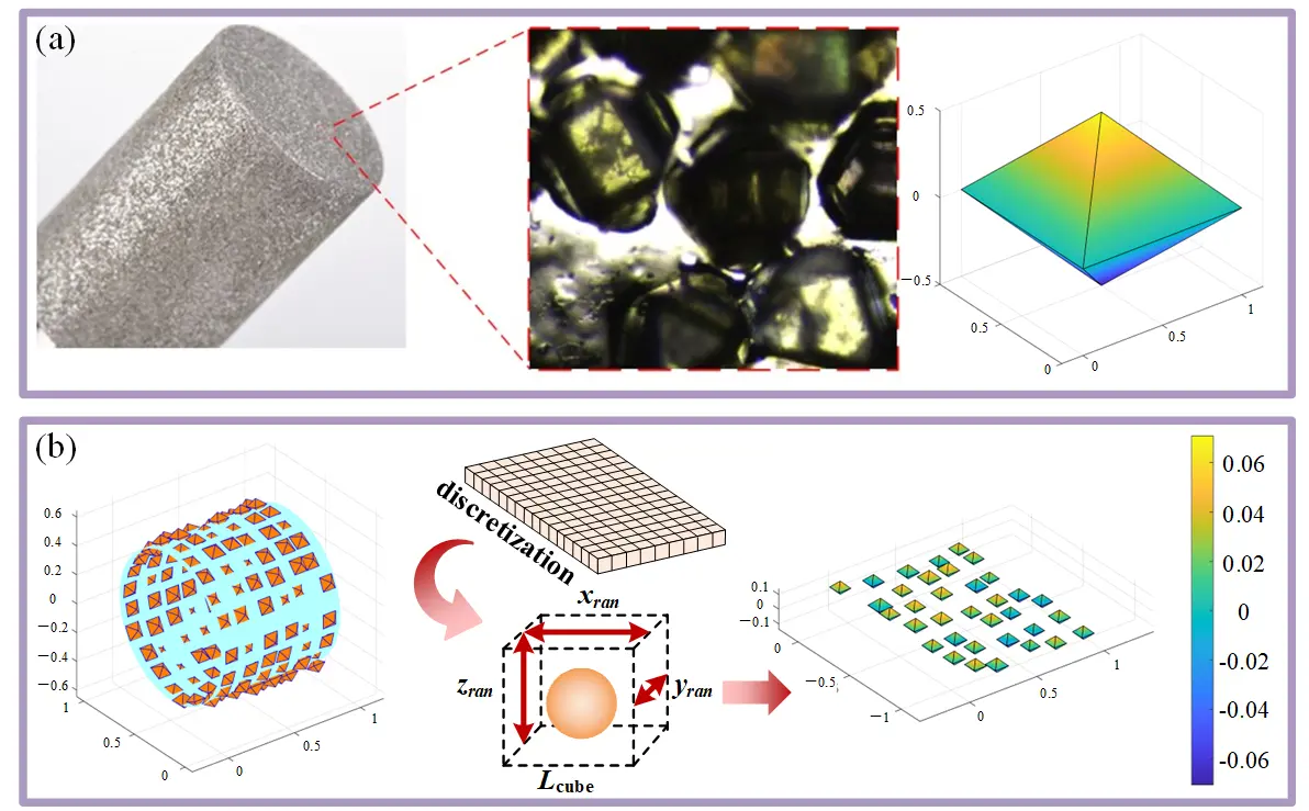
Figure 1. The geometry of abrasive grain (a) single grain morphology (b) abrasive grain distribution simulation.
2.2. Abrasive Kinematics Analysis
Figure 2 shows the movement trajectory of diamond abrasive particles on the surface of a cylindrical grinding head under ultrasonic vibration. The motion trajectory of abrasive grains can be calculated using the following equations:
where R is the average radius of the diamond particle trajectory, w is the angular velocity of the rotation, t is the grinding time in seconds, A the ultrasonic amplitude in micrometers, f is the ultrasonic frequency.
For ultrasonic vibration-assisted grinding with rotation, the abrasive particle movement trajectory is a combination of high-frequency micro-amplitude vibration in the axial direction and circumferential rotation, forming a periodic spatial trajectory.
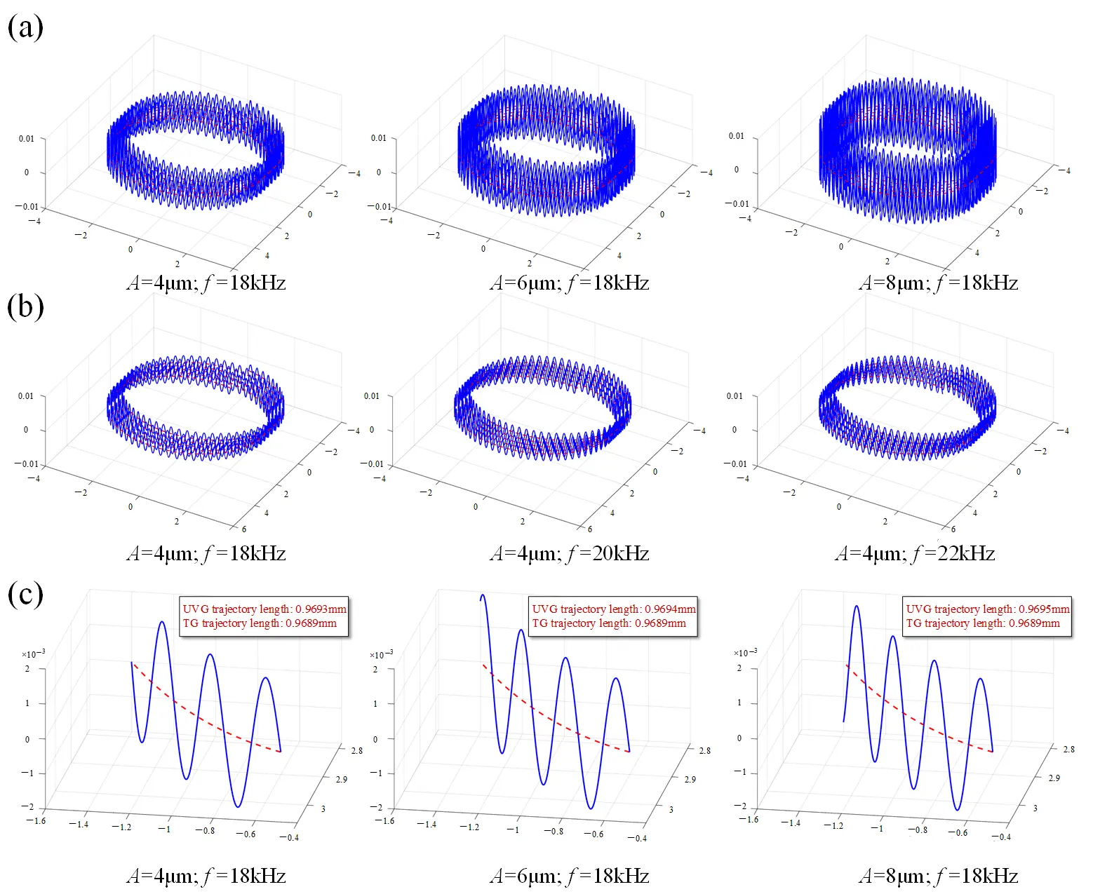
Figure 2. The kinematics of abrasive grain (a) different frequencies (b) different amplitudes (c) local motion maps. The blue line represents UVG, and the red line represents UTG.
2.3. Material Removal Mechanism of Cf/SiC
During the contact between abrasive particles and hard-brittle materials, the material removal behavior shows significant differences with the change in cutting depth. Research has found that this process can be roughly divided into three characteristic stages [36]. Stage 1: Ductile Removal Stage: When the cutting depth of the abrasive particle is small, the material is primarily removed by plastic deformation, similar to the cutting process of metallic materials. During this stage, the processed surface is relatively smooth, with minimal surface cracking. Stage 2: Transition Stage: As the cutting depth increases, plastic deformation becomes less able to release stress fully, and small cracks begin to appear in localized areas. During this stage, the material removal behavior is characterized by a mixture of plastic flow and brittle fracture. Stage 3: Brittle Fracture Dominated Stage: When the cutting depth exceeds the critical value, cracks rapidly propagate, becoming the dominant mechanism. The material is rapidly removed through brittle fragmentation and abrasive particle detachment, resulting in a significant increase in surface roughness.
Understanding the transition between these three stages is crucial for controlling the surface quality of hard-brittle materials and reducing subsurface damage. As shown in Figure 3, the undeformed chip thickness of a single abrasive particle changes from 0 to its maximum value over time. The division of the grinding zone and the corresponding cutting times can be determined by identifying the critical cutting depth [37,38]. When the cutting depth is below the critical value, material removal occurs in the ductile region. When the cutting depth is between the ductile and brittle transition, material removal occurs in the transition zone. When the cutting depth exceeds the critical value, material removal occurs in the brittle region, which can be expressed by the following formula:
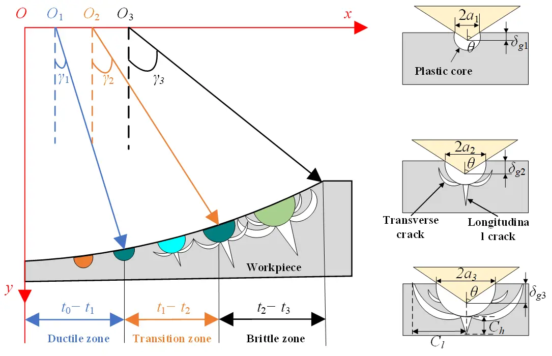
The critical cutting depth between the ductile-brittle transition zone and the brittle region is influenced by the material’s intrinsic properties. The formula for calculating the critical cutting depth of Cf/SiC composites is as follows:
where $$\psi \left(T\right)$$ = 251.1, KID is dynamic fracture toughness, approximately 30% of static fracture toughness. Dynamic fracture toughness is used instead of fracture toughness because ultrasonic vibration softens the material, reducing its surface hardness. Hv is the Vickers hardness. The critical cutting depth between the ductile region and the ductile-brittle transition zone is derived as follows:
where τ is the coefficient for the ductile region, typically set to 0.25. As the cutting time increases, the maximum undeformed chip thickness can be calculated using the following formula:
where ap is the grinding depth, Na is the number of active diamond abrasive particles, η is the ratio of chip width to the average undeformed chip thickness (η = 10), fra is the fraction of diamond particles during grinding (fra = 10), ξ is the volume fraction of diamond tools (ξ = 0.25). For the ductile region, from cutting time t1 to t2, the diamond abrasive particle path is denoted as L1. In the ductile-brittle transition zone, the diamond abrasive particle path is denoted as L2, corresponding to the time range t2 to t3. In the brittle region, the diamond abrasive particle path is denoted as L3, corresponding to the time range t3 to t4. The path length of the diamond abrasive particles and the cutting time can be calculated as follows:
By integrating the speed of the abrasive particl:
3. Ultrasonic Grinding Force Model
3.1. Ductile Removal Stage Force Model
To simplify the modeling of material removal morphology under the complex cutting trajectory of a single abrasive particle, this study adopts a simplification approach where real triangular pyramids (ductile stage) or asymmetric triangular prisms (ductile-brittle and brittle stages) are modeled as equivalent volume triangular prisms. The key to this simplification is that, although the morphologies differ, the volume conservation principle ensures the equivalence of material removal volume [39,40].
Since the cutting depth of a single diamond particle continuously changes over time during the ductile removal stage, it is necessary to determine the average cutting depth. The diamond abrasive particle is considered a rigid octahedron with a stable cutting edge, as shown in Figure 4. In the ductile removal stage, the plastic removal shape of a single diamond abrasive particle on the material surface can be regarded as a triangular pyramid, with the base length being the cutting depth and the height corresponding to the gradual contact arc length in the ductile removal zone. The volume of this triangular pyramid is denoted as Vg1. The calculation formula is as follows:
The cutting behavior of diamond abrasive particles on the workpiece exhibits dynamic characteristics, and the instantaneous cutting depth of the abrasive particle continues to change based on its position on the grinding wheel, the rotation trajectory, and the feed characteristics of the workpiece [41]. If this nonlinear, transient microscopic cutting behavior is directly applied in theoretical modeling, it leads to excessive complexity and difficulty in relating to macro-processing parameters. Therefore, introducing the concept of equivalent average cutting depth can both simplify the transient process into steady-state parameters and integrate the geometric features of abrasive particles, the grinding wheel-workpiece kinematic relationships, and the material’s plastic response, significantly simplifying the grinding force prediction model.
where $${L}_{1-{ave}}$$ is the height of the idealized triangular prism, and $${\delta }_{ga1}$$ is the average cutting depth during the ductile removal stage. The volume of the equivalent idealized triangular prism model remains the same as that of the original triangular pyramid with $${V}_{g1}={V}_{ga1}$$. The average cutting depth is inversely proportional to the height of the idealized triangular prism. Under the premise of not changing the gradually varying contact arc length, i.e., $${L}_{1-{ave}}={L}_{1}$$. $${\delta }_{ga1}$$ is the calculation formula for the average cutting depth in the ductile stage is as follows:
In the ductile removal stage, when the abrasive particle and the workpiece first make contact, the undeformed cutting depth of any abrasive particle is smaller than the critical cutting depth between the ductile region and the ductile-brittle transition region. The material is under elastic deformation, and under the pressure of the abrasive particle, plastic deformation occurs without the formation of cracks. The volume of material removed from the workpiece surface is small. The normal grinding forc is positively correlated with the average cutting depth, the relationship can be expressed as:
Substituting Equation (10) into Equation (11), it can further obtain the average normal cutting force during the ductile removal stage:
The tangential cutting force Ft1 is generated by friction, and it is determined by the friction coefficient μ and the normal cutting force. Its expression is as follows:
The friction coefficient of diamond abrasive particles can be approximated as the ratio of the projected area in the feed direction to the projected area in the tangential direction, and its expression is as follows:
where $${S}_{t1}$$ and $${S}_{n1}$$ are the tangential and normal projected areas of the diamond abrasive particles, respectively. They are expressed as follows:
By combining Equation (13), Equation (14) and Equation (15), the tangential cutting force during the ductile removal stage for a single abrasive particle can be expressed as:
3.2. Ductile-Brittle Transition Removal Stage Force Model
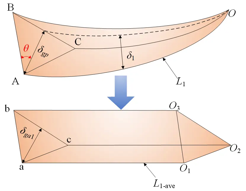
As the abrasive particle’s cutting depth further increases beyond the critical depth of the ductile region and enters the ductile-brittle transition stage, the material removal mechanism undergoes significant changes. At this stage, the pressing action of the abrasive particle not only induces plastic removal but also reveals the formation of transverse and longitudinal cracks. This results in the coexistence of brittle fracture and plastic deformation. As shown in Figure 5, the geometry of the removed material no longer exhibits the stable triangular pyramid shape characteristic of the ductile domain, but evolves into an asymmetric triangular prism structure. The height of the upper and lower triangular faces of the triangular prism is denoted as δgp and δgc, respectively, and the height of the triangular prism is equal to the gradually varying contact arc length during the ductile-brittle transition removal stage. The material removal volume of a single diamond abrasive particle during the ductile-brittle transition removal stage is denoted as:
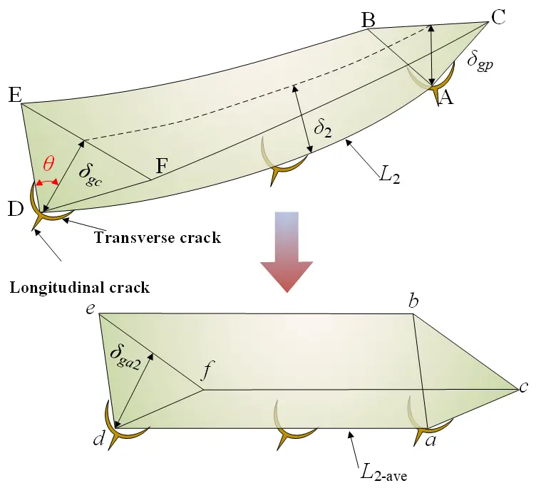
Figure 5. Removal volume and average cutting depth during the ductile brittle transition removal stage.
Figure 5 illustrates the idealization of the asymmetric triangular prism structure into an equivalent triangular prism with equal areas for the top and bottom triangles. The volume of the equivalent model is denoted as:
The volume of the equivalent idealized triangular prism model remains the same as that of the original asymmetric triangular prism structure. The average cutting depth is inversely proportional to the height of the idealized triangular prism. Under the premise of not changing the gradually varying contact arc length, the calculation formula for the average cutting depth during the ductile-brittle transition stage is as follows:
The ductile-brittle transition removal stage is the transitional region from plastic deformation to brittle fracture. In this stage, cracks begin to nucleate and propagate, but plastic deformation still dominates to some extent. The material removal volume in this stage includes contributions from both the plastic deformation zone and the crack propagation zone. The removal volume during the crack nucleation phase is calculated using the following formula:
where Cl, Ch includes transverse cracks and longitudinal cracks. Their lengths are closely related to the material’s fracture toughness, loading stress, elastic modulus, and the initial crack size, as detailed in the formula below:
In the ductile-brittle transition stage, when the crack removal volume equals the average removal volume, the average normal cutting force can be expressed as follows:
The tangential cutting force in the tangential direction for the diamond abrasive particle at this stage is expressed as:
where the compressive yield stress in the contact region is defined as follows:
The projected area can be calculated from the average cutting depth as follows:
By combining Equation (19) and Equation (23), Equation (24), Equation (25), the average tangential cutting force can be expressed as:
3.3. Brittle Removal Stage Force Model
As the cutting depth of the abrasive particle further increases, exceeding the critical value between the ductile-brittle transition zone and the brittle region, transverse and longitudinal cracks become the primary removal mechanism, and the material removal mechanism is dominated by brittle removal. As shown in Figure 6, the shape of the material removal by the abrasive particle remains an asymmetric triangular prism structure, with the areas of the upper and lower triangles being unequal. The height of the triangular prism equals the gradually varying contact arc length during the brittle removal stage. The material removal volume of a single diamond abrasive particle during the brittle removal stage is denoted as:
As shown in Figure 6, the asymmetric triangular prism structure is idealized into an equivalent triangular prism with equal areas for the top and bottom triangles. The volume of the equivalent model is denoted as:
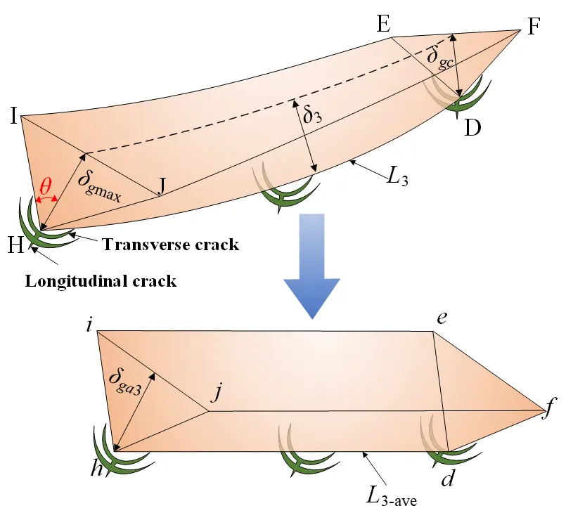
The volume of the equivalent idealized triangular prism model remains the same as that of the original asymmetric triangular prism structure. The average cutting depth is inversely proportional to the height of the idealized triangular prism.
When the material removal process enters the brittle stage, the undeformed cutting depth of any abrasive particle becomes larger than the critical cutting depth between the ductile-brittle transition zone and the brittle region. The material removal mechanism is dominated by the generation and propagation of cracks. In this stage, the load applied by the abrasive particle exceeds the limit value that the material’s fracture toughness can withstand, causing cracks to rapidly propagate and penetrate the material’s removal area, showing typical brittle fracture characteristics. Longitudinal cracks extend in the normal direction, while transverse cracks extend along the surface during the unloading process, ultimately leading to the removal of a large volume of material.
The normal and tangential cutting forces in this stage can be calculated using the following formulas:
where η2 is a dimensionless coefficient related to the material properties, independent of the material’s indentation system.
3.4. Grinding Force Model
Only the abrasive particles that interfere with the workpiece generate grinding force, so calculating the number of effective abrasive particles is crucial for improving the accuracy of the grinding force model. From a macroscopic perspective, the material removal volume rate per rotation period can be considered as a rectangular prism, which can be expressed as:
where ap is the grinding depth, b is the grinding zone width, vw is the feed speed, and n is the spindle speed.
From a microscopic perspective, the material removal volume rate per rotation period can be expressed as:
The theoretical contact number of diamond abrasive particles between the abrasive particles and the workpiece during the grinding process can be calculated using the following formula:
The total normal grinding force is calculated by integrating the normal forces from the ductile removal stage, the ductile-brittle transition removal stage, and the brittle removal stage, and is unified using a correction factor. The expression is as follows:
The pentagonal prism equivalent material removal volume used in this study differs from the actual material removal volume. To compensate for this discrepancy, a constant adjustment coefficient λ is introduced into the force model. This coefficient, experimentally calibrated by Bie et al., is appropriately set to 1.235 [31].
4. Experiment
4.1. Experimental Setup
The experiment was conducted on a setup comprising an ultrasonic spindle and a three-degree-of-freedom moving platform (manufactured by Guangzhou Haozhi Industrial Co., Ltd., Guangzhou, China), as shown in Figure 7.
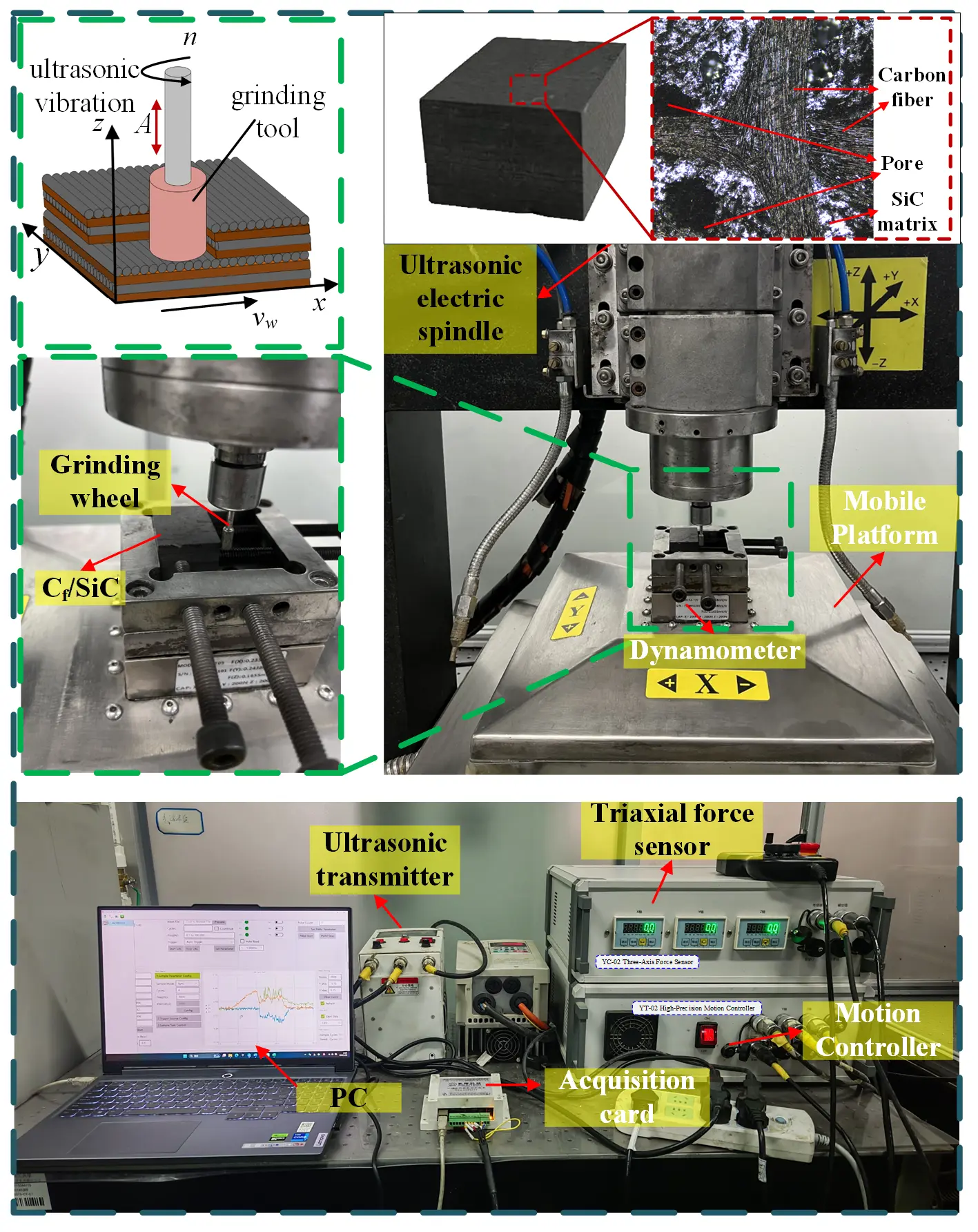
The ultrasonic spindle has a power of 2.5 kW, with a maximum speed of 24,000 r/min. The ultrasonic amplitude A ranges from 2 to 8 µm, and the ultrasonic frequency f ranges from 18 to 22 kHz. The X and Y axes of the three-dimensional moving platform have a speed multiplier in mm by default, with travel ranges limited to 500 mm. The Z-axis speed multiplier is in nm by default, with a travel range limited to 30 mm. The force-sensitive element of the force sensor is fixed above the three-degree-of-freedom moving platform and displays the changes in grinding force during the process via the YDM-III99 three-axis force sensor. The three-axis force sensor is connected to a PC through an A/D data acquisition card for data transmission. The Dyno Ware software is installed on the PC to collect and record the grinding force data during the process, with a sampling frequency of 1 kHz to ensure optimal grinding force information. Considering the material’s hard and brittle characteristics, a 150# cylindrical electroplated diamond grinding head with a diameter of 6 mm is chosen as the tool for this grinding experiment.
4.2. Experimental Materials
Due to the high hardness properties of ceramic materials, a diamond grinding head is used as the tool for this grinding experiment, with a shank diameter of 3 mm and a grinding wheel diameter of 6 mm, using a 150# grit wheel. As shown in Figure 7, the workpiece is a 40 mm × 30 mm × 20 mm piece of 2.5D-Cf/SiC composite material prepared by chemical vapor deposition (CVD). Its mechanical properties are listed in Table 1.
Table 1. Mechanical properties of Cf/SiC composite.
|
Parameter |
Value |
|---|---|
|
Density (g/cm3) |
2.35 |
|
Bending strength (MPa) |
239 |
|
Compressive strength (MPa) |
269 |
|
Tensile strength (MPa) |
125 |
|
Fiber diameter (μm) |
9 |
|
Fiber volume fraction (%) |
46 |
4.3. Experimental Design
To evaluate the influence mechanism of ultrasonic parameters on grinding quality, ultrasonic amplitude and ultrasonic frequency are set as single-factor variables. As shown in Table 2, the single-factor experimental process parameters are as follows:
Group 1, with constant ultrasonic amplitude and identical grinding parameters, varies ultrasonic frequency across four levels: 18,000 Hz, 19,000 Hz, 20,000 Hz, and 21,000 Hz. Each parameter set is tested at least 5 times to eliminate random interference factors. The grinding force signals are continuously collected using a force sensor.
In Group 2, with the ultrasonic frequency and grinding parameters kept constant, the ultrasonic amplitude is varied across four levels: 2 µm, 4 µm, 6 µm, and 8 µm. The subsequent operations are identical to the single-factor experiment on ultrasonic frequency.
Table 2. Single-factor experimental process parameters.
|
Parameter |
Group 1 |
Group 2 |
|---|---|---|
|
Ultrasonic amplitude A (μm) |
5 |
2/4/6/8 |
|
Ultrasonic frequency f (Hz) |
18,000/19,000/20,000/21,000 |
19,000 |
|
Spindle speed n (r/min) |
18,000 |
18,000 |
|
Grinding depth ap (mm) |
0.1 |
0.1 |
|
Feed rate vw (mm/min) |
100 |
100 |
|
Grinding depth b (mm) |
2 |
2 |
5. Model Evaluation
As shown in Figure 8, with fixed grinding parameters and an ultrasonic amplitude of 5 μm, ultrasonic frequency was set to 18 kHz, 19 kHz, 20 kHz, and 21 kHz. The recorded average normal grinding forces were 14.92 N, 13.51 N, 12.82 N, and 11.51 N, while the average tangential grinding forces were 10.75 N, 10.03 N, 8.76 N, and 7.82 N, showing a decreasing trend as the frequency increased. Correspondingly, the theoretical tangential grinding forces and normal grinding forces predicted by the mechanical model were 14.32 N, 13.89 N, 12.95 N, 11.88 N, and 10.02 N, 9.72 N, 9.07 N, 8.32 N, respectively. The trends of the theoretical and actual values were the same, both showing a decrease in grinding forces with increasing ultrasonic frequency. When the ultrasonic frequency was 20 kHz, and the ultrasonic amplitude was 5 μm, the theoretical and actual values of the normal grinding force showed the best similarity, with a matching trend reaching 98.98%. Changes in ultrasonic parameters significantly affect the predictive capability of the grinding force model. This can be primarily attributed to the complexity of the material removal mechanism under ultrasonic vibration, the interference in abrasive motion trajectories, and crack propagation induced by ultrasonic vibration impact.
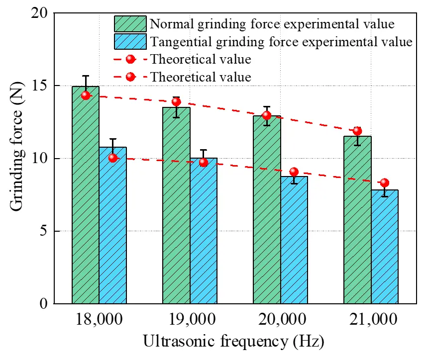
Figure 8. Comparison of experimental and theoretical grinding forces under different ultrasonic frequency parameters.
Ultrasonic frequency determines the length of the vibration cycle during grinding. Increasing the ultrasonic frequency effectively shortens the vibration cycle, increasing the frequency of abrasive particle-workpiece contact within a given time, thereby reducing the cutting depth during each contact. This extends the dominance of the ductile removal phase, suppresses the propagation of brittle cracks, and reduces the normal and tangential loads on the grinding interface. As shown in Figure 9, under fixed grinding parameters and ultrasonic frequency, ultrasonic amplitude was set to 2 μm, 4 μm, 6 μm, and 8 μm. The experimentally measured average normal grinding forces were 15.02 N, 13.52 N, 11.34 N, and 9.80 N, while the tangential grinding forces were 11.27 N, 9.79 N, 8.25 N, and 7.57 N. The experimental results show a gradual decrease in grinding forces with increasing ultrasonic amplitude. Based on the developed mechanical model and numerical simulations, the predicted theoretical tangential and normal grinding forces were 15.45 N, 13.28 N, 11.55 N, 9.91 N, and 10.81 N, 9.30 N, 8.09 N, 6.94 N, respectively. The theoretical values also showed a decreasing trend with increasing ultrasonic amplitude. When the ultrasonic amplitude was 8 μm, and the ultrasonic frequency was 19 kHz, the theoretical and actual values of the normal grinding force showed the best similarity, with a matching value reaching 98.88%.
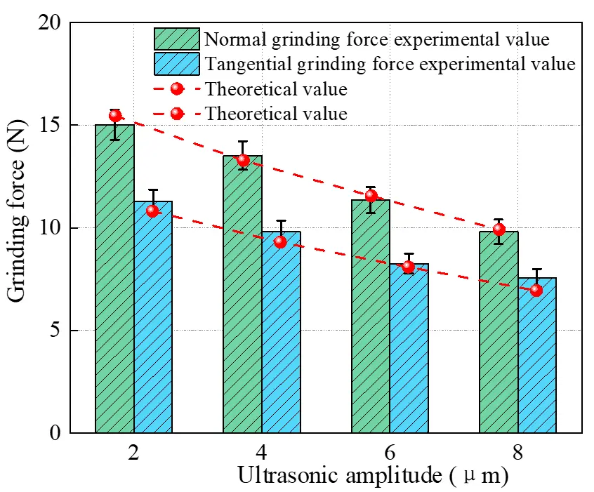
Figure 9. Comparison of experimental and theoretical grinding forces under different ultrasonic amplitude parameters.
The increase in ultrasonic amplitude effectively amplifies the vibration amplitude of the abrasive particles, making the periodic contact/separation of the abrasive particles and workpiece more significant. Larger amplitudes introduce higher energy impacts, which make the material more susceptible to brittle fracture in localized micro-regions. Simultaneously, due to the shorter contact time, the average cutting load per abrasive particle decreases, resulting in reduced normal and tangential grinding forces. Additionally, the micro-episodic effects caused by the increased amplitude also facilitate the timely removal of grinding chips, improving the stress transfer state in the cutting zone. The results of this study not only reveal the control mechanisms of ultrasonic amplitude on grinding force but also further demonstrate that reasonable control of ultrasonic amplitude can contribute to low-damage grinding of Cf/SiC materials.
6. Conclusions
Over the past decade, the high-efficiency and precision manufacturing technology and theory of fiber-reinforced silicon carbide ceramic matrix composites have been a hot topic in both academia and industry and a widely recognized technical challenge. Ultrasonic vibration-assisted grinding, as an effective process for improving surface quality, has been extensively studied. However, to advance the theoretical understanding of grinding forces, this paper establishes a grinding force model based on the equivalent principle of material removal rate at each stage, with the following conclusions:
-
Ultrasonic vibration-assisted grinding experiments were conducted to validate the prediction model. When ultrasonic frequency was the single variable, with an ultrasonic frequency set to 20 kHz and an ultrasonic amplitude of 5 μm, the theoretical and actual values of normal grinding force showed the best similarity, with a matching trend reaching 98.98%. When ultrasonic amplitude was the single variable, with an ultrasonic amplitude of 5 μm and ultrasonic frequency set to 19 kHz, the theoretical and actual values of normal grinding force showed the best similarity, with a matching trend reaching 98.88%.
-
Under unchanged grinding parameters, when the ultrasonic frequency was increased from 18 kHz to 21 kHz, the normal grinding force decreased from 14.92 N to 11.51 N (a reduction of 22.8%), and the tangential grinding force decreased from 10.75 N to 7.82 N (a reduction of 27.3%). When the ultrasonic frequency was fixed, as the amplitude increased from 2 μm to 8 μm, normal grinding force decreased from 15.02 N to 9.80 N (a reduction of 34.8%), and tangential force decreased from 11.27 N to 7.25 N (a reduction of 35.7%).This indicates that ultrasonic parameters can influence grinding forces, thereby potentially affecting grinding quality.
However, a detailed modeling process should begin with the fundamental mechanical analysis of the interaction between a single abrasive grain and the workpiece, and then be extended to encompass the entire grinding behavior. Therefore, the mechanical interaction between a single abrasive grain and the workpiece warrants further investigation, accounting for factors such as fiber orientation, size effects, strain rate effects, and material properties. Furthermore, developing a global dynamic grinding force model that accounts for both workpiece material characteristics and the geometric distribution of abrasive grains on the grinding wheel represents a key research focus and a significant challenge.
Statement of the Use of Generative AI and AI-Assisted Technologies in the Writing Process
During the preparation of this manuscript, the author(s) used [Deepseek/DeepSeek Artificial Intelligence Basic Technology Research Co., Ltd., Hangzhou in order to [polish language]. After using this tool/service, the authors reviewed and edited the content as needed and take full responsibility for the content of the published article.
Author Contributions
Conceptualization, A.C. and R.S.; Methodology, A.C.; Software, R.S.; Validation, Y.S., N.L. and W.X.; Formal Analysis, X.Z.; Investigation, A.C.; Resources, G.L.; Data Curation, A.C., H.W. and C.J.; Writing—Original Draft Preparation, W.X.; Writing—Review & Editing, W.X.
Ethics Statement
Not applicable.
Informed Consent Statement
Not applicable.
Data Availability Statement
Not applicable.
Funding
This research received no external funding.
Declaration of Competing Interest
The authors declare that they have no known competing financial interests or personal relationships that could have appeared to influence the work reported in this paper.
References
-
Xu WH, Gao T, Liu DW, Xu PM, An QL, Wang YQ, et al. Progress in grinding mechanical modeling of fiber reinforced SiC ceramic matrix composites. Acta Mater. Compos. Sin. 2024, 41, 4628–4653. DOI:10.13801/j.cnki.fhclxb.20240923.001 [Google Scholar]
-
Wang XB, Wu MQ, Song CS, Zhao B. Experimental and mechanism study of Cf/SiC undergoing longitudinal-torsional ultrasonic vibration-assisted grinding. Int. J. Adv. Manuf. Technol. 2023, 127, 5791–5802. DOI:10.1007/s00170-023-11982-1 [Google Scholar]
-
Cao XY, Lin B, Zhang XF. Investigations on grinding process of woven ceramic matrix composite based on reinforced fiber orientations. Compos. Part B-Eng. 2015, 71, 184–192. DOI:10.1016/j.compositesb.2014.11.029 [Google Scholar]
-
Chen GJ, Xu JK, Wang JD, Li Y, Wang JQ, Yu ZJ, et al. Numerical and experimental study on the amplitude effect of ultrasonic vibration-assisted milling of 3D needle-punched Cf/SiC composite. Ceram. Int. 2022, 48, 17893–17914. DOI:10.1016/j.ceramint.2022.03.061 [Google Scholar]
-
Qiao GC, Cheng Z, Zheng W, Yi SC, Zhang FJ. Grinding force model for longitudinal-torsional ultrasonic-assisted face grinding of ceramic matrix composites. Int. J. Adv. Manuf. Technol. 2022, 120, 7721–7733. DOI:10.1007/s00170-022-09174-4 [Google Scholar]
-
Yao LX, Liu ZQ, Song QH, Wang B, Cai YK. Prediction modelling of cutting force in rotary ultrasonic end grinding 2.5D woven SiO2f/SiO2 ceramic matrix composite. Compos. Struct. 2023, 304, 16. DOI:10.1016/j.compstruct.2022.116448 [Google Scholar]
-
Huang B, Wang WH, Xiong YF, Wu XF, Liu JT, Liu C, et al. Investigation of force modeling in ultrasonic vibration-assisted drilling SiCf/SiC ceramic matrix composites. J. Manuf. Process 2023, 96, 21–30. DOI:10.1016/j.jmapro.2023.04.040 [Google Scholar]
-
Zhang MH, Shan CW, Xia ZW, Luo M, Zhang DH. Scratch-induced surface formation mechanism in C/SiC composites. Int. J. Mech. Sci. 2024, 265, 24. DOI:10.1016/j.ijmecsci.2023.108885 [Google Scholar]
-
Qu SS, Gong YD, Yang YY, Wen XL, Yin GQ. Grinding characteristics and removal mechanisms of unidirectional carbon fibre reinforced silicon carbide ceramic matrix composites. Ceram. Int. 2019, 45, 3059–3071. DOI:10.1016/j.ceramint.2018.10.178 [Google Scholar]
-
Qu SS, Gong YD, Yang YY, Sun Y, Wen XL, Qi Y. Investigating Minimum Quantity Lubrication in Unidirectional Cf/SiC composite grinding. Ceram. Int. 2020, 46, 3582–3591. DOI:10.1016/j.ceramint.2019.10.076 [Google Scholar]
-
Wang ZW, Dong ZG, Ran YC, Kang RK, Bao Y. On understanding the mechanical properties and damage behavior of Cf/SiC composites by indentation method. J. Mater. Res. Technol.-JMRT 2023, 26, 3784–3802. DOI:10.1016/j.jmrt.2023.08.117 [Google Scholar]
-
Liu Y, Quan Y, Wu CJ, Ye LZ, Zhu XJ. Single diamond scribing of SiCf/SiC composite: Force and material removal mechanism study. Ceram. Int. 2021, 47, 27702–27709. DOI:10.1016/j.ceramint.2021.06.195 [Google Scholar]
-
Xiong YF, Liu C, Wang WH, Jiang RS, Huang B, Wang DH, et al. Assessment of machined surface for SiCf/SiC ceramic matrix composite during ultrasonic vibration-assisted milling-grinding. Ceram. Int. 2023, 49, 5345–5356. DOI:10.1016/j.ceramint.2022.10.058 [Google Scholar]
-
Islam S, Yuan SM, Li Z. Mathematical modeling and experimental studies on axial drilling load for rotary ultrasonic drilling of C/SiC composites. Int. J. Adv. Manuf. Technol. 2020, 107, 1309–1326. DOI:10.1007/s00170-020-05052-z [Google Scholar]
-
Zhang LF, Ren CZ, Ji CH, Wang ZQ, Chen G. Effect of fiber orientations on surface grinding process of unidirectional C/SiC composites. Appl. Surf. Sci. 2016, 366, 424–431. DOI:10.1016/j.apsusc.2016.01.142 [Google Scholar]
-
Dong ZG, Zhang HT, Kang RK, Ran YC, Bao Y. Mechanical modeling of ultrasonic vibration helical grinding of SiCf/SiC composites. Int. J. Mech. Sci. 2022, 234, 16. DOI:10.1016/j.ijmecsci.2022.107701 [Google Scholar]
-
Wang W, Zhou Z, Wang Q, Gao B, Mao C. Muti-Energy Field-Assisted Grinding of Hard and Brittle Materials: Tools, Equipment and Mechanisms. Intell. Sustain. Manuf. 2025, 2, 10022. DOI:10.70322/ism.2025.10022 [Google Scholar]
-
Liu C, Zhang Y, Zhu L, Li Q, Shu X, Qin S, et al. A Review of Ultrasonic Vibration-Assisted Grinding for Advanced Materials. Intell. Sustain. Manuf. 2025, 2, 10001. DOI:10.70322/ism.2025.10001 [Google Scholar]
-
Ding K, Fu YC, Su HH, Chen Y, Yu XZ, Ding GZ. Experimental studies on drilling tool load and machining quality of C/SiC composites in rotary ultrasonic machining. J. Mater. Process Technol. 2014, 214, 2900–2907. DOI:10.1016/j.jmatprotec.2014.06.015 [Google Scholar]
-
Zhou YG, Tian CC, Jia SQ, Ma LJ, Yin GQ, Gong YD. Study on Grinding Force of Two-Dimensional Ultrasonic Vibration Grinding 2.5D-C/SiC Composite Material. Crystals 2023, 13, 20. DOI:10.3390/cryst13010151 [Google Scholar]
-
Gao T, Liu JX, Sun XF, Zhang YB, Yang M, Liu MZ, et al. Damage mechanism and evaluation of ultrasonic vibration nanolubricant grinding CFRP composites. Polym. Compos. 2025, 46, 11447–11463. DOI:10.1002/pc.29696 [Google Scholar]
-
Gao T, Xu PM, Wang W, Zhang YB, Xu WH, Wang YQ, et al. Force model of ultrasonic empowered minimum quantity lubrication grinding CFRP. Int. J. Mech. Sci. 2024, 280, 27. DOI:10.1016/j.ijmecsci.2024.109522 [Google Scholar]
-
Chen J, An QL, Ming WW, Chen M. Investigation on machined surface quality in ultrasonic-assisted grinding of Cf/SiC composites based on fracture mechanism of carbon fibers. Int. J. Adv. Manuf. Technol. 2020, 109, 1583–1599. DOI:10.1007/s00170-020-05739-3 [Google Scholar]
-
Dong ZG, Ding K, Cai XT, Zhang QH, Bao Y, Kang RK, et al. Effects of laser and ultrasonic combined action on material removal of Cf/ SiC composites during single grain scratching. J. Manuf. Process 2025, 151, 843–857. DOI:10.1016/j.jmapro.2025.07.058 [Google Scholar]
-
Cao SY, Li HN, Huang WJ, Zhou Q, Lei T, Wu CQ. A delamination prediction model in ultrasonic vibration assisted drilling of CFRP composites. J. Mater. Process Technol. 2022, 302, 17. DOI:10.1016/j.jmatprotec.2021.117480 [Google Scholar]
-
Qu SS, Yao P, Gong YD, Yang YY, Chu DK, Zhu QS. Modelling and grinding characteristics of unidirectional C-SiCs. Ceram. Int. 2022, 48, 8314–8324. DOI:10.1016/j.ceramint.2021.12.036 [Google Scholar]
-
Kong X, Li C, Li Z, Yang M, Cui X, Liu M, et al. Biological bone and replacement materials in grinding: force model and processing capability. Intell. Sustain. Manuf. 2025, 2, 10003. DOI:10.70322/ism.2025.10003 [Google Scholar]
-
Wei JH, Wang HJ, Lin B, Sui TY, Zhao FF, Fang S. A force model in single grain grinding of long fiber reinforced woven composite. Int. J. Adv. Manuf. Technol. 2019, 100, 541–552. DOI:10.1007/s00170-018-2719-x [Google Scholar]
-
Xu WH, Li CH, Xu PM, Wang W, Zhang YB, Yang M, et al. Grinding mechanics of ceramics: From mechanism to modeling. Adv. Manuf. 2025, 14, 4–42. DOI:10.1007/s40436-025-00553-0 [Google Scholar]
-
Zhang MH, Shan CW, Xia ZW, Jia FC, Luo M. Dynamic mechanical model in grinding C/SiC composites. Int. J. Mech. Sci. 2024, 268, 28. DOI:10.1016/j.ijmecsci.2024.109042 [Google Scholar]
-
Bie WB, Chen F, Wang XB, Chen SP, Fu ZX, Zhao B. Longitudinal-torsional coupled rotary ultrasonic machining end surface grinding of SiCf/SiC composites: A mechanical model of cutting force. Int. J. Adv. Manuf. Technol. 2023, 129, 1227–1248. DOI:10.1007/s00170-023-12360-7 [Google Scholar]
-
Wang YG, Wang HJ, Wei JH, Li B, Xu JY, Fang S. Finite element analysis of grinding process of long fiber reinforced ceramic matrix woven composites: Modeling, experimental verification and material removal mechanism. Ceram. Int. 2019, 45, 15920–15927. DOI:10.1016/j.ceramint.2019.05.100 [Google Scholar]
-
Liu Q, Huang GQ, Xu XP, Fang CF, Cui CC. Influence of grinding fiber angles on grinding of the 2D-Cf/C-SiC composites. Ceram. Int. 2018, 44, 12774–12782. DOI:10.1016/j.ceramint.2018.04.083 [Google Scholar]
-
Dong ZG, Zhang HT, Bao Y, Yang F, Wang ZW, Kang RK. Material Removal Behavior of Ultrasonic Vibration Helical Grinding of SiCf/SiC Composites. J. Manuf. Sci. Eng.-Trans. ASME 2023, 145, 15. DOI:10.1115/1.4056595 [Google Scholar]
-
Ran YC, Kang RK, Dong ZG, Jin ZJ, Bao Y. Ultrasonic assisted grinding force model considering anisotropy of SiCf/SiC composites. Int. J. Mech. Sci. 2023, 250, 15. DOI:10.1016/j.ijmecsci.2023.108311 [Google Scholar]
-
Qu SS, Gong YD, Yang YY, Xu YC, Wang WW, Xin B, et al. Mechanical model and removal mechanism of unidirectional carbon fibre-reinforced ceramic composites. Int. J. Mech. Sci. 2020, 173, 11. DOI:10.1016/j.ijmecsci.2020.105465 [Google Scholar]
-
Luna GG, Axinte D, Novovic D. Engineered grinding tools reimplemented by precise sharpening: A case study on an ultrahard ceramic matrix composite (CMC). CIRP Ann.-Manuf. Technol. 2022, 71, 289–292. DOI:10.1016/j.cirp.2022.04.011 [Google Scholar]
-
Cao C, Song QH, Fu H, Ji HS, Liu ZQ, Jiang LP. Fiber orientation effects on grinding characteristics and removal mechanism of 2.5D Cf/SiC composites. Chin. J. Aeronaut. 2023, 36, 425–441. DOI:10.1016/j.cja.2023.02.023 [Google Scholar]
-
Zhang MH, Xia ZW, Shan CW, Luo M. Analytical model of grinding force for ultrasonic-assisted grinding of Cf/SiC composites. Int. J. Adv. Manuf. Technol. 2023, 126, 2037–2052. DOI:10.1007/s00170-023-11257-9 [Google Scholar]
-
Azarhoushang B, Tawakoli T. Development of a novel ultrasonic unit for grinding of ceramic matrix composites. Int. J. Adv. Manuf. Technol. 2011, 57, 945–955. DOI:10.1007/s00170-011-3347-x [Google Scholar]
-
Zhang ZK, Yuan SM, Gao XX, Xu WW, Zhang JQ, An WZ. Analytical modelling of side grinding of orthogonal laminated SiCf/SiC composites based on effective elastic properties. Int. J. Adv. Manuf. Technol. 2022, 120, 6419–6434. DOI:10.1007/s00170-022-09170-8 [Google Scholar]