Alkaline Leaching Lithium from Spent Carbon Anode and Coupling of Extraction-Carbonization for Cryolite Regeneration

Alkaline Leaching Lithium from Spent Carbon Anode and Coupling of Extraction-Carbonization for Cryolite Regeneration
Yonghong Qin 1,2,* Xiaodi Niu 1,2 Xianglin Li 1,2 Yujiao Liu 1,2 Jianming Gao 1,2 Zihe Pan 1,2 Da Li 1,2,*
Received: 11 December 2025 Revised: 19 January 2026 Accepted: 26 January 2026 Published: 02 February 2026

© 2026 The authors. This is an open access article under the Creative Commons Attribution 4.0 International License (https://creativecommons.org/licenses/by/4.0/).
1. Introduction
Lithium is hailed as the most strategically significant green energy metal of the 21st century. Lithium and its compounds possess various excellent physicochemical properties, thus being widely used [1]. Currently, issues surrounding resource security, energy consumption, and environmental protection are growing increasingly prominent worldwide, which has driven a steady rise in demand for renewable energy. The global shift towards a low-carbon future has intensified demand for key energy elements [2,3]. The development and utilization of lithium resources have garnered widespread attention and in-depth research globally [4]. In electrolytic aluminum production, large amounts of medium and low-grade bauxite (with Li2O content ranging from 0.1% to 0.5%) are used to meet the growing demand for aluminum products. The cryolite alumina molten salt electrolysis method proposed by Hall and Héroult has always been the mainstream process in the aluminum electrolysis industry [5,6]. Fluoride salt additives (e.g., LiF) are employed to optimize the molecular ratio of electrolyte and reduce its liquidus temperature in this production process [7], thereby ensuring stable electrolysis operation.
Lithium containing bauxite is continuously fed into the electrolysis system. As electrolysis proceeds, lithium gradually accumulates in SCA, existing as lithium fluoride, lithium oxide, or other compounds. The lithium content in SCA can reach approximately 1.5%, which has exceeded the grade in the lithium containing ore [8]. These carbon residues are typically disposed of by stacking or landfilling. This practice not only takes up valuable space in electrolytic aluminum enterprises but also poses a serious threat to human health and the ecological environment, given the high fluoride content in the slag. Therefore, the harmless and resourceful treatment of SCA has become an urgent issue to address for the electrolytic aluminum industry. Currently, in addition to recycling carbon and electrolytes, extracting lithium from lithium-containing SCA is a viable and eco-friendly approach to treating such slag [9,10]. It not only prevents resource waste and environmental pollution but also eases the strain of lithium resource scarcity.
In recent years, research on lithium extraction from lithium-containing SCA has been increasing in number [10,11,12,13,14]. Yang [15] proposes a green, efficient method for lithium recovery from Li-containing waste aluminum electrolytes, where CaCl2 calcination is coupled with deionized water leaching for lithium recovery from the waste electrolytes. This entire technical route uses no strong acids or bases. One-step roasting and one-step leaching enable efficient recovery of high-purity Li2CO3 (an energy-storage material) from the waste electrolytes, with lithium recovery exceeding 98% and Li2CO3 purity remaining above 99.0%. Tian et al. [16] employed an ultrasound-assisted alkaline leaching process using NaOH to treat waste cathode carbon. Under optimal conditions, they achieved high leaching efficiencies of 89.17% for fluoride and 86.33% for lithium ions. The key advantage of this method is the significant reduction in leaching time to 50 min compared to conventional methods; however, it involves high alkali consumption and energy input for ultrasonication. Dong et al. [17] developed a calcium sulfate (CaSO4) roasting followed by water leaching technique to process overhaul slag. Their process successfully achieved lithium extraction and fluorine fixation rates both exceeding 99.7%. The main advantages are the high selectivity for lithium and the stabilization of fluoride as an inert form; notable disadvantages include the high roasting temperature required and the potential risk of SO2 gas emissions. Liu et al. [18] proposed a causticization strategy using Ca(OH)2 for the treatment of electrolytic aluminum slag (EAS). This method enabled selective lithium recovery with 99.06% efficiency while effectively fixing impurities, resulting in very low co-leaching of aluminum, silicon, and fluoride (<1.14%). The process is advantageous for avoiding strong acids and for environmental safety, though it generates a solid residue that requires safe disposal. Wu proposed a new process for separating and recovering lithium from lithium-containing aluminum electrolytes using a roasting-leaching process [19]. The maximum lithium leaching rate reached 73.1%, enabling efficient lithium leaching from lithium-containing aluminum electrolytes. The leaching solution was neutralized and purified to recover lithium in the form of Li2O3, while the leaching residue could be reused as a raw material for aluminum electrolysis cells.
In recent years, studies have also investigated aluminum salts as leaching agents for extracting lithium from SCA. Cui et al. proposed a method for recovering lithium from SCA with aluminum chloride as the leaching agent [20]. Under a leaching temperature of 95 °C, a liquid-solid ratio of 3, a pH of 0.5, and an AlCl3 concentration of 0.85 mol/L, the lithium leaching rate reaches 88.3%. The addition of AlCl3 is crucial for disrupting the cryolite structure, ultimately leading to the cleavage of Al-F bonds and the release of Li+ into the leachate. Northeastern University has developed a process to extract lithium from lithium-containing waste aluminum electrolytes [21]. The process mainly consists of three stages: HNO3-Al(NO3)3 leaching, leachate neutralization, and lithium carbonate precipitation. The lithium leaching rate reaches approximately 88.0%. The dissolved lithium in the solution precipitates as Li2CO3 for separation, with the resulting Li2CO3 achieving a purity of 98.8%.
Both the acidification method and the acidification roasting method can break the mineral phase structure of cryolite. These methods can realize large-scale leaching of components, converting them into soluble salts and significantly improving metal extraction rates. Additionally, by adjusting the type and concentration of acid, the method exhibits strong adaptability for processing various components of carbon slag [22,23]. However, their processes are relatively long with high energy consumption—particularly when handling SCA with high alkalinity or high alumina content [24,25,26,27]. They involve high acid consumption, and treating the waste liquid generated after acid leaching is complex. Additionally, the subsequent pH adjustment process requires large quantities of alkaline reagents, which increases process complexity and is unfavorable for subsequent production. Alkaline leaching of SCA offers advantages such as mild reaction conditions and minimal corrosion of equipment. Furthermore, toxic fluorides and cyanides are less likely to volatilize or escape in alkaline environments [28,29]. The alkaline leaching process avoids the large volumes of toxic hydrogen fluoride gas produced by acid leaching, enabling complete quantitative recovery of valuable components in SCA. Moreover, combining the alkaline leaching process with carbonization can further facilitate the preparation of cryolite and sodium carbonate [30,31]. This integrated process boasts technical merits, including low energy consumption and high product yield.
The HBTA-TOPO synergistic extraction system is composed of N-benzoyl-N-phenylhydroxylamine (HBTA) as the extractant and tri-n-octylphosphine oxide (TOPO) as the synergist. HBTA exhibits strong chelating ability with Li+ due to its specific functional groups, while TOPO can enhance the solubility of the HBTA-Li complex in the organic phase, thereby improving extraction efficiency and selectivity. This system has previously been applied to lithium extraction from high-alumina fly ash and alkaline brines [32,33]. Xing et al. [32] achieved selective lithium recovery from high-alumina fly ash leachate (in an alkaline environment, pH 10–12) using this system, with a lithium extraction rate of over 85% and negligible co-extraction of Al and Fe. Zhang et al. [33] verified its stability in alkaline brines, where it maintained high lithium selectivity even in the presence of high-concentration Na+. To adapt this system to the SCA alkaline leaching solution (pH ≈ 13, high Na+/Al3+ ratio, and coexisting F− ions), this study optimizes the system from two aspects: (1) Adjusting the volume ratio of HBTA to TOPO (optimized to 3:1) to strengthen the chelation of Li+ while inhibiting the coordination of Al3+ and F− with HBTA; (2) Optimizing the organic-aqueous phase ratio and extraction time to match the ion composition of the SCA leachate, avoiding emulsion formation caused by high alkalinity. The core innovation lies in integrating the modified HBTA-TOPO system with the alkaline leaching process, enabling a closed-loop alkaline leaching-alkaline extraction operation without pH adjustment and overcoming the defects of traditional acid extraction (high reagent consumption, secondary waste generation). The unique advantages of this system in alkaline systems are prominent: first, it maintains stable extraction performance under strong alkaline conditions, avoiding hydrolysis or decomposition of extractants that occurs in acidic extraction systems; second, it exhibits excellent selectivity for Li+ over Na+, Al3+, and F− in alkaline media, solving the problem of low lithium separation efficiency caused by ion interference; third, it has good compatibility with the subsequent carbonation process, as the extraction raffinate (rich in Na+, Al3+, and F−) can be directly reused for cryolite synthesis without additional purification.
This study focuses on the efficient leaching and enrichment of lithium from SCA under alkaline conditions, as well as the high-value technology for cryolite preparation via waste liquid reuse. Systematic investigations are conducted on the leaching efficiency and migration behavior of Li+ to optimize the alkaline leaching process of SCA [8]. Characterization and analysis of the transformation mechanism of the mineral phase structure of SCA before and after leaching are performed using techniques such as XRD, SEM, FT-IR, and XPS. Given the difficulty in separating and recovering Li+ from alkaline leaching solutions, characterized by the coexistence of high-concentration Na+, Al3+, and F− as well as strong alkalinity that compromises selective extraction, a high-efficiency approach for lithium extraction from such alkaline media using the HBTA-TOPO synergistic extraction system is proposed [32,33]. Subsequently, the residual solution is utilized to study the carbonation synthesis of cryolite, and the optimal conditions for cryolite carbonation synthesis are determined. The obtained cryolite products are subjected to characterization and analysis. This study holds important guiding significance for the clean utilization of solid waste and the high-value recovery of valuable metals in electrolytic aluminum enterprises.
2. Experimental Materials and Methods
2.1. Materials
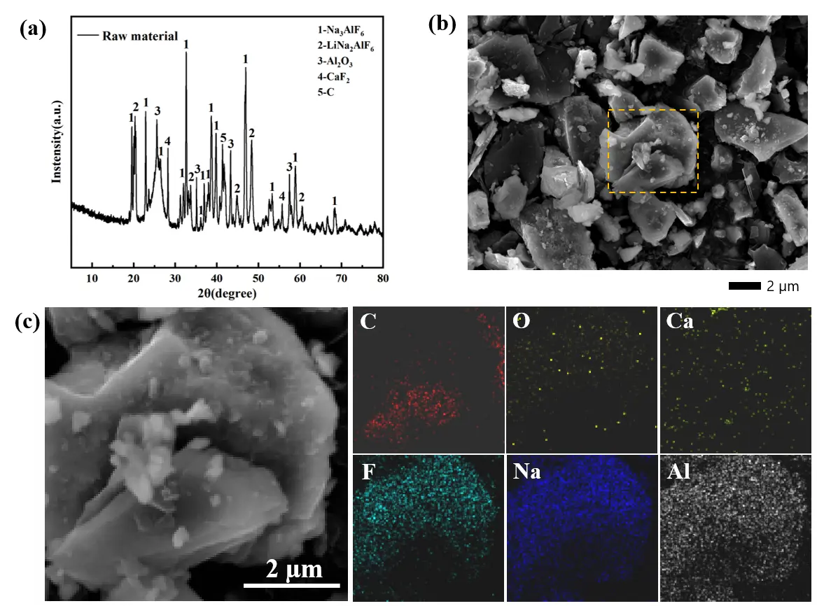
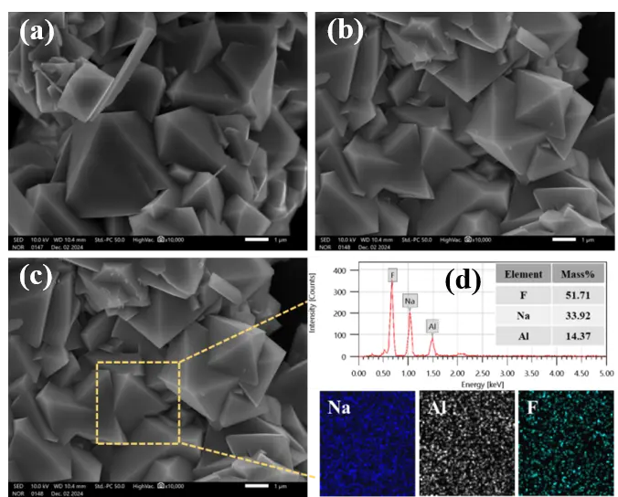
The SCA employed in this study was sourced from an electrolytic aluminum plant in Xing County, Shanxi Province. Prior to leaching, the bulk electrolytic aluminum slag was crushed, ground, sieved, and dried to prepare a powder sample with a particle size of 180 mesh. To gain deeper insights into the SCA’s physicochemical properties, its main phase composition, elemental content, and microscopic morphology were characterized via XRD, ICP-OES, XRF, and SEM-EDS, with the results presented in Figure 1. Specifically, the XRD pattern of raw SCA (Figure 1a) reveals its main phases: cryolite (Na3AlF6), lithium cryolite (Na2LiAlF6), alumina (Al2O3), calcium fluoride (CaF2), and carbon (b). The SEM image of raw SCA (Figure 1b) shows a dense, irregular, blocky morphology, with fine granular particles adhering to the carbon matrix surface. The mapping results (Figure 1c) further confirm the uniform distribution of Na, Al, F, and Li elements on the SCA surface. This morphological and elemental distribution characteristic indicates that the lithium-bearing phases are closely combined with the carbon matrix and electrolyte components in the SCA, laying a foundation for the subsequent alkaline leaching process to destroy the mineral structure and release Li+. ICP-OES was used to quantify the contents of Li, Al, Na, and Ca in the raw SCA, while XRF conducted semi-quantitative analysis of fluorine (F) and carbon (C). As shown in Table 1, the SCA’s main elemental contents are: F (43.89%), Na (25.4%), Al (15.5%), C (7.99%), Ca (1.34%), and Li (1.43%).
Table 1. Elemental content analysis.
|
Component |
Li |
Na |
Al |
Ca |
F |
C |
Other |
|---|---|---|---|---|---|---|---|
|
Content (wt%) |
1.43 |
25.4 |
15.5 |
1.34 |
43.89 |
7.99 |
4.45 |
2.2. Experimental Procedure
2.2.1. Process Flow Diagram
In this paper, a NaOH solution was used to efficiently leach lithium from SCA and to restore cryolite. Firstly, the lithium-containing filtrate and slag are obtained by NaOH leaching. The lithium-containing filtrate is extracted to obtain a lithium-rich solution, and the extracted and washed solutions are reacted to produce cryolite products after adjusting the pH with CO2. Figure 2 shows the specific process flow diagram.
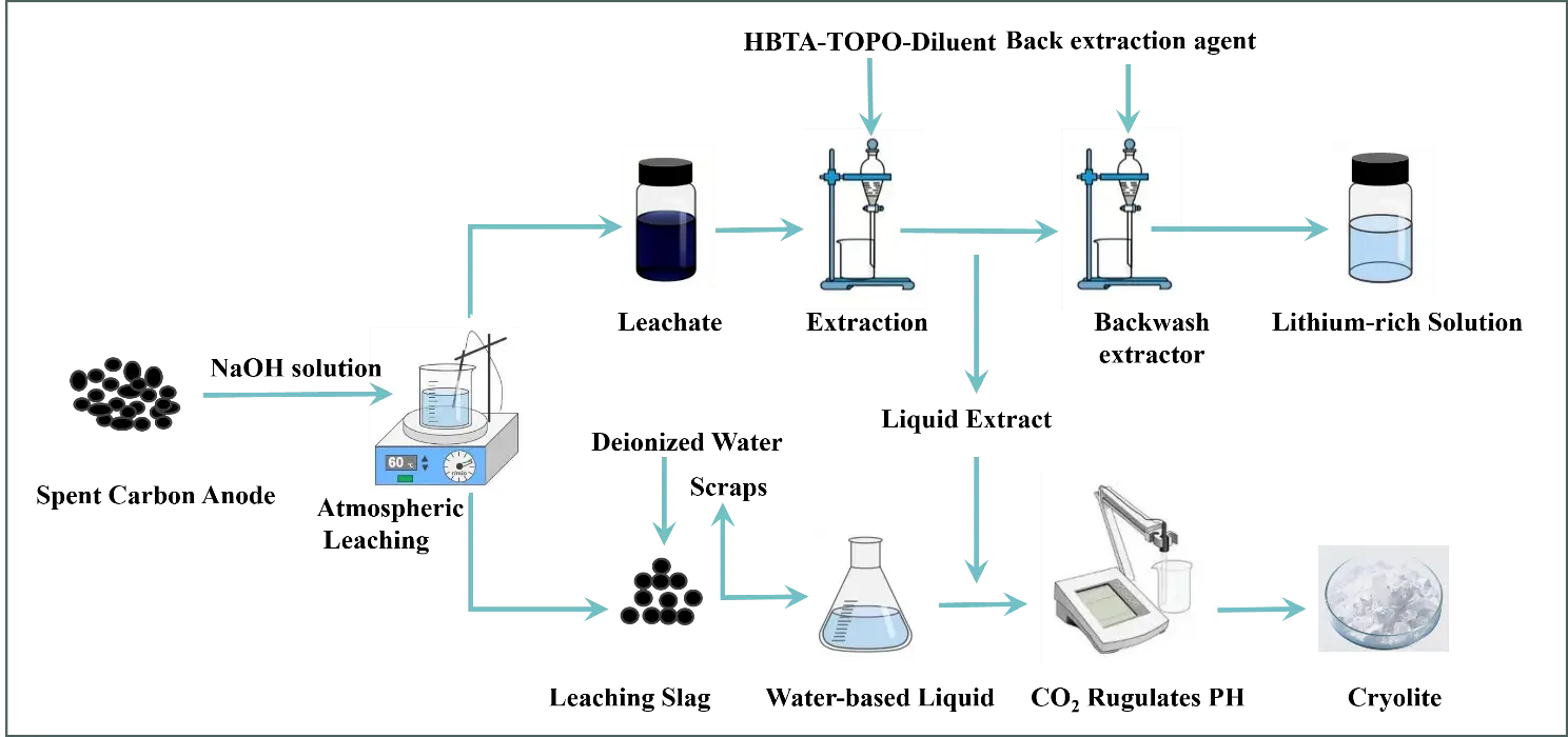
Figure 2. Process flow of lithium extraction by leaching of SCA from electrolytic aluminum and remediation of cryolite.
2.2.2. NaOH Leaching Experiment
The leaching experiment was carried out in a collector-type thermostatically heated magnetic stirrer equipped with a temperature control system. First, NaOH solution and 50 g SCA were transferred to a three-necked flask. Meanwhile, the mixture was stirred and reacted for 2 h. After the reaction, the solid-liquid separation was achieved by filtration using a Brinell funnel. The filtrate was washed three times with 300 mL of hot water, and the concentrations of Li+, Ca2+, Al3+, and Na+ in the leachate and washing solution were analyzed by ICP-OES. The leaching residue was dried and ground for subsequent analysis of physical phase composition and microstructure. The leaching rate of each element was calculated as the ratio of the total mass of the element in the leaching solution and washing solution to the initial mass of the element in the raw anode carbon slag, as shown in Equation (1):
where E is the leaching rate (%), Ci is the content of target element i in leachate (mg/L), Vi is the volume of leachate (L), mi is the mass of raw material (g), and Wi is the weight percentage of target element i in raw material (%).
2.2.3. Extraction Experiment
Synergistic extractant systems with varying HBTA, TOPO, and kerosene ratios were prepared. For extraction, 10 mL of leachate was mixed with 10 mL of the HBTA + TOPO + kerosene mixture (at specified ratios), resulting in a 1:1 organic-to-aqueous phase volume ratio, and the extraction was repeated three times. The kerosene used in the extraction experiment was conventional industrial kerosene with moderate purity, with a sulfur content of 0.04–0.10%. This type of kerosene is widely used as a diluent in solvent extraction systems for low-to-medium precision separation processes. HCl (1.2 mol/L) and the organic phase were mixed at a 15:1 volume ratio in a separatory funnel, and the stripping process was repeated three times to separate the organic phase. Three consecutive stripping cycles can increase the cumulative stripping efficiency, sufficient to recover most of the loaded metal ions from the organic phase. Extending the number of cycles to four only improves stripping efficiency slightly, which is not cost-effective given the increased experimental time and reagent consumption. Each stripped solution was diluted and analyzed to determine ion concentrations. The metal ion separation performance of the extraction system was quantitatively evaluated using the extraction efficiency (E, %). The cumulative value is calculated from three consecutive extraction cycles, rather than the efficiency of a single cycle. Among them, the extraction efficiency of lithium was calculated as follows (Equation (2)):
where E is the extraction efficiency (%), Ci is the initial concentration of lithium in the extracted aqueous phase (g/L), and Cf is the final concentration of lithium in the extracted solution (g/L).
2.2.4. Carbonation Restoration Cryolite
The extraction residue was mixed with the leaching slag washing solution at a 1:1 ratio in a three-necked flask. The mixture was heated to the experimental temperature, after which CO2 gas was bubbled through to adjust the pH. Once the solution pH reached approximately 9, gas introduction was stopped, and the reaction was continued for 2 h, yielding a milky-white precipitate. This selection complies with the industrial cryolite quality standard GB/T 4291-2017, which requires the determination of the above three elements to verify the stoichiometric ratio and purity of the product. The concentrations of sodium and aluminum in the cryolite product were quantified by inductively coupled plasma optical emission spectrometry (ICP-OES). The fluorine content was measured by the fluoride ion-selective electrode method. In addition, the purity of the cryolite product was calculated based on the measured contents of the three reference elements. The mixture was filtered, and the white product was washed twice and then dried. The yield of cryolite can be calculated according to Equation (3):
where Y is the cryolite yield (%), m1 is the mass of SCA used in one experiment (g), and m2 is the mass of cryolite product generated (g).
2.3. Characterisation Methods
In this study, multiple analytical techniques were employed to characterize samples and determine key parameters, as detailed below. Inductively coupled plasma optical emission spectrometry (ICP-OES) was used to measure the concentrations of Li+, Ca2+, Na+, and Al3+ in four solution types: leaching solution, raffinate, aqueous phase after back-extraction, and filtrate after cryolite regeneration. X-ray diffraction (XRD) was applied to characterize the phase structures of three samples: raw electrolytic aluminum carbon slag, leaching residue, and synthesized cryolite. The XRD analysis used a graphite-monochromated Cu-Kα radiation source, with testing conditions set as a scanning range of 10–80° and a scanning speed of 10°/min. Scanning electron microscopy (SEM) coupled with energy-dispersive spectroscopy (EDS) was utilized to observe the microscopic morphology of the raw SCA, leaching residue, and cryolite product. Additionally, EDS and elemental mapping were used to analyze the distribution of chemical elements on sample surfaces. Fourier transform infrared spectroscopy (FT-IR) was employed to characterize the chemical structures of the raw SCA and leaching residue. The types of chemical bonds present in the samples were identified by analyzing the positions (cm−1) and relative intensities of characteristic absorption peaks corresponding to chemical bond vibrations, and the evolution of chemical structures during the reaction process was revealed. X-ray photoelectron spectroscopy (XPS) was used to determine the surface chemical composition of the raw material and leaching residue samples. The XPS analysis used an Al Kα X-ray source with a power of 150 W. All XPS spectra were calibrated using the C1s peak at 284.8 eV and normalized to the baseline level. Curve fitting was performed using the Smart function. A fluoride ion meter was employed to measure the fluoride ion concentration in the leaching solution and the filtrate from the carbonated cryolite (GB/T 7484-2019). Prior to testing, the aluminum ion concentration in the solution was diluted to below 50 mg/L, and a total ionic strength adjustment buffer (TISAB(II)) was added at a 1:1 ratio to eliminate interference from aluminum-fluoride complexes on the fluoride detection.
3. Results and Discussion
3.1. Optimization of Alkaline Leaching Process for SCA
Under a leaching temperature of 90 °C, a liquid-to-solid ratio of 10:1, a leaching time of 2 h, and a stirring speed of 500 rpm, the effect of NaOH concentration on leaching rates of lithium and aluminum was systematically investigated (Figure 3). At a NaOH concentration of 2 mol/L, leaching rate of Li+ from the SCA was less than 30%. As the NaOH concentration increased gradually, Li+ leaching rate rose significantly, peaking at 89.46% at 10 mol/L. This confirms that NaOH concentration is critical for Li+ leaching efficiency (Figure 3a). Since 10 mol/L NaOH already achieves high efficiency, further increasing alkali concentration would not only increase experimental costs but also introduce additional risks. Thus, 10 mol/L NaOH was selected as the optimal concentration for subsequent experiments. During the leaching process, the structure of cryolite/lithium cryolite was disintegrated, releasing Li+ and Al3+. Al3+ leaching rate peaked at 74.88% at 4 mol/L NaOH but declined with further increases in NaOH concentration. At NaOH concentrations ≤4 mol/L, the aluminum-containing phases in SCA react with ions. With the increase of NaOH concentration, the content of ions in the solution increases, which accelerates the disintegration of the cryolite lattice and the dissolution of aluminum oxides. At NaOH concentrations >4 mol/L, the high-concentration promotes the transformation of soluble into colloidal aluminum hydroxide precipitation, which adheres to the surface of the carbon slag particles and forms a dense passivation layer. This layer impedes the diffusion of ions into the particles’ interiors and the release of aluminum-containing species, leading to a gradual decrease in the aluminum leaching rate. In addition, the increase of NaOH concentration also raises the viscosity of the leaching solution, which reduces the mass transfer efficiency of the reaction system and further suppresses the leaching of aluminum. This provides a feasible basis for the subsequent repair and regeneration of cryolite.
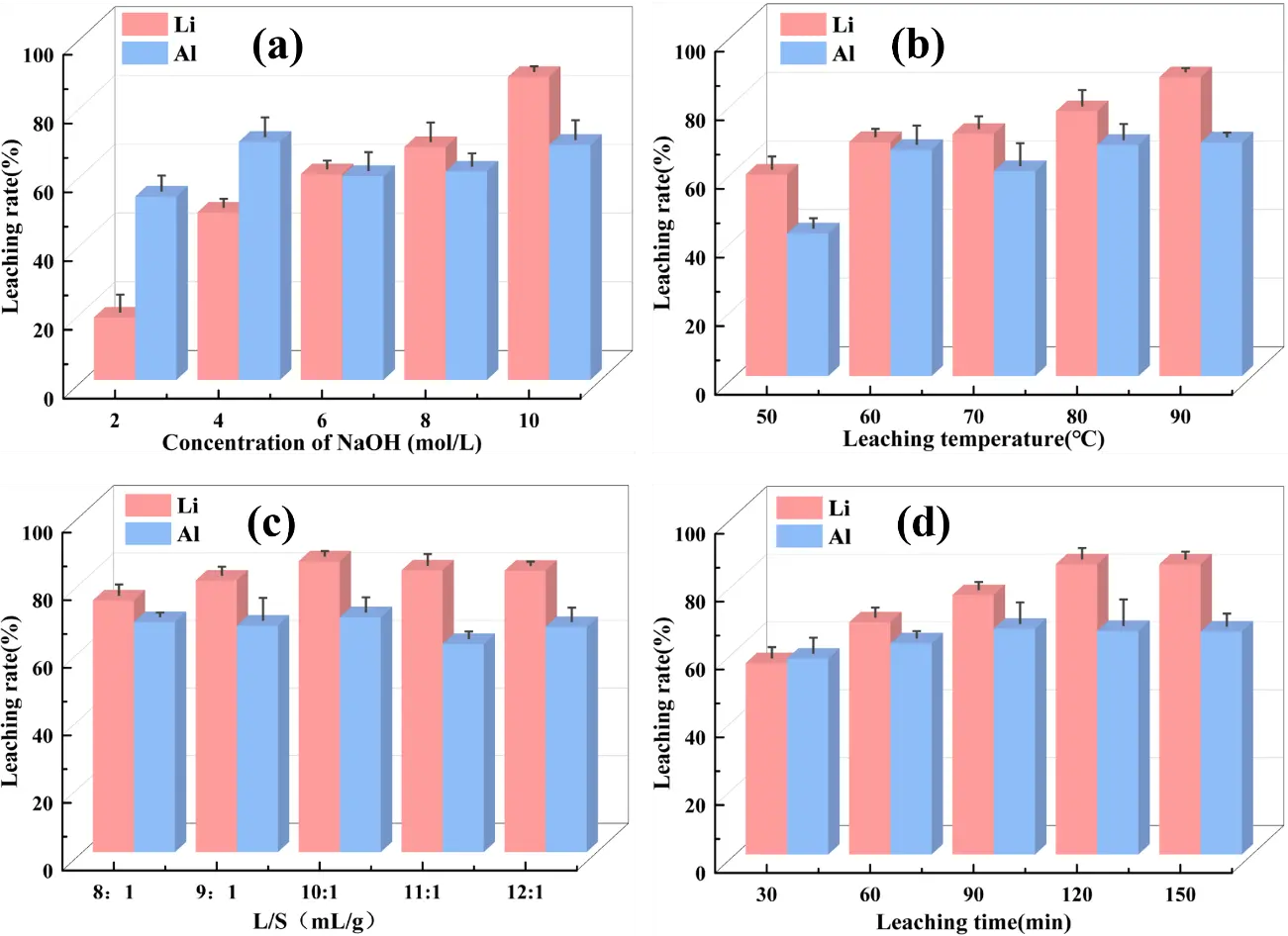
Figure 3. Effect of operating conditions on the leaching rate of Li and Al from SCA of electrolytic aluminum. (a) NaOH concentration; (b) leaching temperature; (c) L/S; (d) leaching time.
Reaction temperature is a key factor affecting Li+ leaching efficiency. As shown in Figure 3b, the Li+ leaching rate increases with rising temperature, reaching 86.34% at 90 °C. This phenomenon is attributed to the enhancement of chemical reaction activity at high temperatures, which increases effective collision between solid-liquid molecules. This speeds up surface chemical reactions and enhances leaching [34]. Notably, when the temperature exceeds 90 °C, the Li+ leaching rate barely changes. Al3+ leaching efficiency follows a similar trend, and higher temperatures are beneficial for dissolving Al in SCA. As depicted in Figure 3c, the Li+ leaching rate was 74.47% at a liquid-solid ratio of 8:1. When the ratio increased further, the Li+ leaching rate rose significantly. This is attributed to insufficient leaching solution volume and inadequate stirring at lower ratios, which prevent thorough mixing and reaction between the solid and liquid phases. At a liquid-solid ratio of 10:1, the solid and liquid phases mixed fully, and the Li+ and Al3+ leaching rates peaked at 86.06% and 69.52%. Figure 3d illustrates that the Li+ leaching rate increases with prolonged leaching time. At 30 min, the Li+ leaching rate stands at 56.41%. At this initial stage, the short duration causes an incomplete reaction, and the cryolite/lithium cryolite structure in the carbon residue does not fully disintegrate, leading to a lower Li+ leaching rate. When the leaching time is extended to 2 h, the Li+ leaching rate peaks at 86.52%. Further extending the time beyond this only marginally increases the rate by 2%. This indicates that extending the time over 2 h has a negligible effect on improving Li leaching efficiency. In summary, the optimal conditions for leaching Li from SCA with NaOH are: NaOH concentration of 10 mol/L, reaction temperature of 90 °C, liquid-solid ratio of 10:1, and leaching time of 2 h. Under these conditions, the maximum Li+ leaching rate reaches 89.46%.
3.2. Leaching Migration Law of Lithium Ions
To clarify the migration and distribution of lithium across different phases during alkaline leaching, we monitored the lithium content in three phases: the leaching solution, triple-washing liquid, and leaching residue, as shown in Figure 4. Figure 4a shows lithium rapidly migrates into the alkaline leaching solution as Li+ with the gradual increase in NaOH concentration, raising the Li+ concentration in the solution. Concurrently, the lithium content in the leaching residue decreases progressively. Only a small amount of lithium remains in the residue as incompletely dissociated lithium cryolite, consistent with the dissolution and transfer chemistry, which show that higher concentrations promote the disintegration of the lithium cryolite lattice, facilitating its release into the liquid phase. Figure 4b suggests that at 50 °C, a significant quantity of lithium is retained in leaching slag, further confirming that low temperatures lead to incomplete reactions. Increasing temperature promotes the release of soluble ions from SCA. Elevating the temperature enhanced the kinetic energy of the solid-liquid system, accelerating the release of soluble from the SCA. When the temperature reaches 90 °C, Li+ concentration in the leaching solution increases significantly, highlighting the positive effect of elevated temperature on leaching. Figure 4c demonstrates that as the liquid-to-solid ratio increases from 8:1 to 10:1, the lithium content in carbon residue decreases notably. At a liquid-to-solid ratio of 10:1, the Li+ content in the leaching solution reaches 75.65%, while the lithium content in the leaching residue is 13.27%, with the remaining 11.08% present in the washing solution. Further increases in the liquid-to-solid ratio cause no notable changes in the lithium content of either the leaching solution or the residue, suggesting an optimal ratio has been reached. In Figure 4d, with prolonged leaching time, lithium continuously migrates from carbon residue into the alkaline leaching solution. At 30 min, due to the short contact time between the carbon residue and the NaOH solution, the structures of cryolite and lithium cryolite are not sufficiently broken down, so much lithium remains unextracted in the carbon residue. When the leaching time reaches 120 min, Li+ concentration in the leaching solution increases significantly. Extending the leaching time further results in negligible changes in the lithium content of the leaching residue and solution. After washing the leaching residue three times with pure water, the Li+ concentration in the washing solution remains at approximately 10%, indicating that water washing effectively dissolves a small portion of the residual lithium in the leaching residue.
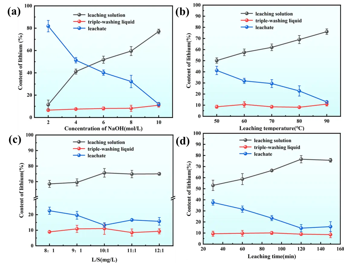
Figure 4. Migration and transformation pattern of Li+ under different leaching conditions (a) NaOH concentration; (b) leaching temperature; (c) L/S; (d) leaching time.
3.3. Transformation of Mineral Phase Structure
3.3.1. SEM and XRD Analysis
Figure 5 demonstrates that as the reaction proceeds, the crystalline structure of Na3AlF6/Na2LiAlF6 disassembles, and the release of soluble ions induces a porous architecture in the residue. At identical magnification, increasing leaching temperature causes the large carbon residue particles to progressively break down into fine granules and fragments. The elevated temperature accelerates the reaction kinetics, rendering the layered morphology of the leaching residue more distinct. Figure 5a shows that the leaching residue maintains large at 50 °C, intact carbon particle aggregates with a dense, layered surface. The EDS spectrum shows a relatively low Na/Al ratio of ~0.62, where sodium comes from both the residual sodium in the original carbon residue and trace amounts of sodium introduced by the NaOH solution. The layered structure is not yet distinct, indicating slow reaction kinetics at this temperature. Figure 5b displays that the large carbon particles begin to break into smaller fragments when the temperature increases to 60 °C, and the layered morphology of the residue becomes more noticeable. The EDS spectrum shows an increased Na/Al ratio of ~2.01, reflecting accelerated ion exchange and the start of new phase formation. Figure 5c indicates that the residue particle size decreases sharply into fine angular fragments at 70 °C. EDS shows Na/Al ratio ~2.11, indicating enhanced reaction kinetics. Figure 5d demonstrates that the large carbon particles are almost completely fragmented into fine granules at 80 °C, and the porous architecture of the residue becomes more evident. The EDS spectrum shows a Na/Al ratio of ~2.85, suggesting substantial formation of NaF and further enrichment of sodium in the residue. Notably, as the temperature increases, the Na content in the EDS spectra rises gradually, accompanied by an upward trend in the Na/Al ratio of the leaching residue, which reaches 3.13 at 90 °C (Figure 5e). Correlating with the XRD patterns of leaching residues at different temperatures, this trend confirms the formation of NaF as a new phase after leaching, driving the increase in the Na/Al ratio. Although lithium cannot be detected by SEM-EDS, this analysis provides critical insights into the overall alkaline leaching mechanism.
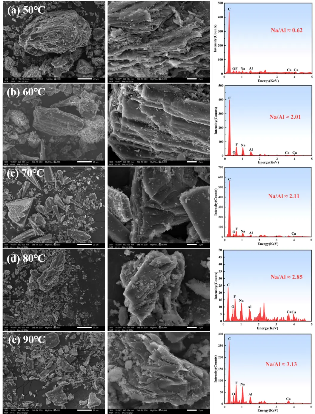
Figure 5. Microscopic morphology and EDS analysis of leaching slag at different temperatures. (a) 50 °C; (b) 60 °C; (c) 70 °C; (d) 80 °C ; (e) 90 °C.
Figure 6 presents the XRD patterns of the raw material and the leaching residue at different liquid-to-solid ratios and leaching times. When the liquid-to-solid ratio is 8:1, the diffraction peaks of Na3AlF6/Na2LiAlF6 in the leaching residue nearly vanish (Figure 6a). As the liquid-to-solid ratio increases from 8:1 to 12:1, the contact efficiency between carbon residue particles and solution improves, thereby enhancing the reaction between carbon residue and alkaline medium. Consequently, the intensity of NaF diffraction peaks in leaching residue also increases, indicating more extensive breakdown of the original crystalline phases and formation of new NaF phases. When the leaching time is only 30 min, residual peaks of Na3AlF6/Na2LiAlF6 are still detectable. As the leaching time is extended from 30 min to 150 min, the reaction between carbon residue and the alkaline solution proceeds more thoroughly (Figure 6b). This leads to a progressive reduction in the intensity of Na3AlF6/Na2LiAlF6 peaks and a corresponding increase in NaF peaks, confirming that longer leaching times promote the disruption of the original crystalline structure.
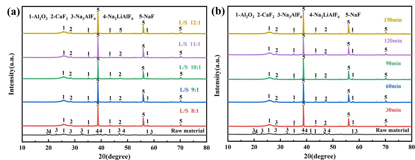
Figure 6. XRD pattern of leaching slag under different conditions; (a) liquid-solid ratios; (b) leaching times.
3.3.2. FT-IR Analysis
As shown in Figure 7, the characteristic absorption peak at 590 cm−1 is attributed to the stretching vibration of [AlF6] in Na3AlF6/Na2LiAlF6 within the carbon residue [35]. After leaching with 2~4 mol/L NaOH solution at 50 °C, this characteristic peak remains prominent, indicating that low temperatures or low-concentration NaOH leaching have a negligible impact on the structures of cryolite and lithium cryolite in the carbon residue. When leaching is performed with a 2 mol/L NaOH solution (Figure 7a), new characteristic absorption peaks appear at 639 cm−1 and 1109 cm−1. The peak at 639 cm−1 corresponds to the stretching vibration of O–H [36], while the peak at 1109 cm−1 is attributed to the stretching vibration of the Li–F bond, suggesting structural transformations and new phase formation during leaching under these conditions. The raw SCA is exposed to ambient air during storage, leading to the adsorption of atmospheric water vapor on its porous surface. The stretching vibration of adsorbed water molecules gives rise to a broad absorption peak in the 3200–3600 cm−1 range. The raw SCA contains residual electrolytes from the electrolytic aluminum production process. These hygroscopic substances absorb moisture from the air and undergo partial hydrolysis, forming surface hydroxyl groups that contribute to the peak intensity. Trace amounts of aluminum hydroxide impurities, generated from the hydrolysis of aluminum-containing phases in the slag, also exhibit characteristic stretching vibrations. At a leaching temperature of 90 °C and NaOH concentration of 10 mol/L (Figure 7b), the characteristic absorption peak at 590 cm−1 completely disappears, indicating that increasing both leaching temperature and NaOH concentration promotes the cleavage of Al–F bonds in Na3AlF6 and Na2LiAlF6. Additionally, the contraction vibration peaks at 643 cm−1, 1632/1638 cm−1, and 3451/3458 cm−1 are attributed to O–H stretching, bending, and stretching vibrations, respectively. The leaching residue is in contact with a high-concentration solution during the alkaline leaching process. Even after washing, trace amounts remain adsorbed on the residual surface, and the hydrolysis of the the residual generates additional hydroxyl groups. The porous structure of the leaching residue readily adsorbs water molecules from the washing solution and ambient air, leading to a prominent peak from adsorbed water. As described in Section 3.1, excessive ions in the leaching solution induce the precipitation of colloidal on the residue surface, forming a passivation layer. The stretching vibration of this is a major contributor to the enhanced peak intensity in the leaching residue compared to the raw SCA. As the liquid-to-solid ratio and leaching time increase, the [AlF6]3− stretching vibration peak of Na3AlF6/Na2LiAlF6 at 590 cm−1 in the leaching residue gradually weakens and eventually disappears, accompanied by the emergence of O–H vibration peaks (Figure 7c,d). This suggests that increasing the liquid-to-solid ratio and leaching time facilitates a more thorough reaction between the carbon residue and solution.
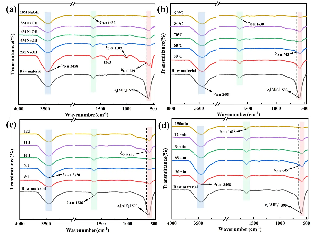
Figure 7. FT-IR plots of raw material and leaching slag under different leaching conditions; (a) NaOH concentration; (b) leaching temperature; (c) L/S; (d) leaching time.
3.3.3. XPS Analysis
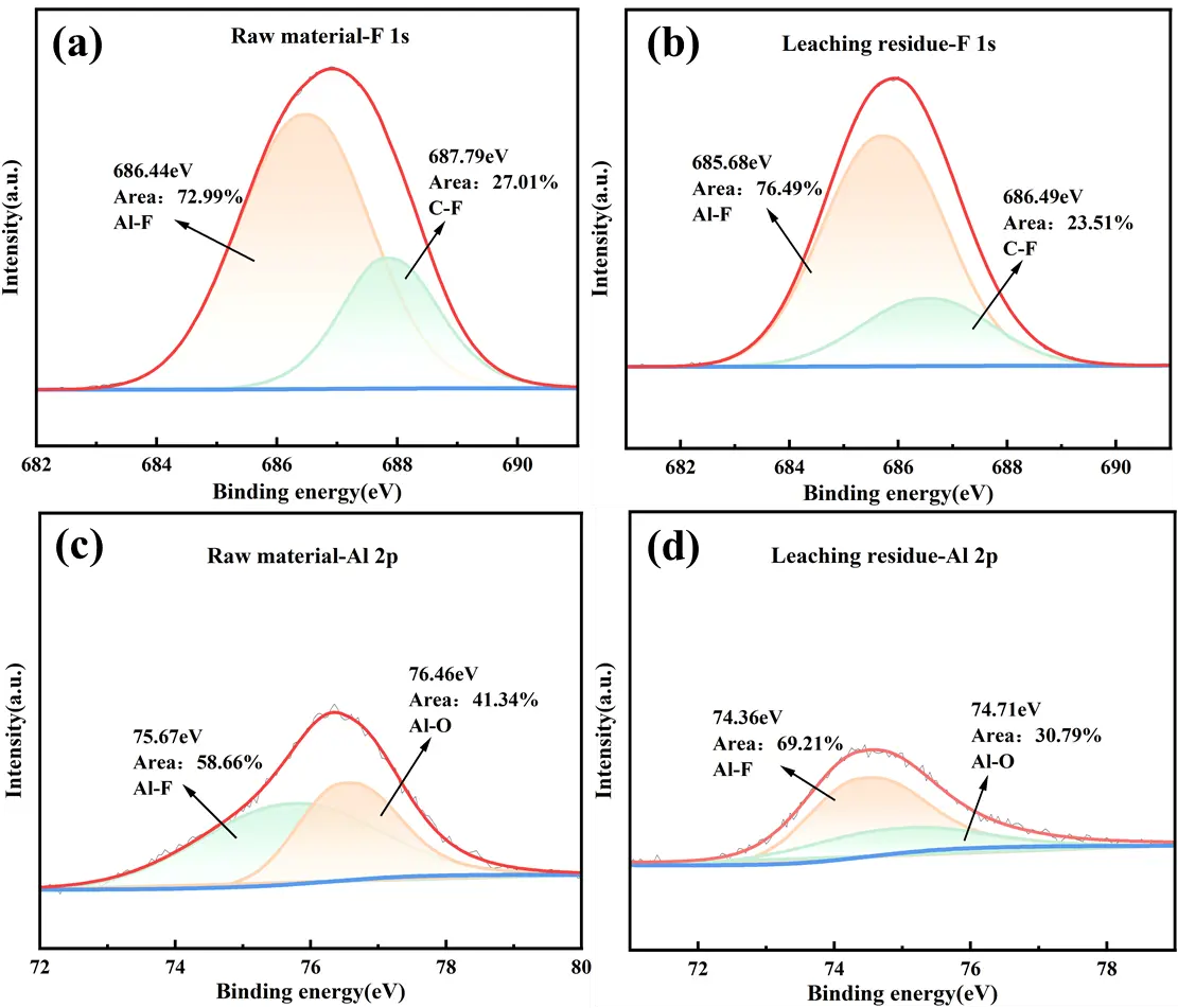
To clarify the chemical bond and microstructural evolutions during lithium extraction from SCA via NaOH leaching, XPS peak fitting of F1s and Al 2p was performed. As depicted in Figure 8a,b, the F1s XPS spectra of the raw material and leaching residue show that the 686.44 eV peak in the raw material corresponds to the characteristic peak of Na–Al–F in Na3AlF6/Na2LiAlF6. After leaching with a 10 mol/L NaOH solution, this characteristic peak shifts to a lower binding energy of 685.68 eV, attributed to the destruction of the cryolite phase and the release of Na+ and F− during the alkaline leaching process. Additionally, the peak at 687.79 eV corresponds to the characteristic peak of the C–F bond. Fluorine, being highly electronegative and reactive, readily forms stable C–F bonds with carbon [37]. The presence of C–F bonds imparts excellent hydrophobicity to the leaching residue, which is beneficial for solid-liquid separation after leaching. Figure 8c,d suggested that the peak at 75.67 eV corresponds to the Al–F bond in Na3AlF6/Na2LiAlF6. Following NaOH leaching, the Al–F bond binding energy shifts to a lower field at 74.36 eV, which is attributed to the destruction of the cryolite structure and the leaching of Al3+ and F− into the solution. The peak at 76.46 eV in the raw material corresponds to the binding energy of the Al–O bond in Al2O3 [38]. Its binding energy increases relatively after leaching, indicating the breakdown of Al2O3 in the raw material. These results are consistent with the findings from the aforementioned XRD and FT-IR analyses.
3.4. Extraction and Recovery of Lithium Leaching Solution
After alkaline leaching treatment, most of the lithium in the carbon residue transfers into NaOH solution, where it reacted with water to form water-soluble LiOH. Simultaneously, other elements also react with NaOH and dissolve into the leaching solution. Consequently, the leaching solution contains Li+ along with metal ions such as Al3+, Ca2+, and Na+ (Table 2). Under alkaline conditions, HBTA and TOPO exhibit significant synergistic extraction for Li+, enabling back-extraction of Li+ from the HBTA-TOPO system using a specified concentration of HCl [39].
Table 2. Concentrations of major ions in leach solution.
|
Ion |
Li+ |
Na+ |
Ca2+ |
Al3+ |
F− |
|---|---|---|---|---|---|
|
Concentration (g/L) |
1.25 |
216.05 |
1.18 |
10.04 |
16.89 |
As depicted in Figure 9, the extraction system showed low Li+ extraction efficiency when using the synergistic extractant ratios of either 0.01 mol/L HBTA + 0.09 mol/L TOPO or 0.09 mol/L HBTA + 0.01 mol/L TOPO. Experimental observations indicate that using HBTA alone or an insufficient TOPO concentration led to obvious emulsification at the liquid-liquid interface, hindering phase separation. As the HBTA concentration gradually increased, both the extraction efficiency of Li+ and the lithium distribution ratio peaked at 0.05 mol/L HBTA (Figure 9a), which are consistent with the findings reported by Zhang.
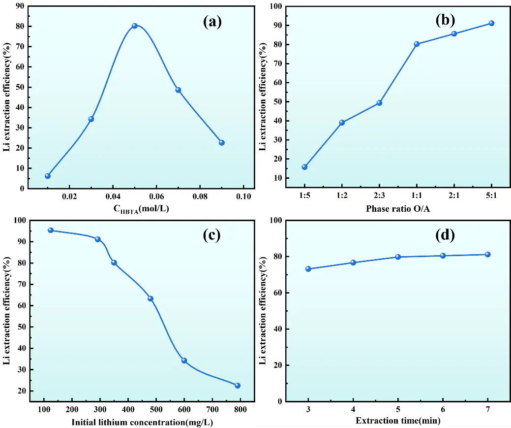
Figure 9. Effect of operating conditions on Li+ extraction efficiency. (a) HBTA concentration; (b) O/A; (c) Initial lithium concentration; (d) Extraction time.
When the concentration ratio of HBTA to TOPO is 1:1, the extraction efficiency of Li+ peaks its optimum at 80.18%. Under these conditions, the extraction system achieves rapid phase separation, with a clear interface between the aqueous and organic phases. TOPO, acting as a surfactant, effectively improves the solubility of metal-organic complexes in the organic phase and prevents the formation of interfacial precipitates. Research by Zhang et al. [33] indicates that Li+ can exchange with the hydrogen atoms of the hydroxyl groups in HBTA, while TOPO, as an excellent electron donor, can effectively replace the water molecules surrounding Li+ and form stable complexes with Li+ and HBTA.
As shown in Figure 9b, when the organic/aqueous (O/A) ratio increases from 1:5 to 1:1, the lithium extraction efficiency escalates from 15.75% to 80.18%. Further increasing the O/A ratio to 5:1 enhanced the extraction efficiency to 91.09%. This indicates that a larger organic phase volume expands the contact area between the organic extractant and the aqueous phase, facilitating the transfer of lithium ions into the organic phase and thereby improving extraction efficiency. However, considering operational costs and practical process requirements, the extraction efficiency at an O/A ratio of 1:1 (80.18%) was deemed sufficiently high, as further increasing the phase ratio only yielded marginal efficiency improvements. Therefore, an O/A ratio of 1:1 was adopted for subsequent experiments. Ionic strength affects the activity coefficients of ions in solution, thereby regulating the equilibria of complexation reactions and phase-transfer processes. High ionic strength compresses the electric double layer around ions, reduces the electrostatic repulsion between Li+ and the functional groups of HBTA, and may promote the formation of Li+-HBTA complexes, thereby improving lithium extraction efficiency [40]. However, excessive ionic strength may also cause salting-out effects, reducing the solubility of the organic extractant in the organic phase and leading to emulsification, which is consistent with the emulsification phenomenon observed when the extractant ratio is inappropriate.
Figure 9c shows that the initial lithium concentration in the aqueous phase exerts a pronounced influence on Li+ extraction efficiency. Experimental results demonstrate that as the initial lithium concentration in the aqueous phase increases, the Li+ extraction efficiency of the HBTA-TOPO synergistic extraction system gradually declines. When the initial lithium concentration remains in the low range (<100 mg/L), the extraction system exhibits excellent performance, with Li+ extraction efficiency exceeding 95%. Conversely, when the initial concentration exceeds 350 mg/L, the extraction efficiency decreases significantly. This phenomenon can be attributed to saturation of active extraction sites for Li+ in the organic phase, consistent with the findings reported by Zhang [33]. Therefore, extraction experiments should avoid the use of high initial lithium concentrations. In cases where the lithium concentration in the aqueous phase is high, the lithium loading capacity and extraction efficiency of the system can be improved by increasing the concentration of HBTA-TOPO in the organic phase or adopting a multi-stage countercurrent extraction process.
Figure 9d shows that the Li+ extraction efficiency increases rapidly with prolonged extraction time and gradually approaches equilibrium. At an extraction time of 5 min, the Li+ extraction efficiency attains 80.13%. The rate of efficiency improvement decelerates sharply after 5 min, suggesting that the system has reached equilibrium. By integrating kinetic analysis with economic considerations, the optimal extraction time is determined to be 5 min. In summary, the optimal conditions for the HBTA-TOPO synergistic extraction system to extract Li+ from an alkaline leaching solution are as follows: a HBTA/TOPO concentration ratio of 1:1, an initial lithium concentration of 350 mg/L, an O/A ratio of 1:1, and an extraction time of 5 min. Under these conditions, the extraction efficiency of Li+ reaches 81.54%.
Temperature exerts a dual regulatory effect on both lithium extraction and cryolite regeneration processes, which is closely associated with reaction kinetics, mass transfer efficiency, and solubility equilibrium. In the HBTA-TOPO synergistic extraction of lithium, although the original experimental design focused on extraction time, O/A ratio, and extractant concentration, temperature indirectly affects extraction efficiency by modifying the viscosity of the organic phase and the stability of Li+-HBTA-TOPO complexes [40]. A moderate increase in temperature can reduce the viscosity of the organic phase, expand the contact area between the organic and aqueous phases, and accelerate the rate of Li+ mass transfer across the phase interface, thereby shortening the time required to reach extraction equilibrium. However, excessive temperature may weaken the coordination interaction between TOPO (an electron donor) and Li+, leading to decomposition of stable complexes and a decline in extraction efficiency.
3.5. Restoration of Carbonized Cryolite from Residual Liquid
Table 3 displays the concentrations of major ions in the raffinate. After performing the extraction experiments under optimal conditions, it was observed that the Li+ concentration in the raffinate decreased significantly, while the concentrations of other ions (Na+, Ca2+, Al3+) changed only slightly. Therefore, the raffinate and washing solution from the leaching residue were used for subsequent studies on cryolite regeneration.
Table 3. Concentration of major metal ions in the extract.
|
Ion |
Li+ |
Na+ |
Ca2+ |
Al3+ |
F− |
|---|---|---|---|---|---|
|
Concentration (g/L) |
0.24 |
210.6 |
1.12 |
9.96 |
16.87 |
3.5.1. Simulation of the Existence State of Al–F Component in Solution
The ion speciation simulation was performed using Medusa. To ensure consistency with experimental conditions, the initial concentrations of Al3+, F−, and Na+ were 0.1 mol·L−1, 0.6 mol·L−1, and 0.3 mol·L−1), temperature (25 °C), and ionic strength (0.1 mol·L−1) into the software. Figure 10 simulates the influence of different pH levels on the distribution of Al–F complexes in solution. The primary Al–F complex ions in solution are AlF2+ and AlF2+ at pH from 0 to 4. The solution pH significantly affects the cryolite synthesis process. As pH increases, the Na+ concentration in solution rises, promoting a shift in the reaction equilibrium (Equation (7)) toward cryolite precipitation(Table 4). According to the Hard and Soft Acids and Bases (HSAB) theory [41], Al3+ (hard acid) and F− (hard base) referentially combine in solution to form stable AlF63− complexes. Subsequently, these AlF63− complexes react with Na+ to generate cryolite precipitate. During the reaction, AlF52− and AlF63− sequentially appear in solution, with AlF63− gradually becoming the dominant Al–F complex ion. Notably, AlF63− serves as the key intermediate for cryolite synthesis. As pH approaches 8, amorphous Al(OH)3 starts to precipitate due to enhanced OH− driving reaction (8), forming alongside cryolite. Above pH 9, cryolite redissolves in alkaline solution. With nearly all fluoride ions precipitating as cryolite at pH 9 for maximal fluorine recovery, this pH is optimized considering all factors. The product at pH = 9 showed sharp diffraction peaks matching the standard cryolite (Na3AlF6, PDF#15-0776), with no obvious characteristic peaks of amorphous Al(OH)3 (broad peaks at ~18° and ~38°). At pH > 9, weak Al(OH)3 peaks appeared, confirming increased impurity formation. The product at pH = 9 exhibited well-defined cubic cryolite crystals, while at pH > 9, flocculent Al(OH)3 aggregates adhered to cryolite surfaces, reducing product purity. At pH = 9, the dominant Al–F complex is AlF63− (the key intermediate for cryolite formation), and the fraction of Al(OH)3 is still minimal (avoiding excessive impurity precipitation). pH = 9 achieves the highest fluorine recovery (~98%) and minimal Al(OH)3 contamination. At pH < 9, incomplete Al–F complexation (dominated by AlF4−/AlF52−) limits cryolite precipitation. At pH > 9, cryolite redissolves (driven by Al(OH)4− formation), and Al(OH)3 precipitation increases, degrading both recovery and purity. Thus, pH = 9 balances maximal fluorine utilization, product purity, and process stability.
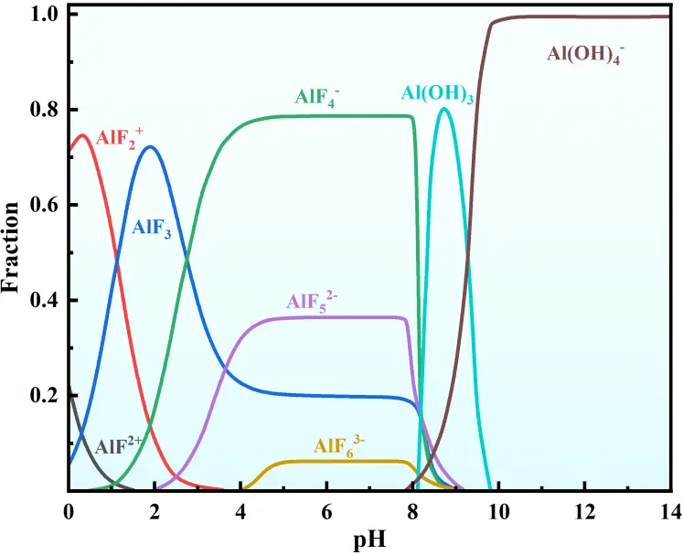
Table 4. Some of the possible reaction equations and their equilibrium constants during a carbonation reaction [42].
|
Serial Number |
Reaction Equation |
logK |
|---|---|---|
|
1 |
AlF2+ ⇌ Al3+ + F− |
−7.239 |
|
2 |
AlF2+ ⇌ Al3+ + 2F− |
−12.710 |
|
3 |
AlF3 ⇌ Al3+ + 3F− |
−17.521 |
|
4 |
AlF4− ⇌ Al3+ + 4F− |
−18.627 |
|
5 |
AlF52− ⇌ Al3+ + 5F− |
−19.601 |
|
6 |
AlF63− ⇌ Al3+ + 6F− |
−19.720 |
|
7 |
Na3AlF6(s) ⇌ 3Na+ + AlF63− |
−12.784 |
|
8 |
Al3+ + 3OH− ⇌ Al(OH)3(s) |
29.844 |
|
9 |
Al3+ + 4H2O ⇌ Al(OH)4− + 4H+ |
−19.518 |
3.5.2. Influence of Process Conditions on Cryolite Regeneration
Figure 11a shows that cryolite yield initially increases with the rise in CO2 flow rate and then gradually stabilizes. When the CO2 flow rate is between 200 L/h and 250 L/h, the cryolite yield peaks at 76.54%. At this point, the moderate reaction rate allows cryolite crystals to precipitate and grow uniformly, contributing to the higher yield. At a CO2 flow rate of 50 L/h, cryolite yield is notably lower, mainly because a slower mass transfer rate at lower CO2 flow rates leads to a gradual decrease in solution pH, making it difficult to achieve optimal nucleation conditions for cryolite. However, when the CO2 flow rate exceeds 250 L/h, although the reaction rate accelerates, the excessively rapid nucleation rate results in numerous fine crystal nuclei that are difficult to grow into stable crystals. Therefore, controlling the CO2 flow rate within the range of 200–250 L/h is crucial for the controllable growth of cryolite crystals. Reaction temperature is another key control parameter in the cryolite synthesis process. Figure 11b illustrates that cryolite yield increases with rising temperature, peaking at 76.02% at 70 °C. This phenomenon can be attributed to the following: at low temperatures (<70 °C), the solubility of CO2 in the reaction system is relatively high, which facilitates its reaction with sodium fluoride and sodium chlorate to form a cryolite precipitate. However, excessively low temperatures reduce the reaction rate constant and increase solution supersaturation, both of which are unfavorable for cryolite crystal nucleation and growth [43]. As the reaction temperature rises, molecular diffusion accelerates, promoting the formation of cryolite. Consequently, the cryolite yield also increases. When the temperature exceeds 70 °C, the solubility of cryolite significantly increases, causing the reaction equilibrium to shift in the reverse direction and resulting in a decline in yield. As shown in Figure 11c, the cryolite yield increases with prolonged reaction time. During the initial stage (40–100 min), the yield significantly rises from 53.47% to 73.49%, primarily due to the consumption of reactant concentrations and the progression of the product crystallization process. When the reaction time exceeds 100 min, the growth in cryolite yield decelerates, reaching 75.34% at 120 min, suggesting that the reaction system approaches equilibrium.
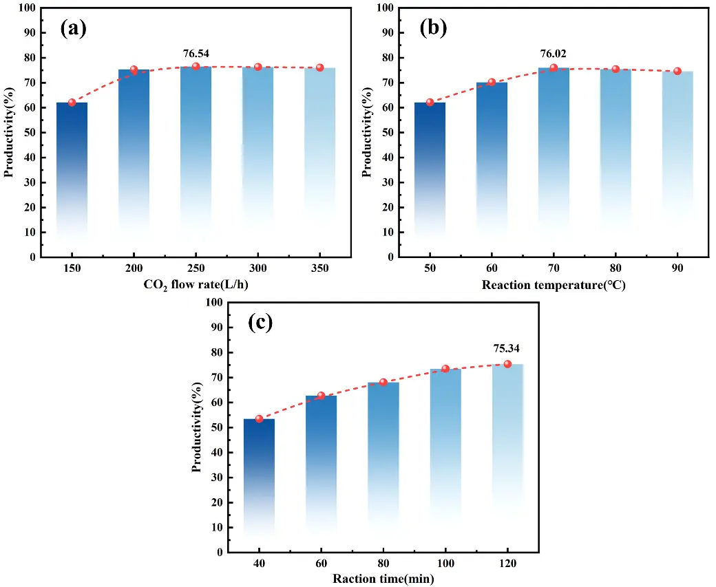
Figure 11. Carbonization of residual solution to synthesize cryolite. (a) CO2 flow rate; (b) reaction temperature; (c) reaction time.
3.6. Characterization of Regenerated Cryolite
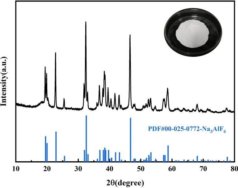
Under the optimal process conditions, the resulting white product was washed twice using hot water, then dried and ground. Figure 12 indicates that the diffraction pattern of the experimental product shows a good match with the standard cryolite card (PDF#00-025-0772). XRD diffraction peaks of the experimental product are sharp, indicating excellent crystallinity. Although minor discrepancies in peak intensities exist between the experimental and standard patterns, these are primarily attributed to preferred orientation during crystal growth. Notably, the diffraction pattern exhibits no significant impurity peaks, fully consistent with the standard phase characteristics of cryolite.
Under the optimal conditions of 70 °C reaction temperature, pH 9, and CO2 flow rate of 100–150 L/h, the cryolite exhibits a well-defined and regular morphology with typical smooth, planar surfaces. The crystal edges are well-defined, displaying distinct octahedral or quasi-octahedral shapes (Figure 13a,b). During crystal growth, newly formed cryolite particles adsorb onto and aggregate with existing crystals, leading to continuous enlargement of crystal size. We acknowledge that EDS analysis is a semi-quantitative surface elemental characterization technique, which is primarily used to qualitatively identify the elemental composition of the synthetic product and semi-quantitatively analyze the relative content of surface elements, rather than serving as the official method for verifying compliance with product purity standards. The EDS results (51.71% F, 33.92% Na, 14.37% Al) presented in the manuscript are only intended to intuitively reflect the elemental distribution characteristics of the cryolite product surface (Figure 13c,d), meeting the composition requirements for high-molecular-ratio cryolite in GB/T 4291-2017 Cryolite standard (F ≥ 52%, Na ≤ 33%, Al ≥ 12%). These results provide preliminary evidence for the elemental composition of the product, which is consistent with the phase identification results of XRD.
3.7. Analysis of Process Flow
3.7.1. Reaction Mechanism
Figure 14 illustrates the mechanism of simultaneous synthesis of cryolite during alkali leaching for lithium extraction from SCA. Lithium replaces part of the sodium atoms in cryolite through isomorphism to form lithium cryolite (Na3AlF6−xLix). Extracting lithium from SCA requires breaking the stable structure of lithium cryolite. Under strongly alkaline conditions (pH > 10), hydroxide ions (OH−) disrupt the Al–F coordination bonds via nucleophilic substitution in the lithium cryolite within the waste slag, releasing lithium ions, sodium ions, aluminum ions, and fluoride ions. Subsequently, Na+ combines with F− to form sodium fluoride (NaF), which adheres to the slag surface due to the common-ion effect of the high-concentration sodium hydroxide (NaOH), thereby inhibiting hydrolysis. Li+ can exchange with the hydrogen atoms of hydroxyl groups in HBTA, while TOPO, as an excellent electron donor, effectively replaces the water molecules around Li+ and forms a stable complex with Li+ and HBTA. When carbon dioxide is passed into the raffinate, CO2 reacts with OH− to reduce the pH from 10–12 to 8–9. This pH change promotes the re-coordination of tetrahydroxyaluminate ions ([Al(OH)4]−) with F− to form hexafluoroaluminate ions ([AlF6]3−). When the concentration of c(Na+)3·(c([AlF6]3−)) exceeds the solubility product of cryolite, controlling the CO2 flow rate at 100–150 L/h enables [AlF6]3− and Na+ to crystallize. Due to the extraction separation of Li+ and filtration of impurity precipitates, the product purity meets the requirements of GB/T 4291-2017. This process offers advantages such as high lithium extraction efficiency, high cryolite purity, recyclable NaOH, and no release of harmful gases, demonstrating significant environmental friendliness.
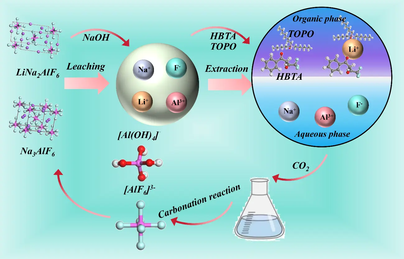
Figure 14. Schematic diagram of the phase transition of lithium ore extracted by alkaline leaching of SCA from electrolytic aluminum.
3.7.2. Process Novelty
Compared with the existing SCA treatment processes, the proposed process core adaptation mechanism is the selective destruction of Al–F coordination bonds by alkaline leaching and the specific complexation of HBTA-TOPO for Li+. Realizes simultaneous extraction of Li and regeneration of cryolite, avoiding fluorine resource waste and fluoride pollution caused by traditional processes that only recover Li and discharge fluorine-containing wastewater; realizes the immobilization of toxic F− into high-value cryolite [40], realizing “waste treatment by waste”. The HBTA-TOPO organic phase can be reused after HCl back-extraction, reducing reagent consumption and environmental load. The proposed process is not only applicable to electrolytic aluminum SCA but also has good adaptability to other lithium-fluorine-containing industrial solid wastes, including Lithium battery recycling slag containing fluorine-containing binders; fluorochemical industry waste residue with lithium impurities; and other electrolytic aluminum solid wastes (e.g., cathode slag, electrolyte waste).
3.7.3. Limitations and Optimization Directions
Although the process achieves efficient lithium extraction and cryolite regeneration, there are still two main limitations that need to be optimized for industrial-scale. Marginal emulsification and phase separation loss of HBTA-TOPO may cause organic pollution and increase production costs; subsequent research can add activated carbon adsorption or membrane separation steps to recover residual extractants in the aqueous phase, and modify the extractant with surfactants to improve phase separation efficiency. The regenerated cryolite has regular octahedral morphology but uneven particle size; subsequent research can optimize the carbonization rate by adding crystal seeds to control crystal growth and obtain uniform particle size cryolite meeting industrial application requirements. In addition, the high-concentration alkaline solution and fluoride ions may cause corrosion to metal equipment, and the use of corrosion-resistant materials or equipment inner lining modification is the key to industrial application.
3.7.4. Environmental and Industrial Application Value
From the perspective of circular economy and green chemical industry, this process realizes the transformation of electrolytic aluminum SCA from “hazardous waste” to “resource raw material”, which not only solves the environmental pollution problem caused by SCA stockpiling but also provides a new source of lithium resources for the new energy industry and a recyclable cryolite raw material for the aluminum smelting industry. The process has the characteristics of simple operation, mild conditions and low energy consumption, which has good industrial application prospects. The research idea of “resource recovery + waste regeneration” can also provide a reference for the high-value utilization of other multi-component industrial solid wastes, and has important promotional significance.
In summary, this study clarifies the intrinsic mechanism of alkaline leaching-lithium extraction-cryolite regeneration from SCA, develops a novel synergistic recovery process, and verifies its broad applicability to similar lithium-fluorine-containing solid wastes. Through targeted optimization of the above limitations, the process can be further scaled up, providing a technical solution for the resource utilization of electrolytic aluminum solid wastes and the green recovery of lithium/fluorine resources.
4. Conclusions
This study addresses the critical challenge of efficiently recovering lithium from SCA (a byproduct of aluminum electrolysis) while simultaneously producing high-value cryolite, offering a sustainable, closed-loop solution for resource utilization. Our research delivers several key advances and meaningful outcomes that advance the state of the art:
- (1)
-
At NaOH concentration 10 mol/L, reaction temperature 90 °C, liquid-to-solid ratio 10:1, and reaction time 120 min, the maximum Li+ leaching rate reaches 89.46%. With increasing NaOH concentration, leaching temperature, liquid-to-solid ratio, and leaching time, lithium in the carbon residue rapidly migrates into the alkaline leaching solution as Li+. Correspondingly, the lithium content in the leaching residue decreases, and pure water washing can effectively dissolve the small amount of residual lithium in the leaching residue.
- (2)
-
The diffraction peaks of cryolite and lithium cryolite in the leaching residue are largely absent, whereas those of NaF have emerged. Following alkaline leaching, the carbon residue assumes a loose lamellar structure. Alkaline conditions induce cleavage of Al–F bonds in Na3AlF6 and Na2LiAlF6, disrupt the structures of cryolite and lithium cryolite, and release numerous soluble ions. This mechanism not only resolves the low lithium release efficiency of traditional methods but also provides a clear theoretical basis for breaking stable fluorometallate complexes.
- (3)
-
The optimal conditions for extracting Li+ from lithium-rich alkaline leaching solutions in the HBTA-TOPO synergistic extraction system are: a HBTA-to-TOPO concentration ratio of 1:1, an initial lithium concentration of 350 g/L, an O/A ratio of 1:1, and an extraction time of 5 min. Under these conditions, the Li+ extraction efficiency reaches 81.54%. This system outperforms conventional extraction processes by combining the chelating ability of HBTA with the phase-transfer capability of TOPO, enabling rapid and selective lithium enrichment from high-alkali leachates. This advance lays a foundation for scalable lithium recovery from complex alkaline solutions.
- (4)
-
With a CO2 flow rate of 250 L/h, reaction temperature of 70 °C, reaction pH of 9, and reaction time of 120 min, the cryolite yield reaches 76.54%, which meets industrial purity standards. Among these factors, reaction temperature and solution pH significantly affect the yield and morphology of cryolite. The synthesized product exhibits a well-defined octahedral morphology, excellent crystallinity, and a smooth surface, demonstrating precise control over product quality through pH and temperature regulation. This not only converts raffinate waste into a high-value industrial material but also avoids the environmental risks associated with the discharge of fluorine-containing wastewater.
- (5)
-
The integrated “alkaline leaching-synergistic extraction-carbonation” process establishes a closed-loop system that simultaneously recovers lithium and produces high-quality cryolite from carbon residue waste. This approach reduces solid waste accumulation, mitigates fluorine pollution, and creates economic value from industrial byproducts, providing a viable technical paradigm for the sustainable treatment of similar metallurgical wastes. Our findings offer practical guidance for the industrial-scale recovery of lithium and synthesis of fluorometallate products, with significant implications for advancing circular economy practices in the aluminum and lithium industries.
Acknowledgement
The authors are grateful for the funding provided by Shanxi Province Central Government Guided Local Science and Technology Development Fund Project (YDZJSX2022A004), and Technology Achievement Transformation Project of Lvliang (2022XDHZ15).
Author Contributions
Conceptualization, Y.Q. and J.G.; Methodology, Z.P.; Investigation, Y.Q. and D.L.; Writing—Original Draft Preparation, X.N. and Y.L.; Writing—Review & Editing, X.N. and X.L.; Supervision, Y.Q. and Z.P.
Ethics Statement
Not applicable.
Informed Consent Statement
Not applicable.
Data Availability Statement
All datasets generated and/or analyzed during the current study are publicly available to ensure the transparency and reproducibility of the research findings.
Funding
This research was funded Shanxi Province Central Government Guided Local Science and Technology Development Fund Project (YDZJSX2022A004), and Technology Achievement Transformation Project of Lvliang (2022XDHZ15).
Declaration of Competing Interest
The authors declare that they have no known competing financial interests or personal relationships that could have appeared to influence the work reported in this paper.
References
- Scrosati B, Garche J. Lithium batteries: Status, prospects and future. J. Power Sources 2010, 195, 2419–2430. DOI:10.1016/j.jpowsour.2009.11.048 [Google Scholar]
- Baudino L, Santos C, Pirri CF, La Mantia F, Lamberti A. Recent Advances in the Lithium Recovery from Water Resources: From Passive to Electrochemical Methods. Adv. Sci. 2022, 9, 2201380. DOI:10.1002/advs.202201380 [Google Scholar]
- Thirumurugan A, Govindaraj R, Dhanabalan S, Sakthivel P, Chidhambaram N, Udayabhaskar R, et al. Strategic analysis of lithium resources by addressing challenges and opportunities for sustainable electric vehicle battery development in the era of global EV domination. Z. Fur Phys. Chem. 2025, 239, 457–465. DOI:10.1515/zpch-2023-0524 [Google Scholar]
- Tabereaux A, Alcorn T, Luketrembley A. Lithium-Modified Low Ratio Electrolyte Chemistry for Improved Performance in Modern Reduction Cells. J. Electrochem. Soc. 2020, 167, 132502. DOI:10.1007/978-3-319-48156-2_11 [Google Scholar]
- Li H, Du J. Research on Circular Economy of Mineral Resources in China: Bauxite Resources in Shanxi Province as an Example. Geol. Resour. Manag. Sustain. Dev. 2009. [Google Scholar]
- Zhang Y, Zhang J. Study on the Occurrence State of Lithium in Low-Grade Diasporic Bauxite from Central Guizhou Province, China. JOM 2019, 71, 4594–4599. DOI:10.1007/s11837-019-03670-x [Google Scholar]
- Cui P, Qin B, Haarberg GM. The Behavior of Additives LiF, MgF2 and KF on Current Efficiency in Aluminium Electrolysis. J. Electrochem. Soc. 2019, 166, D559–D563. DOI:10.1149/2.0431913jes [Google Scholar]
- Chen Y, Li P, Bu X, Chehreh Chelgani S, Kong Y, Liang X. Resource utilization strategies for spent pot lining: A review of the current state. Sep. Purif. Technol. 2022, 300, 121816. DOI:10.1016/j.seppur.2022.121816 [Google Scholar]
- Leng M, Li W, Liu Q. Study of lithium extraction and fluoride removal from waste aluminum electrolyte by the roasting-leaching method. J. Ind. Eng. Chem. 2025, 147, 201–209. DOI:10.1016/j.jiec.2024.12.012 [Google Scholar]
- Liu CC, Qu PC, Zhan MZ, Tan ZL, Wu GX, Wang YJ, et al. Preparation of graphite anodes for lithium-ion batteries from aluminum electrolysis spent cathode carbon. J. Energy Storage 2025, 131, 117633. DOI:10.1016/j.est.2025.117633 [Google Scholar]
- Chen R. Ionic liquids-mediated recovery of metals from spent batteries. J. Ion. Liq. 2023, 3, 100070. DOI:10.1016/j.jil.2023.100070 [Google Scholar]
- Kordloo M, Boroumand Z, Abdollahi H, Rezaei A, Ghorbani Y, Solgi A. Lithium recovery from waste aluminum electrolyte via bioleaching: Comparative insights into acidic and alkaline pathways using Aspergillus niger and Glutamicibacter nicotianae. Waste Manag. 2025, 206, 115043. DOI:10.1016/j.wasman.2025.115043 [Google Scholar]
- Zhou H, Cao Z, Ma B, Wang C, Chen Y. Selective and efficient extraction of lithium from spodumene via nitric acid pressure leaching. Chem. Eng. Sci. 2024, 287, 119736. DOI:10.1016/j.ces.2024.119736 [Google Scholar]
- Zhou H, Liu Y, Ma B, Wang C, Chen Y. Efficient lithium extraction from low-grade clay-type lithium ore via nitric acid pressure leaching. J. Environ. Chem. Eng. 2025, 13, 118653. DOI:10.1016/j.jece.2025.118653 [Google Scholar]
- Yang J, Tao W, Li J, He J, Wang Z. Efficient lithium recycling from waste aluminum electrolytes through an environmentally friendly process. Chem. Eng. J. 2025, 512, 162431. DOI:10.1016/j.cej.2025.162431 [Google Scholar]
- Tian J, Chen B, Xia H, Yang W, Dai L, Zhang L. Ultrasound-assisted enhanced leaching of lithium and fluoride compounds from waste cathode carbon: Comprehensive recovery and leaching mechanism. Sep. Purif. Technol. 2025, 354, 129190. DOI:10.1016/j.seppur.2024.129190 [Google Scholar]
- Dong L, Jiao F, Liu W, Wang C, Wang D, Qin W. Selective extraction of lithium and solidified fluoride from overhaul slag by the calcium sulfate roasting and water leaching. Miner. Eng. 2024, 217, 108943. DOI:10.1016/j.mineng.2024.108943 [Google Scholar]
- Liu S, Hu Q, Song X, Xiong X, Li X, Wang Z, et al. Causticization of electrolytic aluminum slag for selective lithium recovery and fluorine fixation. J. Hazard. Mater. 2025, 492, 138272. DOI:10.1016/j.jhazmat.2025.138272 [Google Scholar]
- Wu S, Tao W, Zheng Y, Ge H, He J, Yang Y, et al. A novel approach for lithium recovery from waste lithium-containing aluminum electrolyte by a roasting-leaching process. Waste Manag. 2021, 134, 89–99. DOI:10.1016/j.wasman.2021.08.011 [Google Scholar]
- Cui L, Wang W, Chao X, Gao J, Cheng F. Efficient lithium recovery from electrolytic aluminum slag via an environmentally friendly process: Leaching behavior and mechanism. J. Clean. Prod. 2024, 439, 140800. DOI:10.1016/j.jclepro.2024.140800 [Google Scholar]
- Wu S, Tao W, Zheng Y, Yang Y, Yu J, Cui J, et al. Novel process for the extraction of lithium carbonate from spent lithium-containing aluminum electrolytes by leaching with aluminum nitrate and nitric acid. Hydrometallurgy 2020, 198, 105505. DOI:10.1016/j.hydromet.2020.105505 [Google Scholar]
- Cheng N, Jiang R, Cheng Y, Hu L, Jiang S, Li M, et al. Chelator auxiliary electrodialysis (CAED) for efficient and sustainable lithium extraction and magnesium co-recovery from salt lake brines. Chem. Eng. J. 2025, 521, 166666. DOI:10.1016/j.cej.2025.166666 [Google Scholar]
- Salakjani NK, Singh P, Nikoloski AN. Acid roasting of spodumene: Microwave vs. conventional heating. Miner. Eng. 2019, 138, 161–167. DOI:10.1016/j.mineng.2019.05.003 [Google Scholar]
- Gao J, Liu W, Sui J, Zhang Z, Dong Y, Wang D, et al. Piezocatalytic lithium extraction from aqueous solutions. Nano Energy 2025, 142, 111186. DOI:10.1016/j.nanoen.2025.111186 [Google Scholar]
- Wang L, Zhang P, Guo Z, Zhang Y, Wang Y. Electrochemical lithium extraction by the faradaic materials: Advances, challenges and enhancement approaches. Acta Phys.-Chim. Sin. 2025, 41, 2403011. DOI:10.1016/j.actphy.2025.100127 [Google Scholar]
- Yelatontsev D, Mukhachev A. Processing of lithium ores: Industrial technologies and case studies—A review. Hydrometallurgy 2021, 201, 105578. DOI:10.1016/j.hydromet.2021.105578 [Google Scholar]
- Zhang X, Wang C, Pei T, Gao F, Hao X, Xing L, et al. Underlying physics analysis and performance evaluation of electrochemical Li+ extraction from low-quality brines via a spatiotemporal distribution model. Sep. Purif. Technol. 2025, 364, 132351. DOI:10.1016/j.seppur.2025.132351 [Google Scholar]
- Dumestre A, Chone T, Portal J, Gerard M, Berthelin J. Cyanide Degradation under Alkaline Conditions by a Strain of Fusarium solani Isolated from Contaminated Soils. Appl. Environ. Microbiol. 1997, 63, 2729–2734. DOI:10.1128/aem.63.7.2729-2734.1997 [Google Scholar]
- Simachew AJW. Biodegradation of Cyanide Using Soda Lake-Derived Alkaliphilic Microbial Consortia. J. Environ. Manag. 2024, 356, 121036. DOI:10.3390/w16202956 [Google Scholar]
- Shi ZN, Li W, Hu XW, Ren BJ, Gao BL, Wang ZW. Recovery of carbon and cryolite from spent pot lining of aluminium reduction cells by chemical leaching. Trans. Nonferrous Met. Soc. China 2012, 22, 222–227. DOI:10.1016/S1003-6326(11)61164-3 [Google Scholar]
- Yao Z, Zhong Q, Xiao J, Ye S, Tang L, Zhang Z. An environmental-friendly process for dissociating toxic substances and recovering valuable components from spent carbon cathode. J. Hazard. Mater. 2021, 404, 124120. DOI:10.1016/j.jhazmat.2020.124120 [Google Scholar]
- Xing M, Zhang F, Zheng P, Wang Y, Zhao L, Xu C. Selective recovery of lithium from high-aluminum fly ash by using alkali-dissolution-assisted HBTA–TOPO synergistic extraction. J. Clean. Prod. 2024, 434, 139998. DOI:10.1016/j.jclepro.2023.139998 [Google Scholar]
- Zhang L, Li L, Shi D, Li J, Peng X, Nie F. Selective extraction of lithium from alkaline brine using HBTA-TOPO synergistic extraction system. Sep. Purif. Technol. 2017, 188, 167–173. DOI:10.1016/j.seppur.2017.07.028 [Google Scholar]
- Lin Y, Sun H, Peng T, Zhao D, Zhang X. The Leaching Kinetics of Iron from Titanium Gypsum in a Citric Acid Medium and Obtain Materials by Leaching Liquid. J. Mater. Res. Technol. 2023, 28, 952. DOI:10.3390/molecules28030952 [Google Scholar]
- Parker SF, Ramirez-Cuesta AJ, Daemen LL. The structure and vibrational spectroscopy of cryolite, Na3AlF6. RSC Adv. 2020, 10, 25856–25863. DOI:10.1039/D0RA04804F [Google Scholar]
- Wang WY, Yen CH, Lin JL, Xu RB. Recovery of high-purity metallic cobalt from lithium nickel manganese cobalt oxide (NMC)-type Li-ion battery. J. Mater. Cycles Waste Manag. 2019, 364, 300–307. DOI:10.1007/s10163-018-0790-x [Google Scholar]
- Petukhov MN, Oreshkin AI, Muzychenko DA, Oreshkin SI. Fluorination of Cu(001) Surface by C60F48 Molecule Adsorption. J. Phys. Chem. C 2019, 124, 347–355. DOI:10.1021/acs.jpcc.9b07408 [Google Scholar]
- Azam MA, Fujiwara A, Shimoda T. Thermally oxidized aluminum as catalyst-support layer for vertically aligned single-walled carbon nanotube growth using ethanol. Appl. Surf. Sci. 2011, 258, 873–882. DOI:10.1016/j.apsusc.2011.09.018 [Google Scholar]
- Zhang L, Ji L, Li L, Shi D, Xu T, Peng X, et al. Recovery of Co, Ni, and Li from solutions by solvent extraction with beta-diketone system. Hydrometallurgy 2021, 204, 105718. DOI:10.1016/j.hydromet.2021.105718 [Google Scholar]
- Kyriakopoulos G, Doulia D, Hourdakis A. Effect of ionic strength and pH on the adsorption of selected herbicides on Amberlite. Int. J. Environ. Anal. Chem. 2006, 86, 207–214. DOI:10.1080/03067310500247678 [Google Scholar]
- Wang L, Wang C, Yu Y, Huang X, Long Z, Hou Y, et al. Recovery of fluorine from bastnasite as synthetic cryolite by-product. J. Hazard. Mater. 2012, 209–210, 77–83. DOI:10.1016/j.jhazmat.2011.12.069 [Google Scholar]
- Cao XM, Peng JP, Li YF, Dong WX, Di YZ, Wang YW. Preparation of cryolite from simulated leaching solution of alkaline roasting of carbon dust. J. Mater. Metall. 2024, 23, 241–248. DOI:10.14186/j.cnki.1671-6620.2024.03.006 (In Chinese) [Google Scholar]
- Wang C, Mao S. Study on the effect of an ultrasound assisted reaction on the crystallization properties of recovered cryolite. RSC Adv. 2023, 13, 35359–35368. DOI:10.1039/D3RA06661D [Google Scholar]