Topology Optimization for Drone Structure: Comprehensive Workflow Including Conceptual Modeling, Components Preparation and Additive Manufacturing

Topology Optimization for Drone Structure: Comprehensive Workflow Including Conceptual Modeling, Components Preparation and Additive Manufacturing
Hajhamad Osman Yousif Osman 1 Jiehan Teoh 2 Ahmed O. Mohamedzain 3 Huang Shen Chua 2,4,* Nishata Royan Rajendran Royan 1 Kian Meng Yap 2 Moaz Abdelgader Alnor Abdelgader 5
Received: 26 November 2025 Revised: 12 December 2025 Accepted: 26 January 2026 Published: 02 February 2026

© 2026 The authors. This is an open access article under the Creative Commons Attribution 4.0 International License (https://creativecommons.org/licenses/by/4.0/).
1. Introduction
Unmanned Aerial Vehicles (UAVs), commonly known as drones, are increasingly utilized in the aerospace and logistics sectors due to their precision deployment capabilities [1]. Over the past decade, drones have evolved from hobbyist gadgets into serious logistics tools [2,3]. Improvements in battery life, navigation systems, payload capacity, and AI-based flight control have made them faster, safer, and more efficient [4]. These advancements now allow drones to cover longer distances, handle heavier loads, and operate autonomously with minimal human supervision, according to Amazon Prime Air tests, which show small drones delivering lightweight parcels (under 2.3 kg) in less than 30 min [5,6]. Beyond mechanical integration, delivery drones depend on reliable command-and-control and data links to maintain safe operation and support missions such as inspection or payload delivery. Recent work on air-to-ground collaborative systems describes a layered architecture where the drone communicates through intermediate supervisory nodes and a ground-station layer, with a cloud layer providing additional computation and storage to support remote monitoring and decision-making [7]. Despite these technological advancements, several challenges continue to limit the widespread deployment of delivery drones. Among the most critical is overall drone weight, defined as the total mass of the airframe, propulsion system, onboard electronics, payload, and auxiliary equipment. Excessive structural weight directly degrades flight performance, endurance, payload capacity, and compliance with regulatory constraints [8,9]. Reducing structural mass without compromising mechanical strength or flight stability, therefore, remains a key design challenge. Topology optimization offers an effective solution to this challenge by enabling systematic structural weight reduction while preserving stiffness, strength, and dynamic stability [10].
For delivery missions requiring high payload capacity and stable flight performance, the flat octocopter configuration is particularly well suited. Octocopter drones, due to their high thrust capacity and stability, are well suited for logistics and delivery applications. Octocopter design has the ability to lift substantial payloads, maintain steady flight even under crosswinds, and navigate through complex urban or suburban environments [11]. There are important parameters of the delivery, such as payload capacity, flight time, and navigation performance in constrained or challenging delivery zones, that must be carefully considered. The design and optimization of the drone’s main components, rotors, motors, and control system should be effectively carried out using simulation and tools. Computer-Aided Engineering (CAE) tools facilitate the design of 3D model, test, and refine these parts virtually, improving the overall performance, structural integrity, and energy efficiency of the delivery drone system [12].
Topology Optimization (TO)
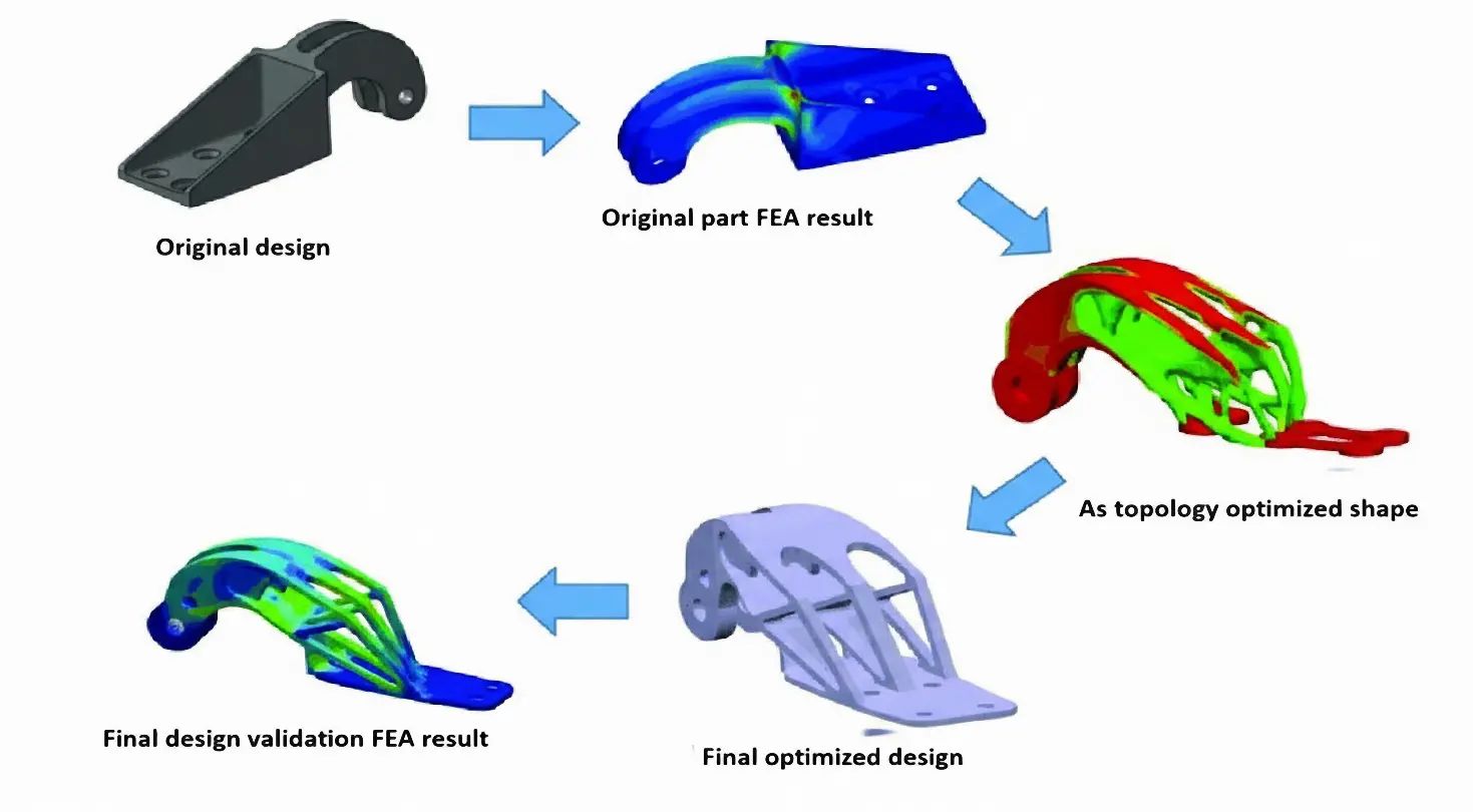
Drone weight remains a primary limiting factor in drone performance, directly influencing flight endurance, payload capability, energy consumption, and overall operational efficiency. Topology optimization provides an effective and systematic approach to mitigating this challenge by enabling substantial structural weight reduction while maintaining required stiffness, strength, and dynamic stability [10]. Topology optimization process shown in Figure 1 is a computational technique that optimizes the distribution of materials in structures to achieve specific performance goals (objective function), such as reducing weight while maintaining stiffness. To simplify the process, topology optimization simulations are usually divided into four main stages: preprocessing, topology optimization, postprocessing, and verification [13]. Topology optimization (TO) has emerged as a critical design tool for achieving lightweight and high-strength structures [14]. Based on numerical methods such as the Solid Isotropic Material with Penalization (SIMP) technique, TO removes unnecessary material from low-stress regions, leading to optimized geometries that retain stiffness while minimizing weight [15]. Bendsoe and Kikuchi (1988) and Rozvany and Zhou (1992) initially proposed the SIMP method. The SIMP method predicts an optimal material distribution within a given design space, for given load cases, boundary conditions, manufacturing constraints, and performance requirements. A reduction of an element’s material elastic modulus leads to a reduction of element stiffness. According to the SIMP method, the global stiffness is modulated according to [16]:
| $${K}_{\text{SIMP}}\left(\rho \right)={\sum }_{e=1}^{N}\left[{\rho }_{min}+\left(1-{\rho }_{min}\right){\rho }_{e}^{p}\right]{K}_{e}$$ | (1) |
where $${K}_{\text{SIMP}}\left(\rho \right)$$ is the global stiffness, $${K}_{e}$$ is the stiffness matrix of element $$e$$, $${\rho }_{e}$$ is the element density, p is the penalization factor, $${\rho }_{min}$$ is the minimum density parameter, and $$N$$ is the total number of elements.
A popular optimization objective is to maximize the overall stiffness of a structure, or minimize its compliance under a given amount of mass removal, which can be modulated by Equation (2) [17]:
| $$\underset{x}{\mathrm{min}}c\left(x\right)={U}^{T}K\left(x\right)U={\sum }_{e=1}^{N}{\left({x}_{e}\right)}^{p} {u}_{e}^{T}{k}_{0e}{u}_{e}$$ | (2) |
Subject to:
| ```latex\frac{V\left(x\right)}{{V}_{0}}=f,``` | |
| ```latexK\left(x\right)U=F,``` | |
| ```latex0<{x}_{min}\le {x}_{e}\le 1.``` |
where U and F are the global displacement and force vectors, respectively, K is the global stiffness matrix, ue and k0e are the element displacement vector and stiffness matrix, respectively, x is the vector of design variables, xmin is a vector of minimum relative densities (non-zero to avoid singularity), N (=nelx × nely) is the number of elements used to discretize the design domain, p is the penalization power (typically p = 3), V(x) and V0 is the material volume and design domain volume, respectively and f (volfrac) is the prescribed volume fraction. When applied to drone frames, TO contributes to longer flight duration, improved energy efficiency, and enhanced payload capacity [18]. Integration of TO with additive manufacturing enables direct fabrication of optimized geometries without additional tooling or machining, further supporting sustainable design principles [19].
Topology optimization process is widely used to reduce drone frame weight without affecting strength, stiffness, or flight stability. Most studies follow the same workflow: CAD, FEA to find low-stress material to remove, then validation against stress and deflection limits. Table 1 compiles key recent studies and compares their materials, tools, optimization goals, weight reductions, and findings, providing a benchmark for positioning and evaluating the current work.
Table 1. Recent Studies on Topology Optimization for Drone Frames.
|
References |
Material/Model |
Software/Method Used |
Optimization Focus |
Weight Reduction (%) |
Key Findings |
|---|---|---|---|---|---|
|
[21] |
- |
SolidWorks Simulation |
Mass reduction and structural efficiency |
91% |
Reduced mass from 1558.44 g to 134.74 g by eliminating non-critical regions while maintaining structural integrity. |
|
[18] |
Epoxy resin thermoset polymer reinforced with aramid fibers |
SolidWorks |
Weight reduction and load balance |
80% |
Achieved major mass reduction while maintaining a safety factor of 53, ensuring balance and stiffness. |
|
[22] |
ABS (Acrylonitrile Butadiene Styrene) |
SolidWorks Simulation |
Structural integrity and lightweight design |
30% |
Improved overall rigidity and minimized stress concentrations after optimization. |
|
[1] |
ABS quadcopter frame |
ANSYS Design Modeler |
Weight optimization and structural stiffness |
96% |
Reduced frame weight from 9035 g to 337 g, maintaining mechanical stability and stiffness. |
|
[23] |
PLA (Polylactic Acid) H-shaped quadcopter |
SolidWorks |
Weight optimization for flight control |
50% |
Achieved 50% mass reduction, improving control and flight performance at high altitude. |
|
[10] |
PLA quadcopter frame |
SolidWorks Simulation |
Topology optimization for weight reduction |
50% |
Achieved 50% reduction in frame mass while maintaining structural safety. |
|
[24] |
Nylon, ABS, and PLA (3D-printed frame) |
SolidWorks/Additive Manufacturing |
Material comparison and weight optimization |
50% |
Designed and printed frames in multiple materials, achieving lightweight structures. |
|
[25] |
Aluminium 2024-T3 and Carbon Composite T700S (Aircraft wing) |
Topology optimization analysis |
Material performance and mass comparison |
10% (Al), 9% (CC) |
Demonstrated effective mass reduction in aircraft wing design while preserving strength. |
The structural mass of drone frames significantly constrains payload capacity and flight endurance [8,9]; to address this challenge, this study aims to conduct topology optimization to achieve notable weight reduction in an eight-motor (The flat Octocopter) delivery drone while preserving structural and flight performance. Using simulation-driven topology optimization, the material can be strategically removed from regions with low stress and reinforced in high-stress regions, producing an optimized drone frame that could extend battery life by allowing a delivery drone to fly longer or carry more payload [26]. This work illustrated an end-to-end workflow that links parametric CAD modeling, SIMP-based topology optimization under flight-representative loading, geometry reconstruction for manufacturability, and Finite Element Analysis (FEA) validation using consistent load and boundary conditions, followed by Fused Deposition Modeling (FDM) fabrication and electronic component preparation for integration. The implementation of 3D printing technology has greatly facilitated the manufacturing process and allowed the rapid fabrication and testing of the optimized frame components [27].
2. Materials and Methods
The methodology of this study has focused on utilizing topology optimization to reduce the weight of the drone structure and ensure adequate mechanical strength and stability. The 3D model of the delivery drone frame has been designed using SOLIDWORKS 2025 software, and the material properties have been selected for drone fabrication, which is Polylactic Acid (PLA). To replicate realistic operating conditions and loading scenarios, such as payload forces and thrust forces, and fixed support constraints, a Finite Element Analysis (FEA) environment has been used. The topology optimization process has been conducted using the Solid Isotropic Material with Penalization (SIMP) technique, targeting the material minizine while maintaining the structural integrity. Following the optimization process, the Finite Element Analysis (FEA) has been implemented for the drone components to ensure both the stress and deformation of the drone components within the permissible limits of Polylactic Acid (PLA). 3D printing has been used to fabricate drone components using Fused Deposition Modeling (FDM). Eventually, the electronic components were selected and integrated into the Octocopter drone frame for delivery applications.
2.1. 3D Model of the Drone Frame
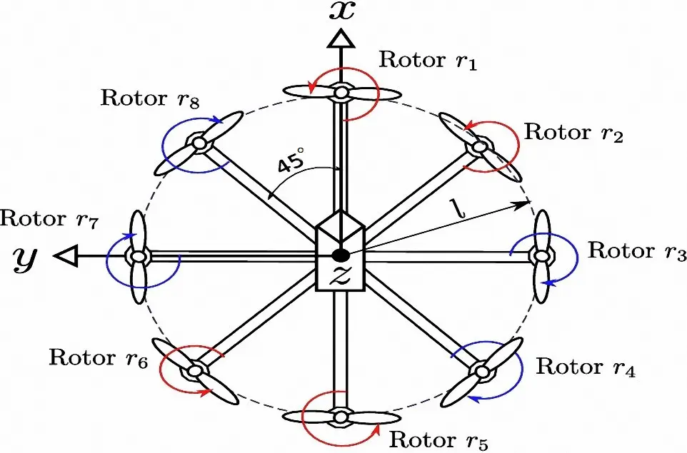
The Octocopter drone has been selected in this study over other multirotor drones, such as Quadcopter and Hexacopter, due to its ability to carry a higher payload, greater flight stability, and operational reliability, which are crucial factors for delivery drone applications. Their characteristics make the Octocopter drone ideal for professional, industrial, and logistics delivery missions, where safety, endurance, and performance are prioritized over cost considerations [28]. Generally, the Octocopter drone has two configurations or types, which are the Flat Octocopter and the Coaxial (X8) Octocopter [28,29]. The study focuses on the Flat Octocopter shown in Figure 2, which has several benefits over the Coaxial (X8) Octocopter, including a straightforward structural layout, efficient aerodynamics, and ease of maintenance for the drone. The Flat Octocopter design has many features, including eight rotors mounted symmetrically on each arm. And arms positioned 45 degrees apart around the drone’s center of gravity (CoG), forming a balanced 360-degree arrangement. The geometric symmetry ensures uniform thrust distribution, which enhances list efficiency, flight control, and manoeuvrability, which are critical factors in achieving precise and reliable performance for a delivery drone.
In this study, the Flat Octocopter drone has been designed, and it consists of several structural components, including the drone arms, bottom cover, middle and top covers, and leg brackets, as shown in Figure 3. Each component has a critical role in ensuring the mechanical integrity and functional integration of the system. These structural components provide the necessary mounting interfaces for the drone electronic components system such as the motors, flight controller, battery, and modules, thereby enabling precise alignment, load distribution, and vibration isolation during operation.
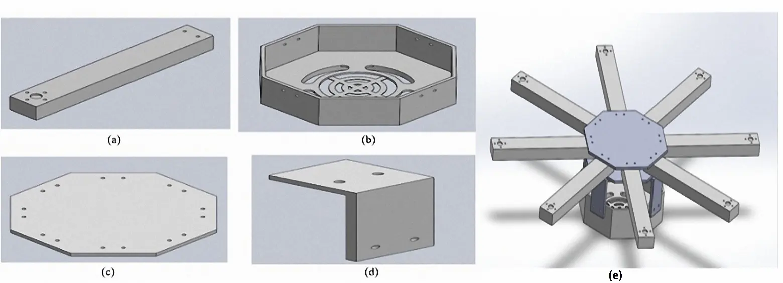
Figure 3. Drone Parts Before Optimization: (a) Drone Arm, (b) Bottom Cover, (c) Middle and Top Cover, (d) Leg Bracket, (e) Orignal Drone Frame.
Before applying topology optimisation, the mass of the original octocopter frame was quantified to establish a clear reference for evaluating weight savings. Each structural component was weighed and recorded, along with its quantity in the assembly, to identify the main contributors to the overall frame mass. Table 2 presents the initial weight breakdown of the drone parts and the total baseline weight used for subsequent comparisons.
Table 2. The Initial Weight of The Drone Parts.
|
Drone Parts |
Number of the Parts |
Initial Weight of the Parts |
|---|---|---|
|
Drone arm |
8 |
154.4 g |
|
Bottom cover |
1 |
163.6 g |
|
Middle cover |
1 |
67.3 g |
|
Top cover |
1 |
67.3 g |
|
Leg bracket |
4 |
14.2 g |
|
Total weight |
1590.2 g |
|
2.2. Material Selection
This study concentrates on the design and development of a lightweight octocopter frame designed for delivery applications, where structural efficiency and payload capacity are essential metrics for successful operations. Polylactic Acid (PLA) was chosen as the material for the drone frame since it is widely used in quick prototyping and functioning drone modelling, and its mechanical qualities are listed in Table 3. Which is the best choice since it is inexpensive [31], easy to print [32], and has a good strength-to-weight ratio, which makes it good for medium-sized drone. The material has a printing temperature range of 180–220 °C, which is not too high. This means that it can be made using regular consumer-grade fused deposition modelling (FDM) 3D printers without the need for extra hardware [33]. As well as it is an ideal choice for this study because it has moderate mechanical strength but is nevertheless stiff and stable enough for non-critical structural parts of delivery drones [34].
Table 3 lists the PLA material properties adopted in this study, including strength, stiffness, density, and Poisson’s ratio. These parameters were used to set up the finite element model and to evaluate whether stresses and deflections remain within acceptable limits for the selected filament.
2.3. Finite Element Analysis (FEA)
Finite Element Analysis (FEA) essential step in designing and optimizing of the delivery drone, which is enabling the engineers to simulate and evaluate the mechanical behavior of the critical components under the operational load, which is computational approach provides detailed insights about stress distribution, strain and deformation, to ensure the drone frame components satisfy with both safety and performance requirements essential for reliable delivery operations [35]. Equation (3) expresses the global finite element equation, the equilibrium relationship between the external nodal force vector $$\left[F\right]$$, the global stiffness matrix $$\left[K\right]$$, and the nodal displacement vector $$\left[U\right]$$:
| ```latex\left[F\right]=\left[K\right]\left[U\right]``` | (3) |
Here, the nodal displacements and rotations (the degrees of freedom contained in $$\left[U\right]$$ are the primary unknowns to be solved for. Prior to solving this system, the force vector $$\left[F\right]$$ must be assigned the known external loads, and the displacement vector $$\left[U\right]$$ must reflect any prescribed boundary conditions. Conducting it before topology optimization is a crucial step for validating the initial frame design, by identifying high stress regions and establishing targeted optimization objectives [36]. The numerical analysis was performed using the SOLIDWORKS Simulation, which is a robust platform for high precision structural analysis and performance evaluation. This integration into the topology optimization process is based on accurate and realistic computational data. This approach enhances the structural efficiency, weight-to-strength ratio, and operational reliability of Octocopter delivery drone, which can enhance the endurance and payload performance in real world delivery missions.
In the Finite Element Analysis (FEA) and topology optimization for the delivery drone frame, thrust force constitutes an essential parameter because it is inducts to governs the structural loads acting on the drone frame. By determining an accurate thrust force to represent the primary upward force generated by the prolusion system to counteract gravity and sustain flight. Thrust force conditions have been applied to simulate the aerodynamic and mechanical stresses experienced in reality during operating the drone, allowing for showing the high stress areas and potential failure zones with the drone frame. This method ensures the 3D model accurately reflects operational conditions encountered during the delivery missions. Thrust force plays a critical role in topology optimization, serving as a design constraint and guiding the redistribution of material in the design domain to achieve maximum stiffness and minimize weight. The designers are able to achieve the optimal mass distribution and reduce the material usage while enhancing the drone performance by increasing the payload capacity or the flight time. Determining the accurate thrust force not only ensures the reliability of the analysis, but also indicates that the results of the optimized frame achieve maximum efficiency, durability, and performance for the delivery drone under the flight conditions. The thrust force, also known as the motor force, is responsible for driving the drone upward. The following equation can determine the thrust force for each motor in Octocopter drone [24]:
Given the produced thrust, the corresponding power per motor is determined by Equation (5) [11]:
In this work, the thrust-to-weight ratio (TWR) of the delivery drone has been calculated at 2:1 indicating the total thrust force generated by the propulsion is twice the total weight of the drone frame. By choosing this ratio, the drone will be able to have stable flight, maneuverability, and energy efficiency, also, this ratio is considered to be a critical performance parameter in drone design. The thrust-to-ratio (TWR) of 2:1 allows the drone to have stable flight while using about 50% of the available battery power, which enables converting battery power and increasing the flight duration [37]. Equation (1) shows how thrust force, weight, and power consumption are related. It also revealed that only 50% of the total thrust force is able to counteract gravity when hovering. Maintaining this balance preserves a sufficient thrust force to support during the delivery’s missions. The total weight of the drone in this study has been calculated as 2518 g, including all the drone components and electronic components. Based on Equation (4), the thrust force has been determined for each motor as 629.5 g, which is approximately 6 N per motor. The thrust force has been applied as boundary conditions to show realistic and reliable structural performance simulations. The calculations [38] of thrust force for the drone can be further supported by the study of Shen CH, et al., which this work detailed the fundamental information on how propellers operate. The methods described in this journal, combined with electric motor simulations, allow for more accurate prediction of the thrust system and expected flight time. The combination of these methods ensures a robust theoretical base and reliable performance evaluation.
2.4. Topology Optimization
Using topology optimization to identify the most efficient material distribution within the design space. The integration between Finite Element Analysis (FEA) and topology optimization has the ability to select and remove unwanted materials while maintaining the structural integrity to withstand against operational loads. Topology optimization enhances the structural efficiency and aerodynamic performance of the drone by minimizing non-materials and also improves the thrust-to-weight ratio, which is a critical parameter influencing flight endurance and maneuverability. The main objective of topology optimization is to achieve minimum structural weight without compromising stiffness or strength, topology optimization not only reduces the drone frame weight but also improves flight dynamics, leading to greater energy efficiency and payload capacity. The SOLIDWORKS topology optimization module has been used to determine the optimal weight of the Octocopter drone frame. The topology optimization process involved retaining high stress and payload regions while removing material form low stress regions. The expected outcomes of conducting topology optimization for delivery drones are enhanced flight performance, energy efficiency, and operational reliability.
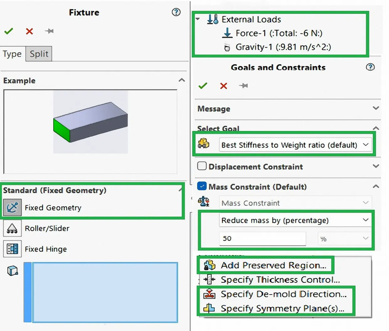
Figure 4 shows the settings of the topology optimization process, which illustrate the boundary conditions, loads, objectives, and constraints to achieve an optimized lightweight drone frame. The fixed geometry constraint has defined the boundary conditions by restricting motion at key attachment points, such as motor mounts and frame joints, to replicate realistic operational supports. The external loads have been applied, including a thrust force of 6 N per motor at the motor mounting locations to simulate lift and gravity (9.81 m/s2), ensuring accurate stress distribution under flight conditions. For goal and constraint settings, the topology optimization objective has been selected to achieve the best stiffness-to-weight ratio, with a 50% mass reduction constraint, allowing the removal of unwanted material while maintaining sufficient stiffness and structural integrity to improve the thrust-to-weight ratio and energy efficiency of the delivery drone. The manufacturing controls ensure that the final design remains for fabrication by defining preserved regions (motor mounts and screw holes), specifying the demold direction, and applying symmetry planes to maintain aerodynamic balance. Finally, the standard mech has been employed for the drone components, which provides a balanced compromise between computational efficiency and accuracy. These settings establish a comprehensive framework for topology optimization of a drone frame and produce a lightweight, high-performance delivery drone frame tailored for operational demands.
2.5. 3D Printing
In this study, the 3D printing method has been selected for the fabrication of drone components using Fused Deposition Modeling (FDM), an additive manufacturing technique that can print accurate components and is effective for processing thermoplastic polymers such as Polylactic Acid (PLA). Before conducting the fabrication process, the topology-optimized drone components have been validated using Finite Element Analysis (FEA) simulations to ensure all drone components are fabricated.
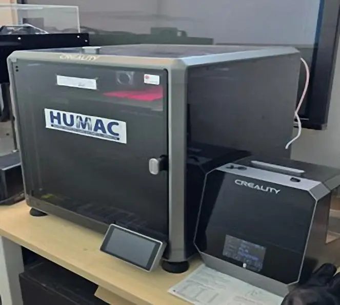
In this work, the Creality K1C 3D printer (Shenzhen Creality 3D Technology Co., Ltd., based in Shenzhen, China) form has been used to fabricate the drone components shown in Figure 5. This 3D printer has an enclosed printing environment to maintain consistent thermal conditions, which are critical to ensure the dimensional accuracy, print stability, and interlayer adhesion. To fabricate the PLA drone components, a 0.4 mm nozzle has been selected at a printing temperature of 220 °C; this parameter was selected to obtain detailed geometry and a high-quality surface. The 3D printing process used standardized parameters, including infill density, layer height, print speed, and build orientation. By utilizing this systematic approach, it was exhibited that the PLA drone components possessed high structural integrity and fabrication precision. Enable the drone frame for mechanical test and performance evaluation in the delivery drone design framework.
2.6. Electronic Components Selection
The electronic components required for the octocopter drone are listed in Table 4. The octocopter construction necessitated the careful selection and precise integration of several key electronic and mechanical subsystems.
Table 4. Components of a Drone.
|
No. |
Components |
Model |
|---|---|---|
|
1 |
Flight Controller |
Matek Systems H743-WING |
|
2 |
GPS Module |
Beitian BN-880 |
|
3 |
Electronic Speed Controller (ESC) |
Cyclone 20A BLHeli_S |
|
4 |
Motor |
- |
|
5 |
Propeller |
DJI-9450 |
|
6 |
Li–Po Battery |
XN Eagle 3S |
|
7 |
Radio Receiver |
FlySky FS-iA6B |
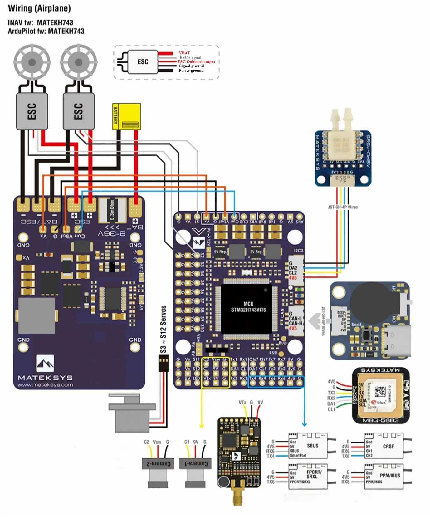
The drone’s structure is based on the flight controller (FC), which incorporates a Matek Systems H743-WING module as shown in the wiring diagram in Figure 6. The FC acts as the main processing unit, receiving control inputs and sensor data, and efficiently transferring power from the XN Eagle 3S LiPo battery to the propulsion system. Eight Cyclone 20A BLHeli_S Electronic Speed Controllers (ESCs) are directly connected to the FC’s power outputs and the FC’s control signal pins. The ESCs, in turn, regulate the power supplied to the eight DC brushless motors (BLDC), dictating the RPM of the DJI-9450 self-tightening propellers to achieve the necessary thrust and attitude control. Each motor and ESC pair is attached to one of the eight drone arms. The navigation and control systems are connected to the FC via digital and analog communication links. The Beitian BN-880 GNSS module, which provides precise GPS and magnetometer data for position and heading, is connected to the FC’s serial port. Wireless command and control are established through the FlySky FS-iA6B Receiver, which is connected to the FC and receives signals from the ground-based transmitter.
Circuit Connection of Components
Table 5 indicates the summary of the connections between the pins of the drone components. The efficient functioning of the octocopter depends on a linked electrical system. Every peripheral device, such as the electronic speed controllers (ESCs), GPS unit, and Radio Receiver (RX), is attached by soldering onto their assigned pins on the circuit boards. A key aspect of the circuit layout involves linking all parts to both the power supply (VCC) and ground to guarantee a power flow and a shared reference voltage. Robust cables and gold-plated connectors ensure critical connections between the eight ESCs and their respective low-voltage direct current (BLDC) motors, with low contact resistance and reliable power transfer under high-current loads. The entire system is ultimately powered by a lithium-polymer battery (Bat), which is connected to the power controller (FC) for comprehensive power distribution.
Table 5. Connections between Components.
|
FC |
ESC |
GPS |
RX |
Bat |
|---|---|---|---|---|
|
RX2 |
- |
- |
B/VCC |
- |
|
TX4 |
- |
RX |
- |
- |
|
RX4 |
- |
TX |
- |
- |
|
5V |
- |
VCC |
CH6 |
- |
|
GND |
- |
GND |
CH5 |
- |
|
SCL |
- |
SCL |
- |
- |
|
SDA |
- |
SDA |
- |
- |
|
VCC |
ESC1-8 VCC |
- |
- |
VCC |
|
GND |
ESC1-8 GND |
- |
- |
GND |
|
S1 |
ESC1 |
- |
- |
- |
|
S2 |
ESC2 |
- |
- |
- |
|
S3 |
ESC3 |
- |
- |
- |
|
S4 |
ESC4 |
- |
- |
- |
|
S5 |
ESC5 |
- |
- |
- |
|
S6 |
ESC6 |
- |
- |
- |
|
S7 |
ESC7 |
- |
- |
- |
|
S8 |
ESC8 |
- |
- |
- |
3. Results and Discussion
The computational topology optimization progress is illustrated in Figure 7 and Figure 8 for a practical drone frame design. The preliminary topology optimization results shown in Figure 7 demonstrate how material is distributed according to stress and load paths. However, the geometry at this stage remains irregular and difficult to fabricate the design. The refinement and optimization geometries shown in Figure 8 indicate smooth geometry, structural efficiency, and a 3D printable design model. These designs preserve the essential payload capacity regions identified during the topology optimization settings and remove excess material to reduce the overall drone weight.
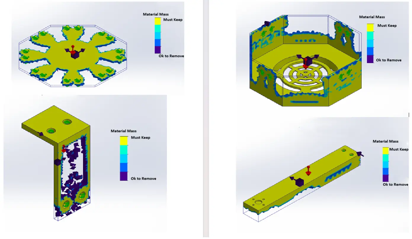
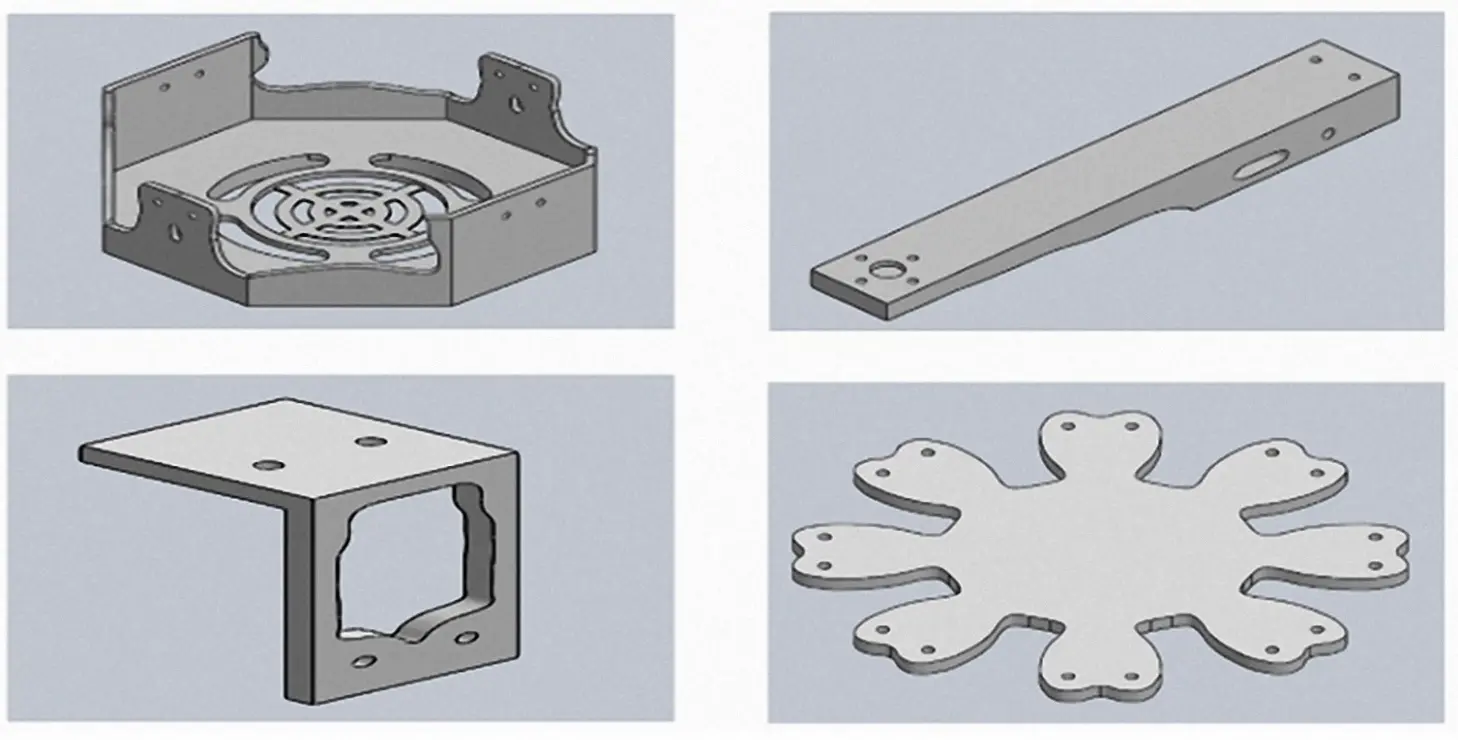
Table 6 shows the results of the topology optimization for the drone and demonstrates the difference between the original and optimized drone frame weight. Through an iterative process combining structural analysis and topology optimization, an optimal, lightweight drone has been achieved without compromising mechanical integrity. The mechanical properties of Polylactic Acid (PLA) have been considered to maintain the design within the allowable limits for both stress and deformation, which are 49.5 [40] MPa and 4.7 mm [41] respectively, to ensure the drone’s operation safety and durability. The topology optimization results have achieved a 37.3% weight reduction in the total mass of the original drone frame, showing the effectiveness of the topology optimization process in reducing the materials usage while maintaining stiffness and strength. The mass reduction (from 1590.2 g to 997.1g) is a direct result of SIMP technology, a structural optimization technique based on stiffness. Under the influence of gravity and applied thrust loads (approximately 6 N per motor), the optimizer gradually removes material from areas of low stress level (areas that contribute minimally to overall stiffness), while preserving material along the main load paths that bear the bending and torsional loads between the motor mounting brackets, arm joints, and bottom cover. The results have confirmed that the combination of topology optimization and structural analysis successfully enhanced the drone’s structural efficiency and thrust-to-weight ratio, making it suitable for high-demand delivery applications.
Table 6. The Total Mass of The Original Frame and The Final Optimized Frame.
|
Property |
Original Frame |
Optimized Frame |
|---|---|---|
|
Mass (g) |
1590.2 g |
997.1 g |
|
Percentage of reduction (%) |
37.3% |
|
3.1. Validation of the Optimized Drone Frame Through Finite Element Analysis (FEA)
A Finite Element Analysis (FEA) has been conducted to validate the optimized drone components under realistic operating conditions, ensuring the reliability and safety of the drone frame. The analysis has been performed using the same loading and boundary conditions as the topology optimization. Figure 9, Figure 10, Figure 11 and Figure 12 show the validation results and confirmed both the maximum stress and deformation within the allowable limits of Polylactic Acid (PLA). These validation results ensure the optimized drone frame has adequate strength, stiffness, and stability, demonstrating that the drone can safely endure operational loads during flight without issues.
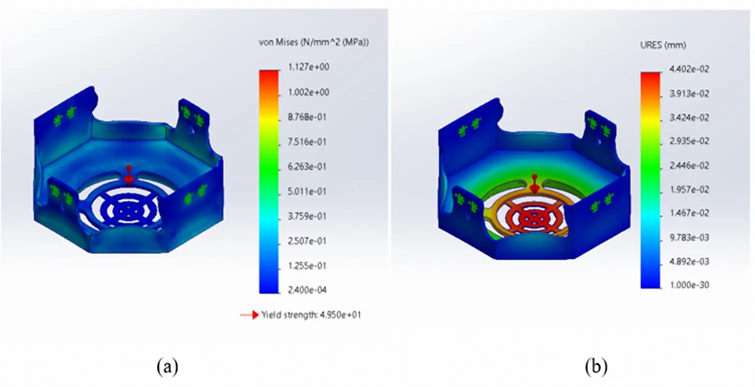
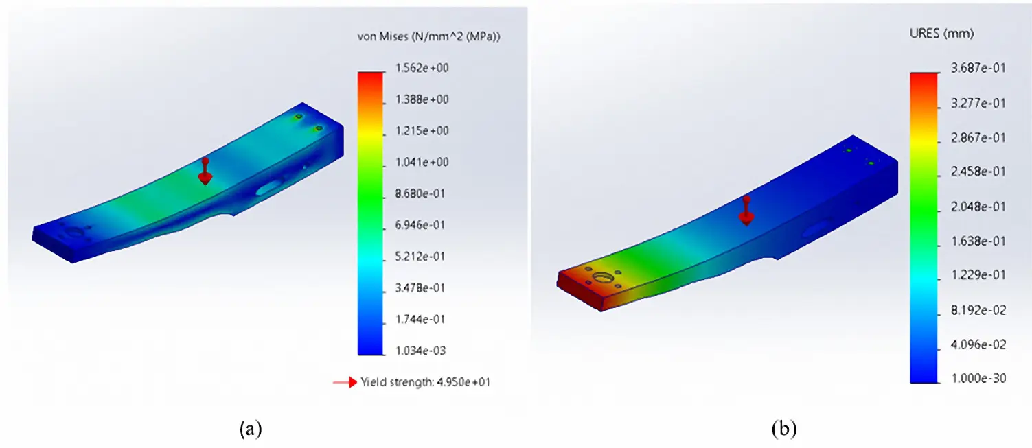
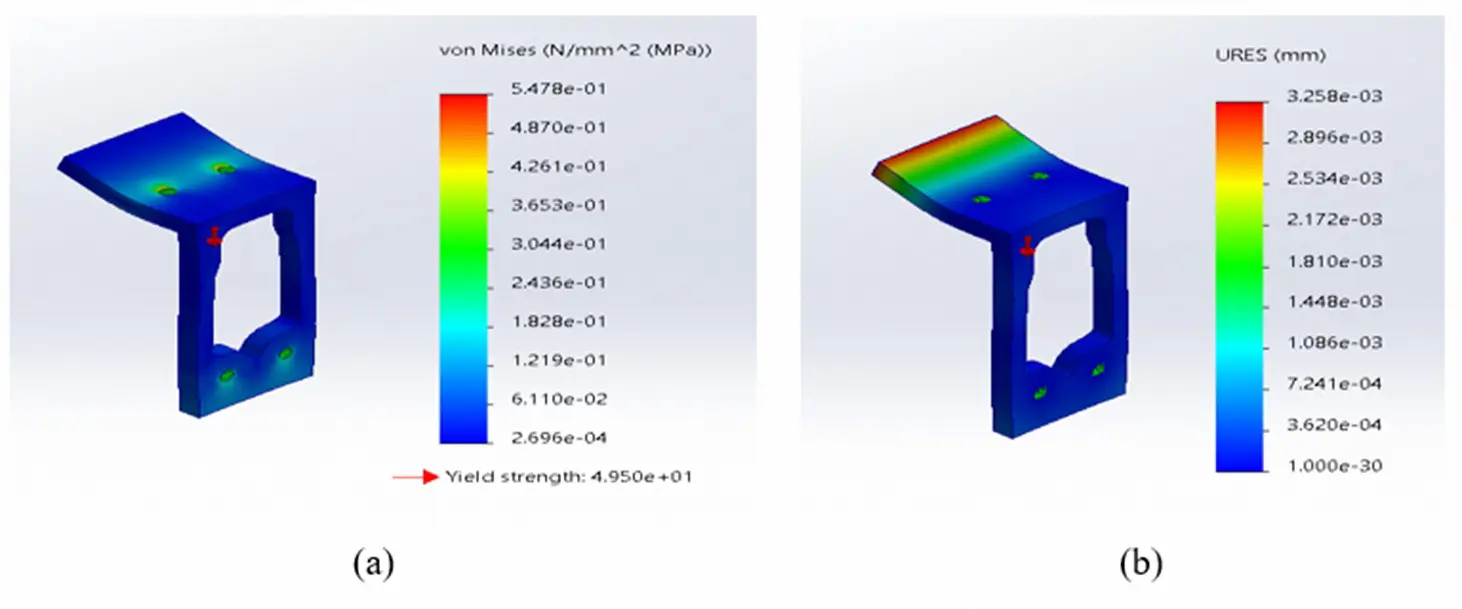
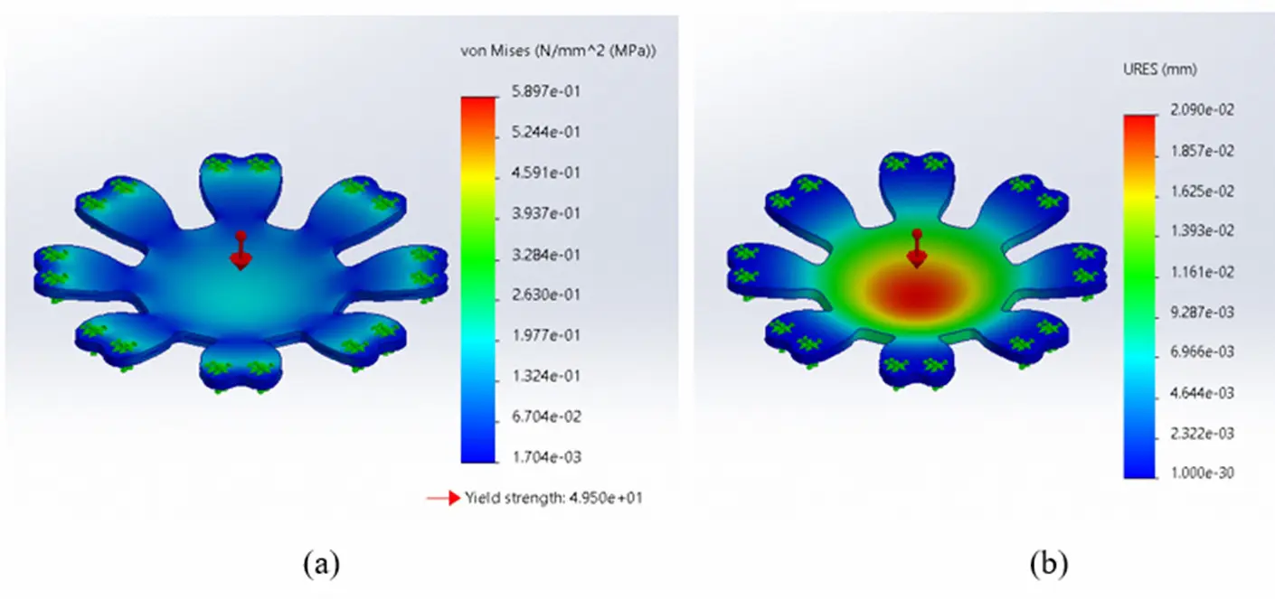
The validation results for the primary drone frame components are shown in Table 7, including the bottom cover, drone arms, top and middle covers, and leg brackets. Each of these components has been analyzed using the verified mechanical properties of. Polylactic Acid (PLA) under realistic operational conditions to evaluate the drone frame stiffness, stability, and overall performance. The outcomes demonstrate that the optimized drone frame components are safely withstanding the applied life forces and payload capacity stresses without compromising the structural integrity. The results illustrate that the optimized drone frame possesses the structural stiffness and reliability necessary to support all critical flight phases, including take-off, hovering, and landing, thereby confirming the effectiveness of the topology optimization and validation process through Finite Element Analysis (FEA).
Table 7. Finite Element Analysis (FEA) Validation Results for the Optimized Drone Components.
|
Property |
PLA-Allowable Limit |
Bottom Cover |
Drone Arm |
Leg Bracket |
Middle and Top Cover |
|---|---|---|---|---|---|
|
Maximum stress (MPa) |
49.5 |
1.127 |
1.562 |
5.478 × 10⁻¹ |
5.897 × 10⁻¹ |
|
Maximum deformation (mm) |
4.7 |
4.402 × 10⁻² |
3.687 × 10⁻¹ |
3.258 × 10⁻³ |
2.09 × 10⁻² |
3.2. Additive Manufacturing of the Optimized Octocopter Frame
The delivery drone frame has been fabricated using Fused Deposition Modeling (FDM) 3D printing under optimized processing conditions, as shown in Figure 13. The drone frame has been printed at a nozzle temperature of 220 °C, and the nozzle diameter is 0.4 mm. The printing process demonstrated smooth filament extrusion, strong interlayer, adhesion, and high-quality surface finish. The material demonstrated excellent bed adhesion at a bed temperature of 50 °C, the printing process was done successfully without any noticeable warping or detachment. The printing process is insulting in a dimensionally stable and structurally reliable drone frame suitable for further evaluation and testing.
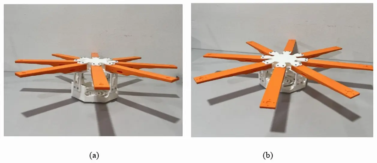
Figure 13. 3D Printed the Optimize Drone Frame (a) 45-degree form side view (b) 80 degree from side view.
Table 8 shows the compression in the time of the 3D printing process for the delivery drone frame before and after conducting the topology optimization method, which indicates a clear improvement in fabrication efficiency. The total printing time has been decreased from 24.04 h to 18.59 h, demonstrating that the optimized drone frame requires less production time. The drone frame components, including the bottom cover, drone arm, leg bracket, and top and middle covers, have experienced reduced printing time, demonstrating the benefits of removing unnecessary materials and simplifying geometry through topology optimization. The reduction in printing time not only speeds up the fabrication process but also lowers material consumption and energy use during the printing process. These outcomes, which show a decrease in printing time, demonstrate that topology optimization enhanced the manufacturability of the PLA drone frame by making the fabrication process faster and more efficient while still preserving its structural and functional requirements.
Table 8. Printing Time.
|
Drone Parts |
Drone Frame Before Topology Optimization |
Drone Frame After Topology Optimization |
|---|---|---|
|
Drone arm |
4.24 h |
4.01 h |
|
Bottom cover |
13.18 h |
10.08 h |
|
Middle and Top cover |
5.32 h |
3.13 h |
|
Leg bracket |
1.30 h |
1.17 h |
|
Total Weight |
24.04 h |
18.59 h |
4. Limitations and Future Work
This work is limited by being simulation-only and primarily static-structural, so it does not yet capture key real-world multirotor effects such as propulsion-induced vibration and modal behavior (natural frequency shifts/resonance), dynamic/transient events (landing shock/impact), and cyclic fatigue loading that can drive failure at motor mounts, joints, and arm-to-body interfaces; it also ignores Multiphysics influences (thermal/environmental impacts on PLA stiffness/damping) and does not fully represent FDM-PLA anisotropy, defects, and process variability. Future work will therefore extend validation through experimental mechanical testing of printed parts, modal/vibration characterization (including tap/impact correlation), fatigue assessment via analysis and cyclic bending/torsion tests focused on critical interfaces, and more realistic dynamic, impact, and coupled Multiphysics simulations (and aero–structural coupling where relevant), with material/model calibration to the actual printed PLA behavior. The prototype material (FDM-PLA) is currently suitable for rapid prototyping and low-cost fabrication, yet its long-term functionality may be constrained by environmental exposure. PLA is relatively low in terms of glass-translation temperature (60 °C), and as such, high ambient temperatures and solar heating can minimize stiffness and enhance creep risk; further, PLA degradation is aggravated by moisture and temperature (hydrolysis), and polymer structure and mechanical behavior will change with time under UV radiation.
5. Conclusions
This work demonstrates the combination of topology optimization, Finite Element Analysis (FEA), and 3D printing to enhance the structural performance of a Polylactic Acid (PLA) flat octocopter frame for delivery missions. By utilizing SOLIDWORKS simulation and the Solid Isotropic Material with Penalization (SIMP) method, the drone frame achieves 37.3% weight reduction in total weight, form 1590.2 g to 997.1 g, with compromising the structural integrity. By obtaining this reduction, the thrust-to-weight ratio and the payload capacity, or the flight time of the drone. The validation results have confirmed that all the critical regions of the drone operate within the allowable stress and deformation limits of Polylactic Acid (PLA) material, which are 49.5 MPa and 4.7 mm, respectively, indicating the optimized drone frame can safely withstand lift and payload capacity during the flight without facing any issues or failure. The topology optimized drone frame also contributed to reducing the total time of the 3D printing process form 24.04 h to 18.59 h. This integration between topology optimization and the 3D printing workflow produced a lightweight drone frame, structurally stiff and quicker to manufacture, which increases payload capacity and reduces energy consumption during the delivery flight. These results highlight topology optimization as a practical design approach for multirotor frames and provide a starting point for future work on alternative materials, multi-objective optimization, and full system-level testing.
Statement of the Use of Generative AI and AI-Assisted Technologies in the Writing Process
During the preparation of this manuscript, the author(s) used ChatGPT and Gemini in order to language editing, idea structuring and grammar checking. After using this tools, the author(s) reviewed and edited the content as needed and take full responsibility for the content of the published article.
Acknowledgments
We would like to acknowledge Simon Anandaraj Doss, Seerla Kanagarajoo, and Chew Zhe Zhi for their valuable assistance with 3D printing.
Author Contributions
Conceptualization, H.O.Y.O. and H.S.C.; Methodology, H.O.Y.O. and J.T.; Software, H.O.Y.O., M.A.A.A. and J.T.; Validation, H.S.C., H.O.Y.O. and A.O.M.; Formal Analysis, H.O.Y.O. and J.T.; Investigation, H.S.C. and H.O.Y.O.; Resources, N.R.R.R.; Data Curation, H.O.Y.O. and M.A.A.A.; Writing—Original Draft Preparation, H.O.Y.O. and J.T.; Writing—Review & Editing, H.S.C. and A.O.M.; Visualization, H.O.Y.O. and H.S.C.; Supervision, N.R.R.R., H.S.C. and K.M.Y.; Project Administration, H.O.Y.O. and H.S.C.; Funding Acquisition, H.S.C.
Ethics Statement
Not applicable.
Informed Consent Statement
Not applicable.
Data Availability Statement
Data available from the corresponding author on request.
Funding
This work was supported by the University of Wollongong Malaysia, Postgraduate and Research Centre (PGRC), based in Utropolis Glenmarie, Malaysia and Sunway University Postgraduate Studentship.
Declaration of Competing Interest
The authors declare that they have no known competing financial interests or personal relationships that could have appeared to influence the work reported in this paper.
References
- Nvss S, Esakki B, Yang LJ, Udayagiri C, Vepa KS. Design and Development of Unibody Quadcopter Structure Using Optimization and Additive Manufacturing Techniques. Designs 2022, 6, 8. DOI:10.3390/designs6010008 [Google Scholar]
- Mahmoodi A, Hashemi L, Laliberte J, Sajadi SM. Optimizing energy and CO2 efficiency in last-mile delivery using hybrid fleet models. Sustain. Futures 2025, 10, 101089. DOI:10.1016/j.sftr.2025.101089 [Google Scholar]
- MohamedZain AO, Hou LW, Chua H, Yap K, Boon LK. The Design and Fabrication of Multiple-Transmitter Coils and Single-Receiver Coils for a Wireless Power Transfer System to Charge a 3s LiPo Drone’s Battery. Energies 2023, 16, 3629. DOI:10.3390/en16093629 [Google Scholar]
- Telli K, Kraa O, Himeur Y, Ouamane A, Boumehraz M, Atalla S, et al. A Comprehensive Review of Recent Research Trends on Unmanned Aerial Vehicles (UAVs). Systems 2023, 11, 400. DOI:10.3390/systems11080400 [Google Scholar]
- Iqab M. Harnessing Drones for Faster, Cheaper, and Greener Logistic Solutions in Challenging Environments. 2024. Available online: https://www.theseus.fi/handle/10024/853861 (accessed on 10 October 2025).
- Farrag TA, Askr H, Elhosseini MA, Hassanien AE, Farag MA. Intelligent Parcel Delivery Scheduling Using Truck-Drones to Cut down Time and Cost. Drones 2024, 8, 477. DOI:10.3390/drones8090477 [Google Scholar]
- Millar RC, Laliberté J, Mahmoodi A, Hashemi L, Meyer RW. Designing an Uncrewed Aircraft Systems Control Model for an Air-to-Ground Collaborative System. SAE Int. J. Aerosp. 2024, 17, 225–241. DOI:10.4271/01-17-02-0014 [Google Scholar]
- Hassanalian M, Rice D, Abdelkefi A. Evolution of space drones for planetary exploration: A review. Prog. Aerosp. Sci. 2018, 97, 61–105. DOI:10.1016/j.paerosci.2018.01.003 [Google Scholar]
- Mahmoodi A, Hashemi L, Laliberte J. Framework for truck—RPAS hybrid models in last-mile delivery. Drone Syst. Appl. 2025, 13, 1–32. DOI:10.1139/dsa-2024-0068 [Google Scholar]
- Al-Haddad LA, Jaber AA, Giernacki W, Khan ZH, Ali KM, Tawafik MA, et al. Quadcopter Unmanned Aerial Vehicle Structural Design Using an Integrated Approach of Topology Optimization and Additive Manufacturing. Designs 2024, 8, 58. DOI:10.3390/designs8030058 [Google Scholar]
- Shelare S, Belkhode P, Nikam KC, Yelamasetti B, Gajbhiye T. A payload-based detail study on design and simulation of hexacopter drone. Int. J. Interact. Des. Manuf. (IJIDeM) 2024, 18, 2675–2692. DOI:10.1007/s12008-023-01269-w [Google Scholar]
- Tonoy AAR. Integrating SolidWorks and Python in Robotic System Design: Advancements in. TechRxiv 2025. DOI:10.36227/techrxiv.175459445.50275080/v1 [Google Scholar]
- Aguirre Guerrero D, Jacobs G, Zerwas T, Delgadillo A. Integrating topology optimization into model-Based systems engineering for lightweight structural design. Forsch. Im Ingenieurwesen/Eng. Res. 2025, 89, 63. DOI:10.1007/s10010-025-00829-8 [Google Scholar]
- Cao Y, Zhang Q, Zhang S, Tian Y, Dong X, Song X, et al. Optimization of Rock-Cutting Tools: Improvements in Structural Design and Process Efficiency. Computation 2025, 13, 152. DOI:10.3390/computation13070152 [Google Scholar]
- Rozvany G. The SIMP method in topology optimization—Theoretical background, advantages and new applications. In Proceedings of the 8th Symposium on Multidisciplinary Analysis and Optimization, Long Beach, CA, USA, 6–8 September 2000. DOI:10.2514/6.2000-4738 [Google Scholar]
- Holdy M, Beniak J. Topological optimization processes. Glob. J. Eng. Technol. Adv. 2022, 10, 94–99. DOI:10.30574/gjeta.2022.10.1.0023 [Google Scholar]
- Sigmund O. A 99 line topology optimization code written in Matlab. Struct. Multidiscip. Optim. 2014, 21, 120–127. DOI:10.1007/s001580050176 [Google Scholar]
- Martinez Leon AS, Rukavitsyn AN, Jatsun SF. UAV Airframe Topology Optimization. In International Conference on Industrial Engineering; Springer: Cham, Switzerland, 2021; pp. 338–346. DOI:10.1007/978-3-030-54814-8_41 [Google Scholar]
- Ranjan R, Samant R, Anand S. Integration of Design for Manufacturing Methods with Topology Optimization in Additive Manufacturing. J. Manuf. Sci. Eng. 2017, 139, 061007. DOI:10.1115/1.4035216 [Google Scholar]
- Gebisa AW, Lemu HG. A case study on topology optimized design for additive manufacturing. IOP Conf. Ser. Mater. Sci. Eng. 2017, 276, 012026. DOI:10.1088/1757-899X/276/1/012026 [Google Scholar]
- Asif SH, Hasan K, Dhar NR. Topology optimization and 3D printing of a unibody quadcopter airframe. IOP Conf. Ser. Mater. Sci. Eng. 2024, 1305, 012021. DOI:10.1088/1757-899x/1305/1/012021 [Google Scholar]
- Bay B, Eryıldız M. Design and Analysis of a Topology-Optimized Quadcopter Drone Frame. Gazi Üniversitesi Fen Bilimleri Dergisi Part C Tasarım ve Teknoloji 2024, 12, 427–437. DOI:10.29109/gujsc.1316791 [Google Scholar]
- Ali KM, Tawafik MA, Jaber AA. Quadcopter Topology Optimization Based on Impact Analysis. AIP Conf. Proc. 2023, 2977, 030022. DOI:10.1063/5.0182388 [Google Scholar]
- Balayan A, Mallick R, Dwivedi S, Saxena S, Haorongbam B, Sharma A. Optimal Design of Quadcopter Chassis Using Generative Design and Lightweight Materials to Advance Precision Agriculture. Machines 2024, 12, 187. DOI:10.3390/machines12030187 [Google Scholar]
- Arshad A, Murali A, Kaidalovs T, Gavrilovs P. Computational investigations for topology optimization of UAV and small-scale aircraft wings. Arch. Mech. Eng. 2024, 71, 167–188. DOI:10.24425/ame.2024.150563 [Google Scholar]
- Uthayasurian P, MohamedZain AO, Betharajoo SK, Chua HS, Yap K. SolidWorks-based topology optimization for octocopter design and development. IET Conf. Proc. 2023, 2023, 100–108. DOI:10.1049/icp.2023.1767 [Google Scholar]
- Yemle S, Durgude Y, Kondhalkar G, Pol K. Design & Analysis of Multi-Frame for Octo & Quad Copter Drones. Int. Res. J. Eng. Technol. 2019, 6, 2935–2939. [Google Scholar]
- Niemiec R, Gandhi F. Multi-rotor Coordinate Transforms for Orthogonal Primary and Redundant Control Modes for Regular Hexacopters and Octocopters. In Proceedings of the 42nd Annual European Rotorcraft Forum, Lille, France, 5–8 September 2016. [Google Scholar]
- Chen H, Quan F, Fang L, Zhang S. Aerial grasping with a lightweight manipulator based on multi-objective optimization and visual compensation. Sensors 2019, 19, 4253. DOI:10.3390/s19194253 [Google Scholar]
- Salazar JC, Sanjuan A, Nejjari F, Sarrate R. Health-aware control of an octorotor UAV system based on actuator reliability. In Proceedings of the 2017 4th International Conference on Control, Decision and Information Technologies (CoDIT), Barcelona, Spain, 5–7 April 2017; pp. 815–820. DOI:10.1109/CoDIT.2017.8102695 [Google Scholar]
- Madhavan Nampoothiri K, Nair NR, John RP. An overview of the recent developments in polylactide (PLA) research. Bioresour. Technol. 2010, 101, 8493–8501. DOI:10.1016/j.biortech.2010.05.092 [Google Scholar]
- Joseph TM, Kallingal A, Suresh AM, Mahapatra DK, Hasanin MS, Haponiuk J, et al. 3D printing of polylactic acid: Recent advances and opportunities. Int. J. Adv. Manuf. Technol. 2023, 125, 1015–1035. DOI:10.1007/s00170-022-10795-y [Google Scholar]
- Coppola B, Cappetti N, Di Maio L, Scarfato P, Incarnato L. 3D printing of PLA/clay nanocomposites: Influence of printing temperature on printed samples properties. Materials 2018, 11, 1947. DOI:10.3390/ma11101947 [Google Scholar]
- Trivedi AK, Gupta MK, Singh H. PLA based biocomposites for sustainable products: A review. Adv. Ind. Eng. Polym. Res. 2023, 6, 382–395. DOI:10.1016/j.aiepr.2023.02.002 [Google Scholar]
- Brischetto S, Torre R. Preliminary finite element analysis and flight simulations of a modular drone built through fused filament fabrication. J. Compos. Sci. 2021, 5, 293. DOI:10.3390/jcs5110293 [Google Scholar]
- Chang CL, Chen CS, Huang CH, Hsu ML. Finite element analysis of the dental implant using a topology optimization method. Med. Eng. Phys. 2012, 34, 999–1008. DOI:10.1016/j.medengphy.2012.06.004 [Google Scholar]
- Abidali A, Agha SA, Munjiza A, Shaheed MH. Development of a solar powered multirotor micro aerial vehicle. Sci. Rep. 2024, 14, 5771. DOI:10.1038/s41598-024-54079-9 [Google Scholar]
- Shen CH, Albert FYC, Ang CK, Teck DJ, Chan KP. Theoretical development and study of takeoff constraint thrust equation for a drone. In Proceedings of the 2017 IEEE 15th Student Conference on Research and Development (SCOReD), Wilayah Persekutuan Putrajaya, Malaysia, 13–14 December 2017; pp. 18–22. DOI:10.1109/SCORED.2017.8305428 [Google Scholar]
- MATEKSYS. Available online: https://www.unmannedtechshop.co.uk/products/matek-h743-wing-v3-ardupilot-flight-controller?srsltid=AfmBOopKVde5AVjvI4gl-QQa2j7fsrm4XPxc67aSQcSzJwfmCF2KsRwo (accessed on 21 November 2025).
- Li M, Xu Y, Fang J. Orthotropic mechanical properties of PLA materials fabricated by fused deposition modeling. Thin-Walled Struct. 2024, 199, 111800. DOI:10.1016/j.tws.2024.111800 [Google Scholar]
- MohamedZain AO, Chua H, Yap K, Uthayasurian P, Jiehan T. Novel Drone Design Using an Optimization Software with 3D Model, Simulation, and Fabrication in Drone Systems Research. Drones 2022, 6, 97. DOI:10.3390/drones6040097 [Google Scholar]