Milling Mechanism of Sheet Fiberglass Plastic by a Tungsten Carbide Tool with Diamond and Diamond-like Wear-Resistant Coatings

Milling Mechanism of Sheet Fiberglass Plastic by a Tungsten Carbide Tool with Diamond and Diamond-like Wear-Resistant Coatings
Sergey V. Fedorov
1,*
 Evgeny E. Ashkinazi
2
Mikhail P. Kozochkin
1
Artem A. Ershov
1
Artem P. Litvinov
2
Enver S. Mustafaev
1
Sergey N. Grigoriev
1
Vitaly I. Konov
2
Evgeny E. Ashkinazi
2
Mikhail P. Kozochkin
1
Artem A. Ershov
1
Artem P. Litvinov
2
Enver S. Mustafaev
1
Sergey N. Grigoriev
1
Vitaly I. Konov
2
Received: 30 December 2025 Revised: 08 January 2026 Accepted: 16 January 2026 Published: 21 January 2026

© 2026 The authors. This is an open access article under the Creative Commons Attribution 4.0 International License (https://creativecommons.org/licenses/by/4.0/).
1. Introduction
In recent years, the production and consumption of polymer composites containing carbon or glass fibers in an epoxy matrix or polyester resin have been rapidly increasing. This growth is expected to continue in various industries, particularly in the automotive sector, due to the exciting mechanical properties combined with a relatively low cost [1]. Layered plastics can undergo all types of machining that are used for manufacturing metal parts. However, in most cases, products made of such composite materials require a special approach to machining, which is significantly different due to the anisotropic and heterogeneous composite structure and the effects of plastic deformation [2]. In addition, it is necessary to consider the influence of manufacturing technology on the mechanism of chip formation, which is also not insignificant when determining optimal cutting modes, since, unlike metals, layered plastics have 200 times lower thermal conductivity [3]. However, the use of cooling fluids is generally not recommended, as it can cause swelling and negatively impact the electrical and mechanical properties of most layered plastics. Based on the results [4], it was ascertained that spindle speed significantly affects cutting temperature and fine particle emission, while cutting force, specific cutting energy, and tool wear are influenced by feed rate. Application of cooled air or the use of a small amount of lubricating nanofluids during machining [5] can help solve the problem to some extent, but it is not always effective, and overcooling can lead to cracking.
Much attention is being paid to hybrid processing methods, such as laser processing, ultrasonic vibrations, and abrasive water jets, which have the potential to improve surface integrity and reduce cutting tool wear. Additionally, there is the possibility of using multi-purpose processing, which can affect the fibers orientation [6]. The effectiveness of this technology has been experimentally analyzed and compared with the results of conventional edge milling [7]. Edges processed using multi-axis trimming technology were significantly better in quality than edges processed using conventional technology, thanks to the choice of the correct cutter angle. It was suggested that a hybrid strategy, such as rapid roughing with trochoidal cutters followed by conventional finishing, could improve productivity, accuracy, and tool life [8,9]. From the perspective of multi-energy fields, methods such as low-temperature cold air, magnetic fields, and ultrasonic vibration can effectively enhance processing performance [10].
It becomes apparent that there is a need for additional analysis of the factors that affect the accuracy of processing and the quality of the processed surface, which are influenced by both the wear characteristics of the tools and the machinability of layered composites such as fiberglass, which accounts for 95% of the international market and is prone to peel-up and push-down delamination, uncut fibers, fiber pull-out, tearing, borehole damage, surface cavities, burrs, sub-surface damage, and glass transition [11,12].
Despite lower cutting force requirements, fiberglass composites have a significant impact on cutting tool wear, as the abrasive properties of the material lead to rapid tool wear [13]. Sun et al. [14] also noted that abrasive wear of the tool during fiberglass processing is caused by the presence of fiber-based solid particles in fiberglass blanks. At the same time, adhesive wear may be present, resulting from heating during cutting, and chips may form on the cutting edge. Occurring under significant cutting loads. An increase in the feed rate, which has a minimal effect on the cutter wear, which is mainly due to the abrasive wear of the tool on the flank surface, dramatically increases the likelihood of fiberglass delamination [15], which takes into account the fact that the filler fibers do not deform significantly with the polymer matrix due to the significant difference in the elastic moduli of the components [16]. In some cases, the delamination coefficient is calculated as the ratio of the average delamination load to the sample width [17].
The practice of fiberglass cutting with various tools has shown that in dry machining, the tool material has a significantly greater effect on surface quality than the tool geometry, which determines cutting force, the number of failures, and the nature of chip removal. For example, Dabhade S. [18] noted that using a carbide tool results in a lower roughness value compared to high-speed steel. Ducobu et al. [19] conducted a comparative analysis of various PCD and carbide cutting tool geometries for composite material milling. The results of this study show that the diamond tool is the best option, combining less delamination and lower cutting forces, resulting in the best performance compared to carbide tools. However, the total cutting force for the carbide tool can be significantly reduced by using mills with more teeth, effectively reducing the feed per tooth. However, the wear resistance of a PCD tool is much higher than that of a carbide tool, making it more cost-effective despite its higher price. At the same time, Zawada-Michałowska et al. shown that the surface quality obtained using a carbide tool with a PCD coating was higher than when using a tool with PCD inserts during the milling process with the same technological parameters [20].
Knap et al. investigated the effect of various wear-resistant coatings, both traditional CrN-type nitrides and DLC-based carbon coatings, on the processing quality of fiberglass [21]. It was noted that the surface treated with mills with a CrN type coating showed a poor cut, manifested in the uneven protruding fiber form and surface damage, and the best results were obtained when using a DLC tool for all studied roughness parameters. The durability of such a tool can be increased by combining the best properties of modern nitride nanocomposite coating (CrAlSi)N with an antifriction DLC surface layer [22]. The use of a PCD-coated carbide tool is promising [23]. It can be deposited using various technologies [24] directly on the working surface of arbitrary-geometry carbide mills and allows for the production of tools that utilize the best properties of diamond, such as high hardness and thermal conductivity, excellent resistance to abrasion, and a low coefficient of friction. These tools exhibit the lowest level of wear, although they may not always provide the best roughness.
In the mechanical cutting process, the surface defects of the workpiece are an important indicator of cutting quality and also reflect the condition of both the machine tool and the cutting tool [25]. The review of factors affecting the quality of layered composites processing shows that it is complicated to assess the degree of influence of each factor on the defect’s formation on the processed surfaces, especially since the orientation of the composite fibers on different surfaces of the processed part will vary significantly [26]. It is evident that we need to monitor the milling process, which allows us to observe the cutting process kinetics in real time and compare the current diagnostic signals parameters with the results of surface analysis. The use of acoustic monitoring promises to be an option for monitoring during processing. The use of this method in mechanical tests may contribute to a greater knowledge of composite materials, as well as determine the stresses [27]. Of course, monitoring the temperature in the chip formation zone and the power parameters would also be beneficial. However, it is challenging to monitor temperature changes at the cutting edge, especially above 130 °C and during dielectric processing. Additionally, monitoring power parameters based on changes in drive power is only suitable for modes where the power consumption is significantly higher than the idle power consumption, which is not the case in our application. Under these conditions, the use of acoustic emission (AE) signals for monitoring the processing of layered composites becomes the only diagnostic method [28] in media, including solid media, as a result of perturbations caused by a wide range of factors [29].
The purpose and novelty of this work is a comparative study of the machinability of a glass-fiber-based composite when milling with tungsten carbide end mills with carbon-based wear-resistant coatings obtained using various technologies: diamond and DLC coatings deposited on an intermediate layer of a composite nanocrystalline coating based on (TiCrAlSi)N.
2. Materials and Methods
2.1. Processed Material
The workpieces were chosen to be plates of FR4 TG 135 foiled fiberпglass-reinforced plastic, 140 × 25 × 1.6 mm in size. FR4 is a material consisting of glass fibers that are impregnated with an epoxy resin of an electrical grade. It is mainly used in electrical engineering because of its high electrical insulation properties. The degree of this material’s moisture absorption is relatively low, making it suitable for use in high humidity conditions. FR4 has high strength, but it is easily machined with standard tools. The main properties of the composite are listed in Table 1.
Table 1. Basic properties of FR4 TG 135 fiberglass.
|
Parameter |
Value |
|---|---|
|
Thickness |
1.6 mm |
|
Density |
1.4 g/cm3 |
|
Destructive stress in compression perpendicular to the layers |
200 MPa |
|
Tensile strength |
69 MPa |
|
Glass transition |
135 °C |
2.2. The Machine and Tools
For machining, in particular, milling, FR4 requires tools that can withstand the abrasive effects of this composite material. Typically, tungsten carbide end mills are used to ensure their durability. The material has a relatively low moisture absorption rate, which allows limited use of coolants; we did not use them in our experiments.
End mills were used for milling operations. Table 2 provides detailed information about the tool used in this study. The tools were made on a machine, the Walter Helitronic Micro (Walter AG, Tubingen, Germany), from calibrated rods made of a 6% Co content CTS12D alloy with a submicron grain (0.4–0.8 µm), specially designed for diamond coating (Ceratizit, Reutte, Austria). The milling was carried out on a DMC 635 V ecoline machine (DMG MORI AG, Bielefeld, Germany) (Figure 1) without coolant in accordance with the mode shown in Table 3.
The processed fiberglass plate was clamped with two bolts in a specially milled groove. The plate could bend under the influence of the cutting force component Fy due to the low modulus of elasticity of fiberglass, which could affect the processing accuracy. The deflection value was measured using a profile-meter DektakXTL (Bruker, Billerica, MA, USA). In addition, the roughness parameters RA and RZ, as well as the waviness parameters: the average absolute value of the profile deviations from the middle line WA, and the height of the irregularities, which is determined by the sum of the maximum deviation from the middle line in 5 peaks and 5 valleys WZ were measured on each of the seven 20-mm sections.
Table 2. The end mills’ technical characteristics.
|
Parameter |
Value |
|---|---|
|
Diameter, D |
11.99 mm |
|
Number of teeth, z |
4 |
|
The rake corner, γ |
4.29° |
|
The flank corner, α |
7.29° |
|
Spiral angle, ω |
33.97° |
|
Flank surface width |
1.3 mm |
|
Cutting part length |
12 mm |
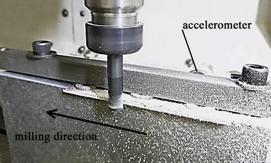
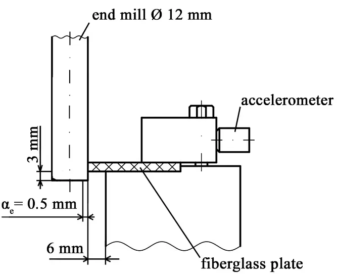
Table 3. Milling modes.
|
Parameter |
Value |
|---|---|
|
Cutting speed, V m/min |
115, 180, 230, 300 |
|
Rotation frequency, n min−1 |
3000, 4750, 6000, 8000 |
|
Feeding on the tooth, fz mm |
0.15, 0.075 |
|
Cutting depth, ap mm |
1.6 |
|
Cutting width, ae mm |
0.5 |
2.3. Deposition of Diamond-like and Diamond Carbon Films to End Mills
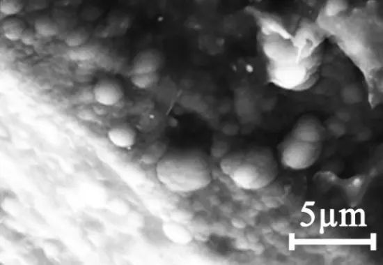
The diamond-like coating (DLC) C:H-Si was applied by CVD not directly to the surface of the carbide tool, but to an intermediate layer of the nitride coating (TiCrAlSi)N [30]. The Si content in the diamond-like coating was 0.8%. The coating was deposited using the Platit π311 + DLC unit (Platit, Selzach, Switzerland). The nitride inner layer was applied at a 500 °C temperature, a working gas pressure of 0.4 Pa, and a bias voltage of 50 V for an hour. The DLC technology involved reducing the process temperature to 180 °C. The deposition process of the outer coating layer was in a glow discharge in acetylene with the addition of 1% tetramethyl silane (CH3)4Si (TMS) at a pressure of P = 0.8 Pa and a bias voltage of 500 V for one hour and 40 min. The total coating thickness was 3.8 μm, with a DLC layer thickness of 0.7 μm (Figure 2a). The SEM image of the coating was obtained using a Vega 3 instrument (Tescan, Brno, Czech Republic).
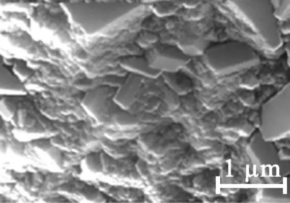
The diamond coating was deposited using a microwave plasma chemical reactor ARDIS 100 (Optosystems LLC, 5 kW, 2.45 GHz, Troitsk, Russia) [31]. The technology of applying such a coating is quite complex and multi-stage [32]. Prior to the experiment, the experimental mill’s surface was chemically etched with Murakami reagents (K3Fe(CN)6:KOH:H2O = 1:1:10) for 10 min and then with Karo acid (aqueous solution of H2SO4 and H2O2) for 4 s to reduce the concentration of cobalt on the tool surface, which can cause graphitization of the diamond film. For the same purpose and to reduce the level of residual thermal stresses in the next stage, a tungsten barrier layer was deposited on the etched tool using magnetron sputtering to form a layer up to 0.6 µm thick, followed by a 10-min process of diamond seed particle deposition, which ensured the reliable formation of diamond nuclei [33]. The diamond film growth occurred from a CH4/H2 gas mixture with a CH4 4% concentration at a substrate temperature of 850 °C. By periodically introducing nitrogen, a multilayer polycrystalline diamond structure was formed, which provides the necessary nanocrystal growth while reducing the overall surface coating roughness. The deposition process lasted for 6 h, and the thickness of the diamond film was 9–11 µm. These multilayer diamond coatings demonstrated better adhesion and abrasion resistance compared to single-layer diamond coatings [34]. Based on the above, a diamond coating was grown on the tool, consisting of six alternating layers of 1.9–2.1 μm microcrystalline grains in the shape of a parallelepiped or octahedron, and nanocrystalline grains about 80 nm in size [35] (Figure 2b).
It should be noted that, on the uncoated mills, the radius of the cutting-edge rounding was about 8 µm, as measured using the multifunctional optical measuring system MikroCAD premium+ (GFM, Teltow, Germany). The surface roughness on the uncoated and DLC mills was RA = 0.44 µm. The diamond coating increased the roughness to 2 µm, and the radius of rounding of the cutting-edge increased to 15–18 µm. The DLC technology also increased the cutting edge radius to 15 μm, mainly due to the nitride sublayer applied under the carbon coating.
2.4. Vibroacoustic Monitoring
Acoustic emission (AE) signals were recorded using an AP2037-100 piezoelectric accelerometer (Globaltest, Sarov, Russia). Table 4 presents its main technical specifications. The accelerometer was mounted on a fixture for securing the workpieces being processed (Figure 1) using a magnet. The vibration acceleration signals were recorded at a 200 kHz frequency.
Table 4. Technical specifications of the AP2037-100 accelerometer.
|
Conversion Factor |
10 |
mV/m/s2 |
|---|---|---|
|
Linear frequency range |
0.5...15,000 |
Hz |
|
Maximum impact (peak value) |
10,000 |
g |
|
Frequency of the installation resonance in the axial direction (more than) |
45 |
kHz |
|
Noise level, RMS [1 Hz ÷ 10 kHz] (less than) |
0.0035 |
m/s2 |
To ensure collection and processing of the accelerometer signals, a fast-acting external I/O module on the USB 2.0 analog-digital conversion E20-10 (LCard, Moscow, Russia) bus with a 10 MHz sampling frequency was used. The main technical specifications of the module are given in Table 5.
Table 5. Technical specifications of the E20-10 module.
|
Parameter |
Value |
|---|---|
|
ADC bit rate |
14 bits |
|
ADC conversion maximum frequency |
10 MHz |
|
Voltage measurement subranges (independent setting for each channel) |
±3.0 V; ±1.0 V; ±0.3 V |
|
Lower bandwidth frequency of the conversion path |
0 Hz |
|
Typical value of the upper frequency of the conversion path at 3 dB level |
1.2 MHz |
|
Typical signal-to-noise ratio of the ADC channel |
73 dB |
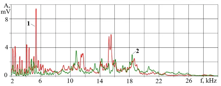
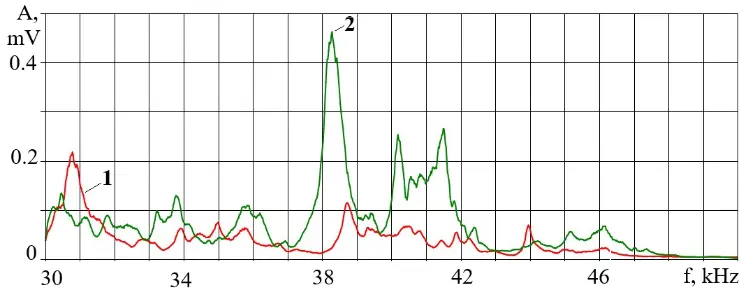
Acoustic information of the fiberglass plates processing was collected in three formats: the change in root mean square (RMS), AE amplitude in the low-frequency and high-frequency ranges, and the ratio of RMS amplitudes in these ranges (Kf). To select the most sensitive ranges, amplitude spectra of AE signals were first constructed, and the informative sections were selected based on the most significant change in signal amplitudes. As a result of the analysis of the AE signal spectra during the processing of identical workpieces with mills with different coatings and in different modes, two frequency ranges were selected: 0.2–20 kHz and 33–48 kHz, where the AE amplitudes were recorded, and the Kf ratio of the signal amplitudes in the low- and high-frequency ranges was calculated. Figure 3 shows examples of the joint AE spectra during the processing of a fiberglass plastic workpiece by mills with and without diamond coating.
The Kf parameter characterizes the power density (the ratio of the transmitted power to the area of impact), which decreases with wear of the cutting tool, with a decrease in the dynamic stiffness of the technological system, with a decrease in the cutting speed, or with the creation of other conditions affecting the chip separation process [36]. All of this leads to the AE signals being formed by longer voltage pulses, and the amplitudes in the low-frequency and high-frequency ranges ratio increases due to amplitude spectrum distortion. To increase the informativeness of Kf, it is necessary to select frequency ranges in the AE signal spectrum where the amplitude reacts more sharply to changes in cutting conditions, and where the influence of interference from the operating machine components is less. This effect is enhanced by selecting frequency ranges as far apart as possible on the frequency scale, but within the vibration sensor sensitivity range.
 |
|
(a) |
 |
|
(b) |
Figure 3. AE spectra during processing of textolite with uncoated (1) and diamond-coated (2) cutters (cutting speed 180 m/min, feed 0.15 mm/tooth): (a)—2–30 kHz range, (b)—30–50 kHz range.
In the cutting process, stress pulses occur not only during the separation of chip elements but also during the contact surfaces’ friction, under the influence of moving machine tools, and due to inhomogeneities in the structure of the processed material. Nevertheless, changes in the power density transferred from the tool to the workpiece affect the AE spectrum and can serve as an indicator of the quality of the cutting process.
In the present work, the tool wear due to the short cutting time did not affect the Kf change. However, changes in the cutting modes and properties of mills with different coatings affected the nature of the vibrations accompanying the cutting process. It is also important to note the specific compliance of the workpieces themselves: thin plates have low dynamic stiffness in the direction perpendicular to the cutting direction. At the same time, the plates clamping force, possibly unevenness along their length, could make their stiffness variable along the pass length, which inevitably affects the AE parameters.
They should be described with sufficient detail to allow others to replicate and build on published results. New methods and protocols should be described in detail, while well-established methods can be briefly described and appropriately cited. Give the name and version of any software used, and make clear whether the computer code used is available. Include any pre-registration codes.
3. Results and Discussion
Unfortunately, there may be unforeseen consequences when processing composite materials. As a rule, such materials are brittle, not plastic. Most composites can absorb energy only through damage and elastic deformation mechanisms, not through plastic deformation [37]. In this case, sensitivity to the rate of deformation plays an important role [38]. The results showed [39] that transverse cracking of the matrix is the first type of damage, followed by delamination between layers and longitudinal cracking of the matrix in fiber bundles. In particular, the strength of the fiber bundle itself has a greater effect on compression failure, which is the main reason for the final destruction of the material. A sharp decrease in the residual compressive strength and an even smaller decrease in the tensile strength as a result of impact damage characteristic of intermittent cutting are the main problems when assigning processing modes.
Substantial surface roughness is one of the most serious defects that can occur as a machining result of composite materials, and to expand the scope of application of glass fiber, precise milling is necessary to remove excess material [40]. However, the correlation of the surface roughness criteria, widely used in literature, to the mechanical behavior raises several contradictions [41]. In addition, the accuracy of dimensions and quality of surfaces processed by milling is sensitive to the temperature generated in the cutting zone exceeding cause melting or damage to the polymer matrix and, as a result, the formation of resin deposits on the cutting edge of the tool [42,43].
Research results show that the fiber being cut orientation angle has the most significant effect on surface roughness [44]. An et al. showed that when milling 90° orientation fibers, tool life is higher than when the 0° orientation, due to the fiber bending and increased friction between the fiber and the tool. Due to their nature, glass fibers break by a brittle fracture. The rupture of the fibers was perpendicular to or at an angle to the longitudinal axis. The average lengths of destroyed glass fibers ranged from 30 to 60 µm [45]. The FR4 fiberglass structure is characterized by the presence of fiberglass cloth with multidirectional fiber orientation. Consequently, during milling, several chip removal mechanisms will be present simultaneously [46], and the chip morphology will be discontinuous and broken. For fiber orientation close to 90°, shear fractures will be characteristic, and for fiber orientation close to 0°, fractures associated with fiber bending along the fiber-matrix interface will be characteristic. This is where the properties of carbon-based wear-resistant coatings, such as the extremely low (up to 0.14) coefficient of friction for DLC [47], and the high hardness and thermal conductivity of diamond polycrystalline coatings (up to 1400 W/(m*K)) [48], can be helpful.
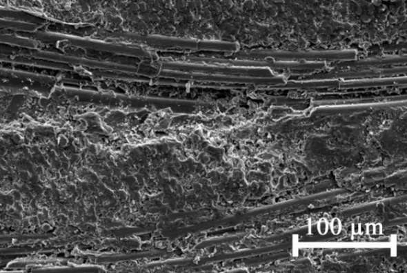
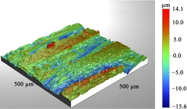
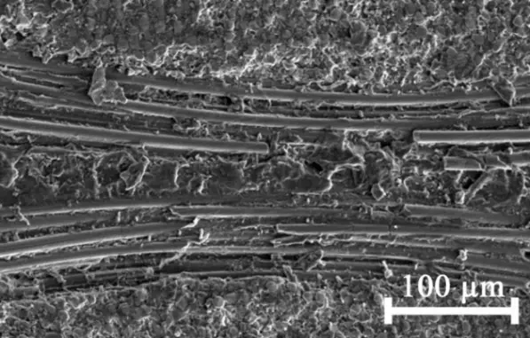
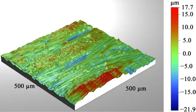
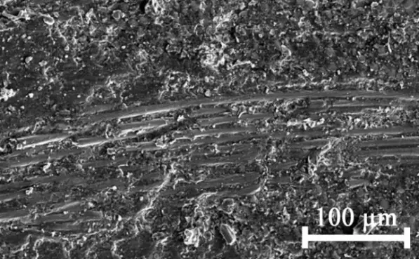
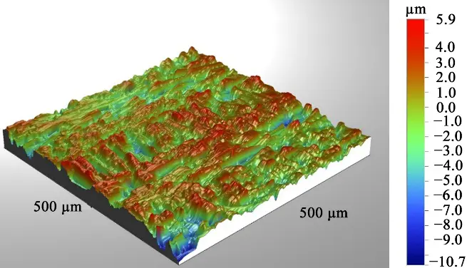
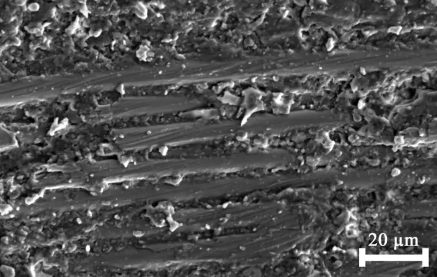
Figure 4 shows SEM images and 3D profile fiberglass reinforced plastic surface graphs after processing with different mills in the following mode: cutting speed V = 230 m/min, feed per tooth fz = 0.15 mm.
It can be seen that the surface roughness treated with end mills is affected by the tool interaction with the fiberglass, which is located at a slight angle to the cutting direction. For example, when processing with an uncoated mill (Figure 4a), it is possible to see the areas of composite failure between the fiber bundles and the epoxy matrix. The mill captures the fiber, bends it, and breaks it off in bundles, creating depressions that are clearly visible in the 3D profile. The mechanism of fiberglass fracture by a DLC milling cutter is similar, with the difference that the length of the fractured fiber sections is noticeably shorter due to its bending (Figure 4b). It can be assumed that the fracture zone between the matrix and the fiberglass will be smaller due to reduced friction. The 3D profile shows areas with intact and partially fractured fibers.
The fiberglass cutting mechanism with a diamond-coated mill is significantly different. The glass fiber is worn down due to the diamond grains in the coating high abrasive effect. In (Figure 4c) and (Figure 4d), it is easy to see the characteristic scratches on the worn-down sections of the fiber, rather than the broken-off sections. There is no evidence of composite failure between the matrix and the fiber. The 3D profile shows no individual fibers.
Research has shown that when milling fiberglass composites with end mills, cutting speed [45], feed rate [49], and axial depth are parameters that affect tool wear as much as the effect associated with different fiber orientations. In this case, increasing the feed rate increased the cutting force and surface roughness. Increasing the cutting speed also increased the cutting force but reduced surface roughness. However, this effect is non-linear [18], as at specific feed rates and high spindle speeds, there may be an increase in temperature at the tool-workpiece interface due to increased friction, which can sometimes lead to increased roughness and affect the final size of the product due to the accumulation of epoxy binder on the cutter working surface. In such cases, burnt black chips may even appear during machining.
 |
 |
|
(a) |
|
 |
 |
|
(b) |
|
 |
 |
|
(c) |
|
 |
|
|
(d) |
|
Figure 4. The surface of the fiberglass board after milling in the following mode: cutting speed V = 230 m/min, feed per tooth fz = 0.15 mm: (a)—uncoated milling cutter, (b)—DLC milling cutter, (c,d)—diamond-coated milling cutter.
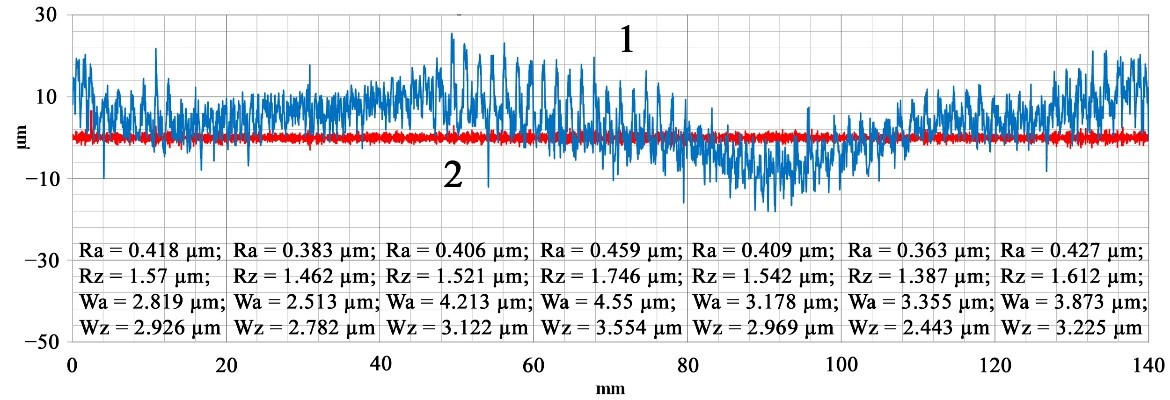
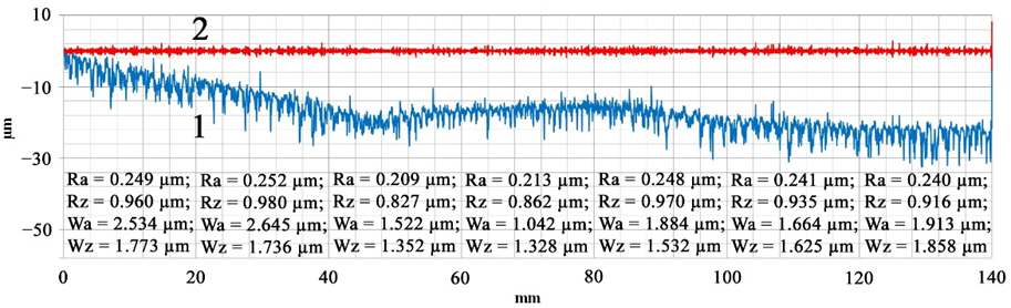
Figure 5 shows the profiles of the milled end surfaces of sheet fiberglass plastic using an end mill without a wear-resistant coating at various cutting and feed rates.
 |
|
(a) |
 |
|
(b) |
 |
|
(c) |
 |
|
(d) |
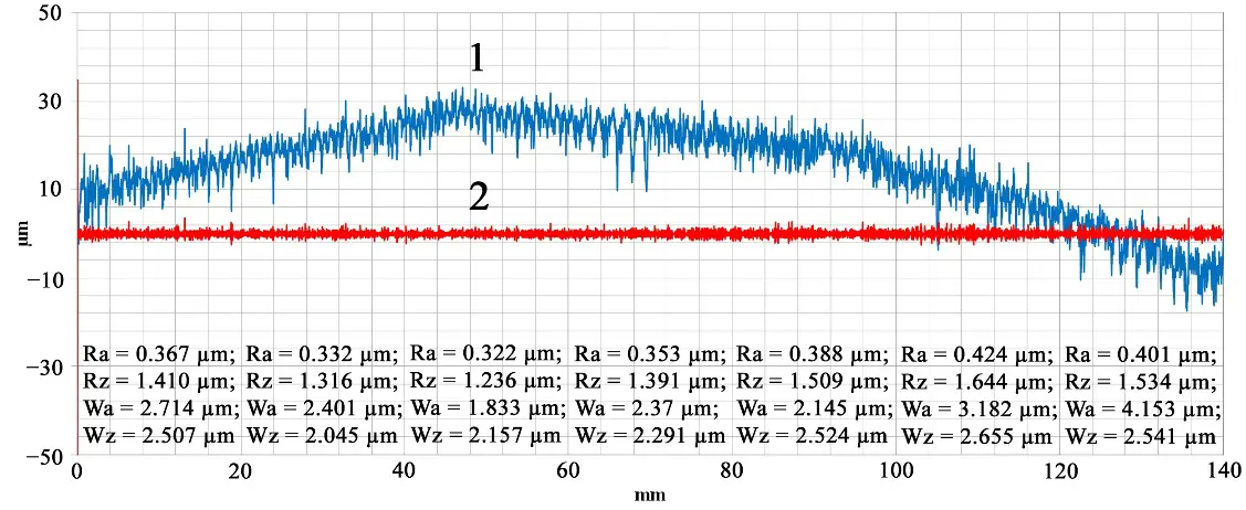
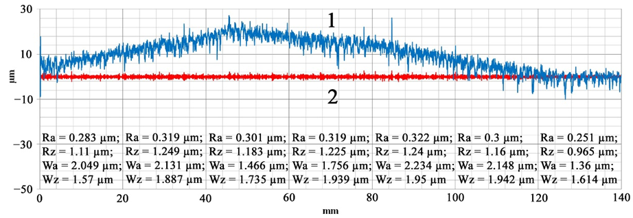
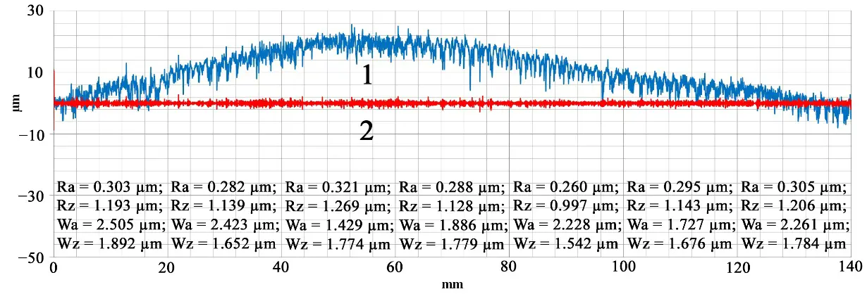
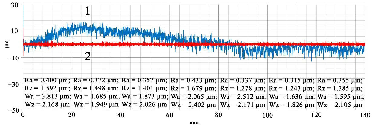
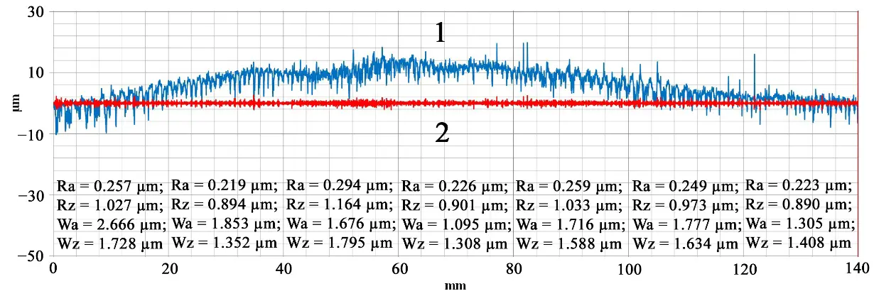
Figure 5. Profiles of the end surface (1) of FR4 fiberglass and its quality parameters (2 (RA)) after milling with an uncoated tool in the following modes: (a) cutting speed V = 115 m/min, feed fz = 0.15 mm/tooth, (b) cutting speed V = 180 m/min, feed fz = 0.15 mm/tooth, (c) cutting speed V = 230 m/min, feed fz = 0.15 mm/tooth, (d) cutting speed V = 230 m/min, feed fz = 0.075 mm/tooth.
When milling at a 115 m/min speed and a feed of fz = 0.15 mm/tooth, the cutting is unstable (Figure 5a). The profile shows that the fourth of the 20 mm sections has a buildup on the milling cutter, which caused the epoxy binder to heat up above its glass transition point. This buildup on the fifth of the 20 mm sections deformed the softened plastic, resulting in a loss of approximately 10 μm in size. In the sixth section, the adhesive apparently came off, and the cutting stability was somewhat restored. The average RA roughness value was 0.4 μm, and the height of the irregularities, determined by the maximum deviation from the WZ average line, was 2.97 μm.
Increasing the cutting speed to 180 m/min (Figure 5b) reduces the interaction time between the tool and the workpiece and improves heat dissipation. The cutting becomes stable, but under the influence of the cutting force component Fy, the fiberglass elastically deflects up to 50 μm, which is reflected as a hump on the profile. RA decreases to 0.34 μm, and WZ decreases to 2.6 μm. A further increase in cutting speed on the second and third 20 mm cuts (Figure 5c) reduces roughness to 0.26 μm and WZ to 1.7 μm, but the increased friction raises the temperature in the cutting zone. The fiberglass loses its elasticity, and the binder begins to the cutting-edge stick, resulting in a loss of size up to 20 μm.
Çelik et al. [13] noted that the best surface quality is achieved at low feed rates and high cutting speeds. In our case, the opposite is true, at least when processing FR4 fiberglass with uncoated end mills with the geometry shown in Table 2. Reducing the feed rate to 0.075 mm/tine results in a size loss of up to 30 μm, although the roughness values of RA = 0.23 μm and WZ = 1.5 μm become significantly lower (Figure 5d), but this reduction appears to be due to the heated plastic deformation.
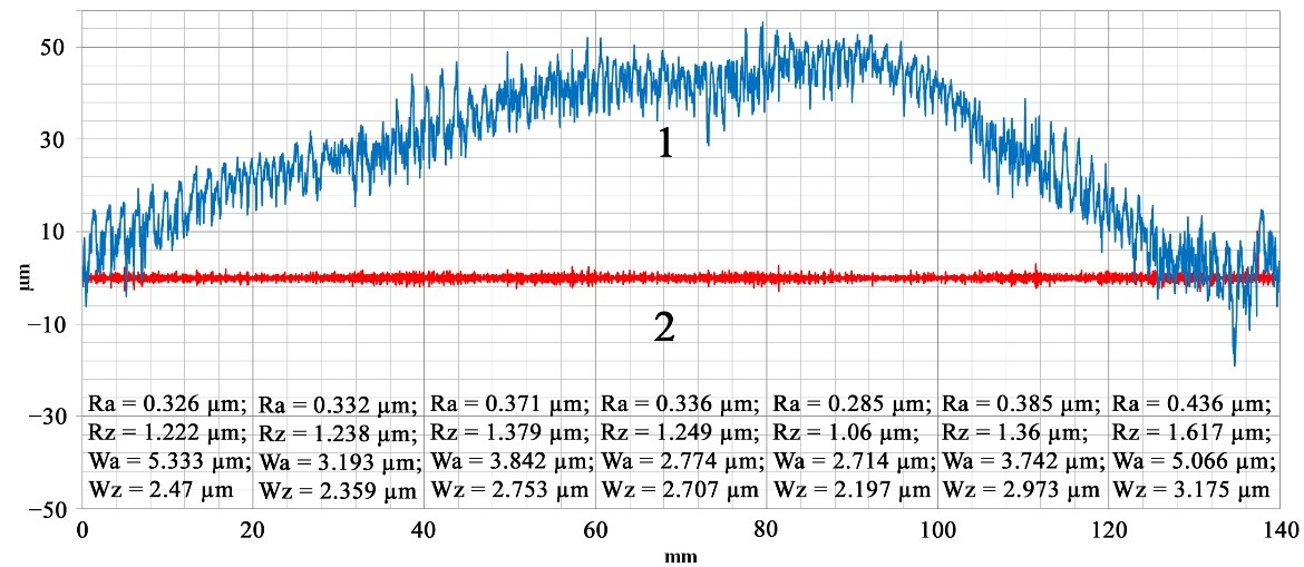
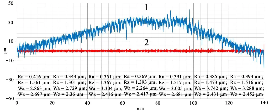
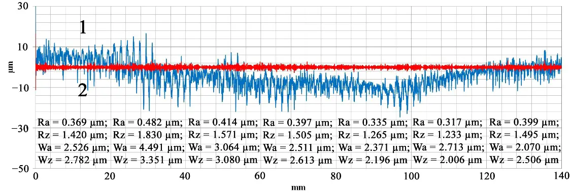
A DLC mill differs from a mill without coating not only by its low-friction coefficient, which reduces the heat load in the cutting zone, but also by its larger cutting-edge radius. Figure 6 shows the profiles of the end surface of a fiberglass plate after processing with this tool.
 |
|
(a) |
 |
|
(b) |
 |
|
(c) |
 |
|
(d) |
 |
|
(e) |
 |
|
(f) |
Figure 6. Profiles of the end surface (1) of FR4 fiberglass and its quality parameters (2 (RA)) after milling with a DLC tool in the following modes: (a) cutting speed V = 115 m/min, feed fz = 0.15 mm/tooth, (b) cutting speed V = 180 m/min, feed fz = 0.15 mm/tooth, (c) cutting speed V = 230 m/min, feed fz = 0.15 mm/tooth, (d) cutting speed V = 230 m/min, feed fz = 0.075 mm/tooth, (e) cutting speed V = 300 m/min, feed fz = 0.15 mm/tooth, (f) cutting speed V = 300 m/min, feed fz = 0.075 mm/tooth.
It can be seen that at a feed rate of fz = 0.15 mm/tooth, the milling process is stable at all investigated cutting speeds up to 300 m/min (Figure 6a–c,e). However, at this speed, there may be a non-critical loss of fiberglass elasticity due to increased temperature. The roughness of the machined surface does not depend on the cutting speed and remains at an average of RA = 0.36 μm, with a height of WZ = 2.4 μm. Reducing the feed rate, as in the case of an uncoated milling cutter, leads to softening of the fiberglass and to tool sticking, which affects the dimensional accuracy of the product (Figure 6d,f). The surface quality deteriorates slightly to RA = 0.39 μm and WZ = 2.6 μm.
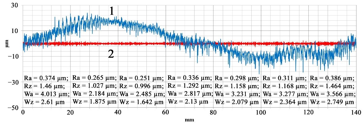
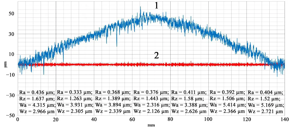
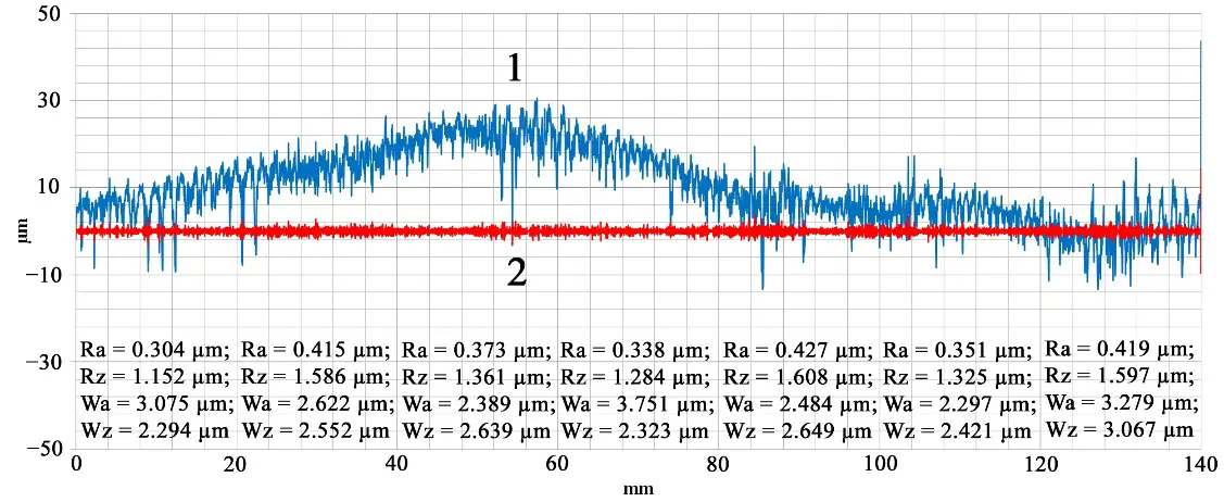
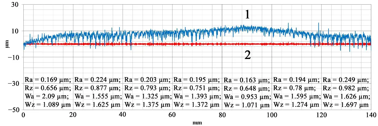
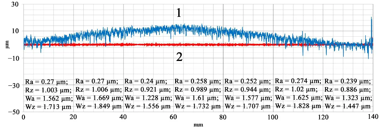
The change in the material removal mechanism when using a diamond-coated milling cutter has a significant impact on the profiles of the machined surfaces, as shown in Figure 7.
 |
|
(a) |
 |
|
(b) |
 |
|
(c) |
 |
|
(d) |
 |
|
(e) |
 |
|
(f) |
Figure 7. Profiles of the end surface (1) of FR4 fiberglass and its quality parameter (2 (RA)) after milling with a diamond-coated tool in the following modes: (a) cutting speed V = 115 m/min, feed fz = 0.15 mm/tooth, (b) cutting speed V = 180 m/min, feed fz = 0.15 mm/tooth, (c) cutting speed V = 230 m/min, feed fz = 0.15 mm/tooth, (d) cutting speed V = 230 m/min, feed fz = 0.075 mm/tooth, (e) cutting speed V = 300 m/min, feed fz = 0.15 mm/tooth, (f) cutting speed V = 300 m/min, feed fz = 0.075 mm/tooth.
The first thing that stands out is the significant improvement in surface quality compared to uncoated and DLC-coated mills. When milling at a cutting speed of V = 115 m/min and a feed rate of fz = 0.15 mm/t, the RA values are 0.2 μm, and the WZ height is 1.3 μm (Figure 7a). As the cutting speed increases, the values of these parameters gradually increase to RA = 0.26 μm and WZ = 1.7 μm at a cutting speed of V = 180 m/min (Figure 7b) and RA = 0.31 μm and WZ = 1.9 μm at V = 230 m/min (Figure 7c). Plate deflection during milling caused by the elasticity of the system also occurs, but its magnitude is significantly lower than for uncoated and DLC cutters, amounting to 10–20 μm. Further increase in the cutting speed to V = 300 m/min still leads to the glass fiber heating above the glass transition point and the loss of its elasticity (Figure 7e). At the same time, the quality parameters deteriorate significantly: RA = 0.36 μm, and WZ = 2.1 μm, probably due to the formation of binder deposits on the cutter cutting edge. When the feed rate is reduced to fz = 0.075 mm/tooth, the surface quality remains almost the same when milling with a diamond-coated tool at a cutting speed of V = 230 m/min: RA = 0.29 μm, WZ = 1.7 μm (Figure 7d). However, at a cutting speed of V = 300 m/min, the surface quality improves significantly: RA = 0.25 μm, WZ = 1.5 μm (Figure 7f), which can be attributed to good diamond thermal conductivity. However, the vibro-diagnostic data suggest that this improvement in roughness is due to the heating of the polymer binder and the beginning of a change in the cutting mechanism of the fiberglass workpiece, similar to the processing of a DLC tool. Therefore, it can be argued that, for a diamond coating, the best quality machined surface on FR4 plastic can be achieved at a relatively low cutting speed and a medium feed rate. In addition, the combination of higher feed per tooth (mm) and lower cutting speed for composition fiber materials reduces the size and shape of harmful dust particles [50].
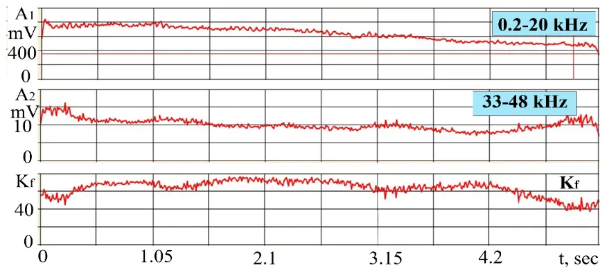
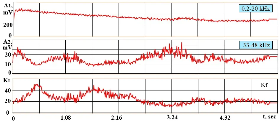
The AE signals RMS recordings in two frequency bands and Kf during processing with a non-coated mill at a cutting speed of V = 180 m/min and a feed rate of fz = 0.15 mm/tooth show (Figure 8a) that the AE amplitude varies unevenly along the entire length of the workpiece, which is determined by changes in the workpiece rigidity. Consequently, the Kf values range from 40 to 75 units. Therefore, the following are the minimum Kf values obtained in the middle of the pass, where the fixture rigidity was stable. For comparison, Figure 8b shows the results for a diamond-coated mill.
 |
|
(a) |
 |
|
(b) |
Figure 8. RMS AE signal recordings in 2 frequency bands and Kf during processing with a non-coated milling cutter (a) and a diamond-coated milling cutter (b) at a cutting speed of V = 180 m/min and a feed rate of fz = 0.15 mm/tooth.
Comparing the curves on Figure 8a with the curves on Figure 8b, the AE amplitudes decreased at low frequencies and increased at high frequencies when working with a diamond-coated mill. At the same time, Kf decreased by several times. If we focus on the middle part of the pass, Kf decreased more than three times. The paradoxical result is that the diamond-coated mill has twice the rounding of the cutting edge compared to the non-coated mill, which should reduce the power density and increase Kf. In this case, the uncoated mill cutting-edge sharpness plays a negative role due to the workpiece low rigidity manifestation in the direction perpendicular to the cutting direction and the workpiece plane. High sharpness of the cutting edge leads to a decrease in normal forces in the contact between the machined surface and the flank surface of the cutter. Therefore, at the moment of the helical tooth cutting, the workpiece can move along the normal to its plane under the action of the axial component of the cutting force, increasing the time of the formation of the chip element and the duration of the corresponding stress pulses, which can be observed in the spectra of AE signals. With a larger rounding radius of the cutting edge, the tension in the contact between the mill and the workpiece increases, providing the workpiece rigidity. The friction force is also influenced by the abrasive properties of the diamond coating surface, which increase the coefficient of friction.
An increase in cutting speed directly affects the power density applied to the workpiece, as the chip element formation and the corresponding stress pulse occur over a shorter period. However, the workpiece low rigidity can have the opposite effect on its displacement during the cutting process. With higher cutting speeds, the workpiece low rigidity has a less significant impact, as surface displacement along the cutter axis is reduced due to the shorter exposure time. Feeding on the mill tooth has less effect on power density, but here too, the influence of workpieces low rigidity can be affected.
Table 6 shows data on AE parameters obtained at cutting speed and feed variations, and at different options of wear-resistant coating on the mill working surface in comparison with the roughness of the processed surface. The given parameters correspond to the moment of processing the middle part of the workpiece.
Table 6. Comparison of AE signal parameters and surface roughness during milling of fiberglass plates.
|
Coating |
V, m/min |
fz, mm/tooth |
Amplitude 0.2–20 kHz, mV |
Amplitude 33–48 kHz, mV |
Parameter Kf |
Roughness RA |
|---|---|---|---|---|---|---|
|
without coating |
115 |
0.15 |
340 |
2.6 |
130 |
0.4 |
|
without coating |
180 |
0.15 |
600 |
4 |
150 |
0.34 |
|
without coating |
230 |
0.075 |
300 |
6 |
50 |
0.26 |
|
DLC |
230 |
0.15 |
510 |
4.9 |
105 |
0.36 |
|
DLC |
300 |
0.15 |
1120 |
4.7 |
240 |
0.36 |
|
DLC |
300 |
0.075 |
470 |
4.7 |
100 |
0.39 |
|
diamond |
115 |
0.15 |
175 |
10 |
17 |
0.2 |
|
diamond |
180 |
0.15 |
300 |
15 |
20 |
0.26 |
|
diamond |
230 |
0.15 |
150 |
6 |
25 |
0.31 |
|
diamond |
230 |
0.075 |
250 |
6.3 |
40 |
0.29 |
|
diamond |
300 |
0.15 |
1350 |
12.3 |
110 |
0.36 |
|
diamond |
300 |
0.075 |
600 |
5.5 |
110 |
0.25 |
From Table 6, it follows that the most significant values of the Kf parameter are observed at large amplitudes of low-frequency vibrations. The best power density indicators (Kf from 17 to 25) were obtained when diamond-coated cutters. However, at a cutting speed of V = 300 m/min, the efficiency of these cutters was significantly reduced, the Kf parameter increased to 110, and was comparable to Kf for DLC mills processing. There is also an apparent correlation between the Kf parameter values and the roughness values of the end surface of the fiberglass plate, which allows us to control the surface quality parameters by establishing a feedback loop based on the Kf value and changing the cutting modes during the processing process, provided that the technical specifications of the machine equipment allow for this.
4. Conclusions
Cutting of polymer composites is associated with a number of problems caused by the properties of the constituent materials. The presented work includes an experimental analysis of the processes occurring during the milling of fiberglass reinforced plastic sheet by a tool with wear-resistant coatings based on carbon with diamond and diamond-like structure, which allows for drawing some conclusions based on the study results.
-
The coating material of the tungsten carbide end mills and the cutting mode have a predominant effect on the roughness of the FR4 fiberglass workpiece’s surface. The diamond-coated tool showed the best results. The minimum roughness value obtained in the experiment was RA = 0.2 μm, and the irregularities height was WZ = 1.3 μm.
-
The use of cutting modes that minimize excessive heat generation can improve the quality of the machined surface. To achieve this, it is important to choose relatively low cutting speeds and appropriate feed rates to avoid melting of the polymer matrix and resin buildup on the cutting edge. However, it is possible to significantly improve processing performance by increasing the cutting speed if relaxing the surface roughness requirements to RA = 0.36 μm. Experiments have shown that in this case, the use of wear-resistant coatings allows for an increase in the processing performance of fiberglass by end mills by 1.3 times (from 180 to 230 m/min) for a tool with DLC, and by 1.7 times (from 180 to 300 m/min) for a diamond-coated mill. Reducing the feed to the tooth did not improve the quality parameters of the treated surface of the FR4 fiberglass with a tool of a given geometry, as it increases the time of tool-work interaction and the probability of exceeding the glass transition temperature of the composite in the cutting zone.
-
Studies of vibration signals have shown that the frequency ranges up to 20 kHz and from 33 to 48 kHz are sufficiently informative for monitoring the milling process of FR4 sheet fiberglass plastic. The highest values of the Kf parameter, which is the ratio of the RMS amplitudes of signals in the low-frequency and high-frequency ranges, were observed at high amplitudes of low-frequency vibrations that reduce the quality of processing, which is typical for processing with a mill without coating and with DLC. The lowest Kf values were obtained when diamond-coated mills were used at different speeds, but only at a higher feed rate. However, at a cutting speed of V = 300 m/min, the Kf parameter increased, indicating a decrease in this tool efficiency.
-
A correlation was revealed between the values of the Kf parameter and the roughness values of the treated fiberglass plate surface.
In most of the published materials on the fiberglass sheets processing, the authors use relatively small diameter milling cutters on high-speed machines. Unfortunately, in this case, the features of the interaction of the tool and the workpiece are quite difficult to identify due to the insufficient rigidity of the system. The authors express the hope that this study can help interested technologists in choosing a tool with a wear-resistant coating and assigning appropriate cutting modes to increase the efficiency of processing this difficult-to-process material. In the future, it is planned to use the considered approach to optimize the parameters of the diamond coating on small-diameter milling cutters designed for processing printed circuit boards.
Author Contributions
Conceptualization, S.V.F., S.N.G. and V.I.K.; methodology, E.E.A. and M.P.K.; software, M.P.K. and A.A.E.; validation, A.A.E. and S.V.F.; formal analysis, A.A.E., E.S.M. and A.P.L.; investigation, S.V.F. and M.P.K.; resources, S.N.G. and V.I.K.; data curation, E.S.M. and A.P.L.; writing—original draft preparation, S.V.F., M.P.K. and E.E.A.; writing—review and editing, S.V.F.; supervision, S.N.G. and V.I.K.; project administration S.N.G. and S.V.F.; funding acquisition, S.N.G. All authors have read and agreed to the published version of the manuscript.
Ethics Statement
Not applicable.
Informed Consent Statement
Not applicable.
Data Availability Statement
The original contributions presented in this study are included in the article; further inquiries can be directed to the corresponding author.
Funding
This research was carried out at the expense of the grant of the Russian Science Foundation No. 22-19-00694.
Declaration of Competing Interest
The authors declare that they have no known competing financial interests or personal relationships that could have appeared to influence the work reported in this paper.
References
- Cevahir A. Glass fibers. In Fiber Technology for Fiber-Reinforced Composites, 1st ed.; Woodhead Publishing: Cambridge, UK, 2017; pp. 99–121. DOI:10.1016/B978-0-08-101871-2.00005-9 [Google Scholar]
- Schlegel M, Folea M, Roman A, Nardin P. Analysis of Machined Fiber Glass Composite Material. Recent Researches in Manufacturing Engineering. 2011, pp. 152–155. Available online: https://www.academia.edu/89092964/Surface_Analysis_of_Machined_Fiber_Glass_Composite_Material (accessed on 15 December 2025).
- Quadrini F, Squio EA, Tagliaferri V. Machining of glass fiber reinforced polyamide. Express Polym. Lett. 2007, 1, 810–816. DOI:10.3144/expresspolymlett.2007.112 [Google Scholar]
- Elgnemi T, Songmene V, Kouam J, Jun MBG, Samuel AM. Experimental Investigation on Dry Routing of CFRP Composite: Temperature, Forces, Tool Wear, and Fine Dust Emission. Materials 2021, 14, 5697. DOI:10.3390/ma14195697 [Google Scholar]
- Khan MA, Rahat MR, Ahmed U, Jamila M, Ali AM, Zhao G, et al. The Recent Advancements in Minimum Quantity Lubrication (MQL) and Its Application in Mechanical Machining—A State-of-the-Art Review. Lubricants 2025, 13, 401. DOI:10.3390/lubricants13090401 [Google Scholar]
- Azmi AI, Lin RJT, Bhattacharyya D. Machinability study of glass fibre-reinforced polymer composites during end milling. Int. J. Adv. Manuf. Technol. 2012, 64, 247–261. DOI:10.1007/s00170-012-4006-6 [Google Scholar]
- Tima T, Geier N. Machining-Induced Burr Suppression in Edge Trimming of Carbon Fibre-Reinforced Polymer (CFRP) Composites by Tool Tilting. J. Manuf. Mater. Process. 2024, 8, 247. DOI:10.3390/jmmp8060247 [Google Scholar]
- Bilek O, Reznicek M, Matras A, Solarik T, Macku L. An Experimental Investigation into Trochoidal Milling for High-Quality GFRP Machining. Materials 2025, 18, 1669. DOI:10.3390/ma18071669 [Google Scholar]
- Li Z, Niu J, Sun S, Sun Y. A parameter-variant trochoidal-like tool path planning method for chatter-free and high-efficiency milling. Chin. J. Aeronaut. 2025, 38, 103082. DOI:10.1016/j.cja.2024.05.038 [Google Scholar]
- Yang M, Sun C. Sustainable Machining for Difficult-to-Cutting Materials. Intell. Sustain. Manuf. 2025, 2, 10012. DOI:10.70322/ism.2025.10012 [Google Scholar]
- Slamani M, Chatelet J-F. A review on the machining of polymer composites reinforced with carbon (CFRP), glass (GFRP), and natural fibers (NFRP). J. Discov. Mech. Eng. 2023, 2, 4. DOI:10.1007/s44245-023-00011-w [Google Scholar]
- Gafarova VA, Kuzeev IR. Destruction of Epoxy-Based Composite Materials under the Influence of Impact Load. Mater. Sci. Forum 2020, 992, 331–335. DOI:10.4028/www.scientific.net/MSF.992.331 [Google Scholar]
- Çelik YH, Kılıçkap E, Yardımeden A. Estimate of cutting forces and surface roughness in end milling of glass fiber reinforced plastic composites using fuzzy logic system. Sci. Eng. Compos. Mater. 2014, 21, 435–443. DOI:10.1515/secm-2013-0129 [Google Scholar]
- Sun M, Guo K, Sivalingam V, Sun J, Li D, Huang T. Understanding the tool wear mechanism during robotic milling of glass fibre reinforced plastic. Tribol. Int. 2024, 195, 109648. DOI:10.1016/j.triboint.2024.109648 [Google Scholar]
- Priya IIM, Palanikumar K, Senthilkumar N, Prabha PS. Investigation of delamination and surface roughness in end milling of glass fibre reinforced polymer composites using Fuzzy Model and Grey wolf Optimizer. Int. J. Interact. Des. Manuf. 2023, 18, 749–769. DOI:10.1007/s12008-023-01576-2 [Google Scholar]
- Hu H, Du B, Ning S, Zhang H, Wang Z, Xiong Y, et al. Milling Parameter Optimization of Continuous-Glass-Fiber-Reinforced-Polypropylene Laminate. Materials 2022, 15, 2703. DOI:10.3390/ma15072703 [Google Scholar]
- Rychkov D, Lobanov D, Kuznetsov A, Bratan S, Gorbatyuk S, Leonov S, et al. Achieving high quality surface of laminated glass-reinforced plastics during milling. MATEC Web Conf. 2018, 224, 01044. DOI:10.1051/matecconf/201822401044 [Google Scholar]
- Dabhade SS. Study of Surface Roughness Characteristics of Drilled Hole in Glass Fiber Reinforced Plastic (GFRP) by CNC Milling. Int. J. Eng. Res. Appl. 2016, 6, 34–38. [Google Scholar]
- Ducobu F, Mélice E, Rivière-Lorphèvre E, Beuscart T, Aizpuru O, Granjon A, et al. Sensitivity Analysis of Various Geometries of PCD and Cemented Tungsten Carbide Cutting Tools during the Milling of GFRP Composite. Polymers 2022, 14, 1524. DOI:10.3390/polym14081524 [Google Scholar]
- Zawada-Michałowska M, Pieśko P, Legutko S. Effect of the Cutting Tool on the Quality of a Machined Composite Part. Manuf. Technol. 2023, 23, 870–879. DOI:10.21062/mft.2023.107 [Google Scholar]
- Knap A, Dvořáčková Š, Knápek T. Study of the Machining Process of GFRP Materials by Milling Technology with Coated Tools. Coatings 2022, 12, 1354. DOI:10.3390/coatings12091354 [Google Scholar]
- Grigoriev SN, Volosova MA, Vereschaka AA, Sitnikov NN, Milovich F, Bublikov JI, et al. Properties of (Cr,Al,Si)N-(DLC-Si) composite coatings deposited on a cutting ceramic substrate. Ceram. Int. 2020, 46, 18241–18255. DOI:10.1016/j.ceramint.2020.04.147 [Google Scholar]
- Schrab B, Collaine A, Freyburger J-M, Tourlonias M. Machinability analysis of UD-GFRP composites in edge trimming with diamond-coated burr tools at various fiber orientations. CIRP J. Manuf. Sci. Technol. 2025, 59, 194–206. DOI:10.1016/j.cirpj.2025.03.008 [Google Scholar]
- Ashkinazi E, Fedorov S, Khomich A, Rogalin V, Bolshakov A, Sovyk D, et al. Technology Features of Diamond Coating Deposition on a Carbide Tool. C 2022, 8, 77. DOI:10.3390/c8040077 [Google Scholar]
- Duan Z, Xi S, Wang S, Wang Z, Bian P, Li C, et al. Identification of Cutting Workpiece Surface Defects Based on an Improved Single Shot Multibox Detector. Intell. Sustain. Manuf. 2024, 1, 10020. DOI:10.70322/ism.2024.10020 [Google Scholar]
- Kecik K, Ciecielag K, Zaleski K. Damage detection by recurrence and entropy methods on the basis of time series measured during composite milling. Int. J. Adv. Manuf. Technol. 2020, 111, 549–563. DOI:10.1007/s00170-020-06036-9 [Google Scholar]
- Panasiuk K, Dudzik K. Determining the Stages of Deformation and Destruction of Composite Materials in a Static Tensile Test by Acoustic Emission. Materials 2022, 15, 313. DOI:10.3390/ma15010313 [Google Scholar]
- Kozochkin MP, Volosova MA, Allenov DG. Effect of wear of tool cutting edge on detail surface layer deformation and parameters of vibro-acoustic signals. Mater. Sci. Forum 2016, 876, 50–58. DOI:10.4028/www.scientific.net/MSF.876.50 [Google Scholar]
- Aggelis DG, Kordatos EZ, Matikas TE. Monitoring of metal fatigue damage using acoustic emission and thermography. J. Acoust. Emiss. 2011, 29, 113–122. [Google Scholar]
- Gershman I, Mironov A, Fox-Rabinovich G, Muravyeva T, Shkalei I, Shcherbakova O, Torskaya E, Fedorov S, Endrino JL. Secondary Structures on the Friction Surface of Diamond-like Coating. Coatings 2022, 12, 1685. DOI:10.3390/coatings12111685 [Google Scholar]
- Ashkinazi EE, Fedorov SV, Martyanov AK, Sedov VS, Popovich AF, Bolshakov AP, et al. Evolution of the Growth of a Micro-Nano Crystalline Diamond Film on an Axial Carbide Tool Model in Microwave Plasma. Coatings 2023, 13, 1156. DOI:10.3390/coatings13071156 [Google Scholar]
- Lu F, Hao T, Bai X, Fu Z. Research on the innovative pretreatment to improve the adhesion and performance of diamond coatings. Fuller. Nanotub. Carbon Nanostruct. 2022, 30, 1002–1010. DOI:10.1080/1536383X.2022.2054993 [Google Scholar]
- Sedov V, Martyanov A, Ashkinazi E, Tiazhelov I, Savin S, Sovyk D, et al. Effect of diamond seeds size on the adhesion of CVD diamond coatings on WC-Co instrument. Surf. Interfaces 2023, 38, 102861. DOI:10.1016/j.surfin.2023.102861 [Google Scholar]
- Wang H, Yang J, Sun F. Cutting performances of MCD, SMCD, NCD and MCD/NCD coated tools in high-speed milling of hot bending graphite molds. J. Mater. Process. Technol. 2020, 276, 116401. DOI:10.1016/j.jmatprotec.2019.116401 [Google Scholar]
- Ashkinazi EE, Fedorov SV, Martyanov AK, Sovyk DN, Ralchenko VG, Litvinov AP, et al. Wear of End Mills with Carbon Coatings When Aluminum Alloy A97075 High-Speed Processing. Metals 2024, 14, 1344. DOI:10.3390/met14121344 [Google Scholar]
- Grigoriev SN, Kozochkin MP, Porvatov AN, Fedorov SV, Malakhinsky AP, Melnik YA. Investigation of the Information Possibilities of the Parameters of Vibroacoustic Signals Accompanying the Processing of Materials by Concentrated Energy Flows. Sensors 2023, 23, 750. DOI:10.3390/s23020750 [Google Scholar]
- Razali N, Sultan MTH, Mustapha F, Yidris N, Ishak MR. Impact Damage on Composite Structures—A Review. Int. J. Eng. Sci. 2014, 3, 8–20. [Google Scholar]
- Rabiee A, Ghasemnejad H. Progressive Crushing of Polymer Matrix Composite Tubular Structures: Review. Open J. Compos. Mater. 2017, 7, 14–48. DOI:10.4236/ojcm.2017.71002 [Google Scholar]
- Wu J, Wang H, Gao Y, Sun L. Research on damage evolution mechanisms under compressive and tensile tests of plain weave SiCf/SiC composites using in situ X-ray CT. J. Sci. Eng. Compos. Mater. 2024, 31, 20220233. DOI:10.1515/secm-2022-0233 [Google Scholar]
- Nguen-Dinh N, Bouvet C, Zitoune R. Influence of machining damage generated during trimming of CFRP composite on the compressive strength. J. Compos. Mater. 2019, 54, 1413–1430. DOI:10.1177/0021998319883335 [Google Scholar]
- Rai A, Mouria P, Gulati V, Katyal P. Evaluation of Milling Parameters on Fiberglass to Reduce the Surface Roughness. Int. J. Innov. Res. Sci. Eng. Technol. 2013, 4, 1224–1230. [Google Scholar]
- Shahabaz SM, Sharma S, Shetty N, Shetty SD, Gowrishankar MC. Influence of Temperature on Mechanical Properties and Machining of Fibre Reinforced Polymer Composites: A Review. Eng. Sci. 2021, 16, 26–46. DOI:10.30919/es8d553 [Google Scholar]
- Spanu P, Abaza BF, Constantinescu TC. Analysis and Prediction of Temperature Using an Artificial Neural Network Model for Milling Glass Fiber Reinforced Polymer Composites. Polymers 2024, 16, 3283. DOI:10.3390/polym16233283 [Google Scholar]
- Anjaneyulu B, Rao GN, Prahladarao DK, Harshavardhan D. Analysis of Process Parameters in Milling of Glass Fibre Reinforced Plastic Composites. Int. J. Mech. Eng. Technol. 2017, 8, 149–159. [Google Scholar]
- An Q, Zhang J, Xiao G, Xu C, Yi M, Chen Z, et al. Fiber Orientation Effects in CFRPMilling: Multiscale Characterization of Cutting Dynamics, Surface Integrity, and Damage Mechanisms. J. Compos. Sci. 2025, 9, 342. DOI:10.3390/jcs9070342 [Google Scholar]
- Gao T, Zhang Y, Li C, Wang Y, Chen Y, An Q, et al. Fiber-reinforced composites in milling and grinding: Machining bottlenecks and advanced strategies. Front. Mech. Eng. 2022, 17, 24. DOI:10.1007/s11465-022-0680-8 [Google Scholar]
- Hashimoto M, Kanda K. Mechanism of Low Friction Coefficient of the Diamond-Like Carbon Film. J. Surf. Finish. Soc. Jpn. 2017, 68, 48–53. DOI:10.4139/sfj.68.48 [Google Scholar]
- Mallik AK, Dandapat N, Chakraborty S, Mandal AK, Ghosh J, Unnikrishnan M, et al. Characterizations of microwave plasma CVD grown polycrystalline diamond coatings for advanced technological applications. Process. Appl. Ceram. 2014, 8, 69–80. DOI:10.2298/PAC1402069M [Google Scholar]
- Pathak SR, Sharma P, Mali H, Malik A. Optimization of machining parameters during milling on glass fiber-reinforced textile composite. Multiscale Multidiscip. Model. Exp. Des. 2024, 7, 249–261. DOI:10.1007/s41939-023-00204-6 [Google Scholar]
- Dvorácková Š, Kroisová D, Knápek T, Vána M. Effect of Cutting Conditions on the Size of Dust Particles Generated during Milling of Carbon Fibre-Reinforced Composite Materials. Polymers 2024, 16, 2559. DOI:10.3390/polym16182559 [Google Scholar]