Using a MOF of Wetted Quasi [Zn4O(bdc)3] as Both the Battery Separator and the Electrolyte to Prepare All-Solid-State Batteries of Both ASS-LTO/Li and ASS-Gr/Li

Using a MOF of Wetted Quasi [Zn4O(bdc)3] as Both the Battery Separator and the Electrolyte to Prepare All-Solid-State Batteries of Both ASS-LTO/Li and ASS-Gr/Li
Keqiang Ding 1,2,* Yiqing Chen 1 Jiawen Bao 1 Qian Zhao 1 Mengqing Niu 1 Wanting Shi 1 Hui Wang 2
Received: 09 December 2025 Revised: 30 December 2025 Accepted: 05 January 2026 Published: 07 January 2026

© 2026 The authors. This is an open access article under the Creative Commons Attribution 4.0 International License (https://creativecommons.org/licenses/by/4.0/).
1. Introduction
Lithium-ion batteries (LIBs), due to their high energy density, long cycle life and absence of memory effect, have been regarded as third-generation energy storage systems, which play a significant role in the development of today’s human society [1]. In general, a conventional LIB is constituted by an anode, an electrolyte solution, a separator, and a cathode [2]. Thermal runaway, which usually occurs when the LIBs are subjected to the internal short circuits, overcharging, or mechanical damage, is regarded as the main reason to generate safety issues of LIBs [3]. With further research, the decomposition of the electrolyte solution of a LIB is also investigated as one of the direct reasons causing safety accidents of LIBs [4]. Therefore, developing all-solid-state lithium batteries is thought to be one of the most feasible ways to prevent accidents of LIBs, such as explosions from occurring [5].
An all-solid-state lithium battery (denoted as ASS-Li battery) is generally constituted by a cathode, an anode, and a solid-state electrolyte [6]. Due to the absence of a battery separator and the electrolyte solution, besides the relatively higher energy density, the high security of the ASS-Li battery is considered to be an irreplaceable advantage of other batteries [7]. Thus, exploring novel ASS-Li batteries has become a research hotspot in the lithium battery research field [8]. On the basis of the literature survey results, generally, the cathode materials of ASS-Li batteries mainly include LiNi0.5Mn1.5O4 [9], LiCoO2 [10], xLi2MnO3·(1−x)LiMO2 (M = Co, Mn, Ni) [11], LiCoPO4 [12] and LiNiPO4 [13], and, the main anode materials of ASS-Li batteries usually refer to the graphite [14], Li4Ti5O12 [15], silicon [16] and lithium metal [17]. Ordinarily, the solid-state electrolytes (SSEs) used in an ASS-Li battery are primarily categorized into three major types, i.e., inorganic solid-state electrolytes (ISSEs), polymer solid-state electrolytes (PSSEs), and composite solid-state electrolytes (CSSEs) [18]. Furthermore, the inorganic solid-state electrolytes were usually divided into three categories [19], namely, oxide-based, sulfide-based, and halide-based inorganic ISSEs. Polymer solid-state electrolytes were also classified into three classes: solid polymer electrolytes, gel polymer electrolytes, and composite polymer electrolytes [20].
Compared to other kinds of SSEs, the high mechanical strength, high physical and chemical stability, and high safety enable the inorganic solid electrolytes to stand out from the ordinary SSEs [19]. For example, Seetawan’s group [21] prepared a LFP (LiFePO4)/Li battery using cubic-Li0.5La0.5TiO3 as the solid-state electrolyte, revealing that the initial discharge capacity of LFP/10 wt% LLSr0.09TTa0.09O3/Li full battery at 0.1 C was 156 mAh·g−1, and the discharge capacity of the as-prepared battery at 1 C was maintained to be about 93 mAh·g−1 after 100 cycles. A sulfide-based all-solid-state lithium-ion battery (ASSLIBs) of NCM88-S/Li6PS5Cl/Li4Ti5O12 was prepared by Wu’s group [22], which delivered, respectively, a discharge capacity of 200.7 mAh·g−1 at 0.01 C and 150.0 mAh·g−1 at 1 C. Sun’s research [23] team synthesized a series of iodide solid electrolytes (SEs, LixYI3+x (x = 2, 3, 4, or 9) ), reporting that the prepared SEs of Li4YI7 could be used as the solid-state electrolyte to prepare an ASSLIBs Li-S battery. In Sun’s work [23], the resultant battery with an S (sulfur) loading of 2.04 mg·cm−2 delivered a discharge capacity over 900 mAh·g−1 at 0.225 mA·cm−2.
Polymer solid-state electrolytes, due to their unique advantages such as excellent flexibilities, a certain degree of scalability as well as and the good processabilities, are also a kind of promising solid-state electrolyte, which is generally considered to be one of the closest solid-state electrolytes to realizing the commercial solid-state lithium batteries [24]. For example, Yuan’s group [25] prepared a composite skeleton that was integrated by boron nitride nanofibers (BNNFs) and lithiated nafion (Linafion) mosaics, via which a honeycomb-like skeleton PH-BN/LN containing poly(vinylidene fluoride-co-hexafluoropropylene) (PVDF-HFP), boron nitride nanofibers (BNNFs) and lithiated Nafion (Linafion) was fabricated, further revealing that the discharge capacity of the solid-sate battery that was constructed by Li, solid-state electrolyte (SSEs) of PH-BN/LN and NCM811 was about 65 mAh·g−1 at 1 C. Yao et al. [26] prepared a novel dual-polymer@inorganic network CSE (DNSE@IN) through a sequential nonhydrolytic sol-gel reaction, via which the DNSE@IN based Li/LiFePO4 cell was produced. In Yao’s work [26], the initial discharge capacity of the Li/DNSE@IN/LFP cell was as high as 164.6 mAh·g−1 at 0.1 C. Xue’s group [27] develop a novel poly(benzoxazine-propylene-oxide)-based gel polymer electrolyte (GPE) (PBz-PO-GPE), revealing that the PBz-PO-GPE 2000 assembled LiFePO4||Li full cells delivered an initial discharge 140.7 mAh·g−1 at 2 C rate.
Being different from inorganic solid-state electrolytes and polymer solid-state electrolytes, the properties of excellent interfacial compatibility and good flexibility are regarded as the main merits of using the composite solid-state electrolytes (also called organic and inorganic composite solid electrolyte) to establish the all-solid-state lithium batteries [28]. For instance, Gao’s group [29] blended a highly ionically conductive Li6.5La3Zr1.5Ta0.1Nb0.4O12 (LLZTNO) filler into a poly(ethylene oxide) matrix, generating a novel composite solid-state electrolyte (CSSE), finding that the conductivity of the prepared CSSE, namely, PEO (polyethylene oxide)-LiTFSI (lithium bis(trifluoromethanesulfonyl)imide)-10% LLZTNO (i.e., PL-LLZTNO10%), was as high as 0.36 × 10⁻⁴ S·cm−1 at room temperature. In Gao’s work [29], the discharge capacity of LFP/PL-LLZTNO10%/Li cell was measured to be about 158.3 mAh·g−1 at 0.2 C, a relatively higher capacity value. Although, as introduced above, the research works on solid-state electrolytes have made significant progress in recent years, the relatively higher interface resistance, poor thermal stability and the lower ion conductivity are, respectively, studied as the main drawbacks of ISSEs, PSSEs, and CSSEs [28,30,31]. In other words, exploring new SSEs is still a challenge in the research field of all- solid-state lithium batteries [32].
As a novel kind of material, the material with a metal-organic framework (namely, MOF), because of its unique advantages, such as the higher specific surface area, the tunable pore structures, as well as the rich chemical reactivity [33], has been paid much attention ever since its inception [34]. The metal-organic frameworks-5 (MOF-5) is a kind of zinc-based MOF, in which the benzene dicarboxylic acid is employed as the crystal bifunctional bridging ligand and the [Zn4O]6+ inorganic moiety as the vertex [35]. The MOF-5, primarily due to its large pores and high surface area, has been considered one of the most well-known compounds of MOFs, and is extensively applied in various research fields. For example, Zhang’s group [36] constructed a customized hydrophobic porous shell of NTU-COF on the particularly fragile MOF-5 via a “plug-socket anchoring” strategy, revealing that the complete CO2/N2 separation under humid conditions was well achieved by the newly developed structure of NTU-COF/MOF-5. Farzad et al. [37] investigated the interactions between the derived MOF-5 and phenolic compounds via molecular dynamics (MD) and well-tempered metadynamics (WTMD) simulation methods, indicating that F-MOF-5 was a more suitable adsorbent than MOF-5 and CH3-MOF-5 for phenolic pollutants removal from the environment. Balarak’s group [38] combined magnetic nanoparticles of Fe3O4 with an organic-inorganic framework of MOF-5, forming a novel substance of MOF-5@Fe3O4, which, as a photocatalytic activating agent, exhibited an outstanding degradation performance towards AB113. Shokry et al. [35] prepared metal-organic framework-5 (MOF-5) and cobalt-doped MOF-5 via a solvothermal method for detecting greenhouse gases, reporting that MOF-5 doped with a 10 wt% ratio of cobalt showed the highest sensor device response toward N2O. Although MOF-5 has been used in some research areas, MOF-5, especially the MOF-5 of [Zn4O(bdc)3], has not yet been employed as a solid-state electrolyte to assemble ASS-LTO/Li and ASS-Gr/Li, to our knowledge.
In the present work, firstly, a kind of MOF (also called MOF-5), namely, [Zn4O(bdc)3], was carefully prepared according to the previous work [39]. Although the presence of a benzene ring and C=C in [Zn4O(bdc)3] was effectively indicated by the FTIR results, EDS results indicated that the as-prepared sample was a quasi [Zn4O(bdc)3] rather than a pure [Zn4O(bdc)3]. After that, the wetted quasi [Zn4O(bdc)3] was employed as both the separator and the solid-state electrolyte to assemble an all-solid-state lithium battery of LTO/Li (ASS-LTO/Li). The as-prepared ASS-LTO/Li delivered an initial discharge capacity of 286.4 mAh·g−1 at 0.2 C. Interestingly, when the resultant ASS-LTO/Li battery was cycled for 100 cycles at 1 C, its discharge capacity was still maintained to be about 125 mAh·g−1. The obtained wetted quasi [Zn4O(bdc)3] was also used to prepare an all-solid-state lithium battery of Gr/Li (ASS-Gr/Li). The initial discharge capacity of ASS-Gr/Li at 0.2 C was measured to be about 169 mAh·g−1, an acceptable value. However, as the applied current density was increased to 1.0 A·g−1, ASS-Gr/Li exhibited a discharge capacity of 24 mAh·g−1, which decreased to approximately 12 mAh·g−1 after 100 cycles, indicating poor long-term high-rate performance. It is admitted that the electrochemical performances of both ASS-LTO/Li and Gr/Li were poor as compared to the state-of-the-art all-solid-state lithium battery. Nevertheless, this pioneering work was not only very helpful for expanding the application areas of MOF but also very beneficial for the development of all-solid-state lithium batteries.
2. Experimental
2.1. Materials
Acetylene black (denoted as AB) was bought from Anhui Zesheng Technology Co., Ltd. (Hefei, China). The copper foil, the binder of PVDF (polyvinylidene fluoride) and graphite were all donated from Hebei Lingdian New Energy Technology Co., Ltd. (Tangshan, China). N-methylpyrrolidone (NMP), zinc acetate ((CH3COO)2Zn), triethylamine ((CH3CH2)3N), terephthalic acid (TPA), dimethylformamide (DMF) and methanol (CH3OH) were all purchased from Tianjin Zhiyuan Chemical Reagent Co., Ltd. (Tianjin, China). The electrode material of lithium titanate (Li4Ti5O12, LTO) was provided by Shanghai Aladdin Biochemical Technology Co., Ltd. (Shanghai, China). The 1M LiFP6 electrolyte solution used in assembling the batteries was supplied by Nanjing Mojiesi Energy Technology Co., Ltd. (Nanjing, China). The lithium foil and battery testing molds were bought from Tianjin Liangnuo Technology Development Co., Ltd. (Tianjin, China).
2.2. Preparation of the Quasi [Zn4O(bdc)3]
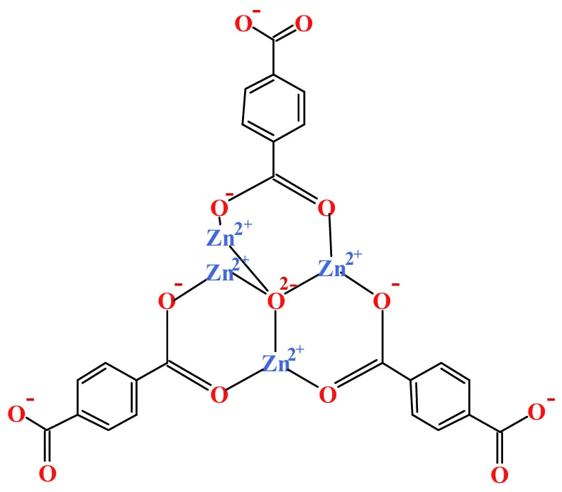
Firstly, 2.125 g of TPA was dissolved in 50 mL of DMF, generating a solution. Immediately, 1 mL of triethylamine ((CH3CH2)3N) and 3 mL of deionized water were successively added to the above resulting solution so as to prepare solution A. At the same time, 0.625 g of zinc acetate ((CH3COO)2Zn) was dissolved in 62.5 mL of DMF, leading to the formation of solution B. Subsequently, solution A was slowly added dropwise into solution B while stirring. More specifically, it will take 30 min to complete the above mixing process. At the end of the above mixing process, the resulting solution was still stirred at 1000 rpm for another 4 h so as to acquire a white suspension solution. After being well filtered, the obtained white precipitates were rinsed successively using 100 mL of DMF and 50 mL of methanol, aiming to prepare a well cleaned product. At last, the resulting white solid was dried in air at 80 °C for 6 h to produce the final product of [Zn4O(bdc)3] [39]. As shown by the structural diagram of [Zn4O(bdc)3] (Zn4O13C24H12) shown in Figure 1, Zn2+, O−, benzene ring, and C=C were present in [Zn4O(bdc)3], which endowed the as-prepared [Zn4O(bdc)3] a certain level of conductivity, also being the reason urging us to use [Zn4O(bdc)3] as both the separator and the solid electrolyte for the all-solid-state lithium batteries.
2.3. Preparation of ASS-LTO/Li and ASS-Gr/Li Batteries
Prior to the assembly of the batteries, the LTO [40] and graphite electrodes [41] were successively prepared carefully. A mixture containing LTO, PVDF, and AB was carefully placed in an agate mortar, in which the mass ratio of LTO (0.3 g), PVDF (0.0375 g), and AB (0.0375 g) was 8:1:1. Then, the resulting mixture was thoroughly ground for 10 min, aiming to form a uniform mixture. Subsequently, several drops of NMP were added dropwise into above resultant mixture while stirring so as to prepare a mud like paste. Next, the resulting paste was carefully applied to a copper foil surface using a piece of glass. Soon afterwards, the resulting paste coated copper foil was dried in a vacuum oven at 120 °C for 6 h to remove the volatile solvents as much as possible. After being cooled naturally to room temperature, an LTO electrode (the diameter of the LTO electrode was about 9.67 mm) was prepared successfully. The preparation process of the graphite electrode, except for using graphite to replace LTO, was the same as that of preparing the LTO electrode.
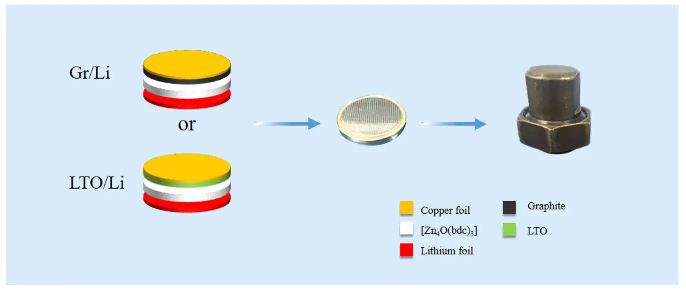
The preparation process of ASS-LTO/Li was as follows. Firstly, an LTO electrode was carefully placed on the inner surface of a battery shell of a coin cell, and then, 3 drops of 1M LiFP6 were dropped onto the surface of the LTO electrode, generating a wetted LTO electrode. Here, the electrolyte solution of 1M LiPF6 was prepared through dissolving a proper amount of LiPF6 in a mixed organic solvent consisting of ethyl methyl carbonate (EMC), ethylene carbonate (EC), dimethyl carbonate (DMC) and vinylene carbonate (VC) (the volume ratio of EMC, EC, DMC and VC was 1:1:1:1). Subsequently, 0.02 g of [Zn4O(bdc)3] powder was carefully spread evenly on the surface of the wetted LTO electrode forming a [Zn4O(bdc)3] powder layer with a thickness of about 1mm. Soon afterwards, 0.1 mL of 1M LiPF6 was again dropped on the surface of the resultant [Zn4O(bdc)3] powder layer to prepare a well wetted [Zn4O(bdc)3] powder layer. And then, a lithium foil was placed carefully on the wetted [Zn4O(bdc)3] powder layer. Thereafter, an iron sheet-shaped back-up plate and the other battery shell of the coin cell were successively coated on the surface of the lithium foil. Finally, the resulting coin cell was well sealed in a home-made battery mold to end the preparation process of the ASS-LTO/Li. Summarily, as shown in Figure 2, the newly assembled lithium battery of ASS-LTO/Li had a sandwiched structure, in which a lithium foil, a wetted [Zn4O(bdc)3] powder layer and a conventional LTO were tightly compressed together. The assembly process of the ASS-Gr/Li battery, besides using graphite to substitute for LTO, was identical to that of preparing the ASS-LTO/Li battery. It should be noted that all the assembly processes of both ASS-LTO/Li and ASS-Gr/Li batteries were accomplished in a nitrogen-filled glove box. Apparently, for ASS-LTO/Li and ASS-Gr/Li batteries, LTO and graphite were employed as the positive electrode, and lithium foil was utilized as the negative electrode. Here, the current rate applied to the ASS-LTO/Li battery was calculated based on the theoretical capacity of LTO (1 C = 175 mA·g−1).
2.4. Characterizations
The functional groups existing in the studied samples were characterized by FTIR (Fourier Transform Infrared Spectroscopy, Nicolet iS50, USA). The chemical components of the studied samples were preliminarily examined through analyzing XRD patterns that were measured on a X-ray diffractometer (XRD, X-ray diffractometer, Rigaku SmartLab, Japan). EDS (energy-dispersive X-ray spectra, Phenom Pharos G2, The Netherlands) was utilized to roughly determine the element contents of the studied samples. The surface morphology of the studied samples was observed by the SEM images that were measured on a scanning electron microscopy (SEM, scanning electron microscopy, S-4800, Japan).
The battery performances of both ASS-LTO/Li and ASS-Gr/Li were evaluated on a galvanostatic charge-discharge tester of CT-3008W-5V20mA-S4 (Shenzhen Neware Electronics Co., Ltd., Shenzhen, China). Other electrochemical measurements, such as cyclic voltammetry (CV) and electrochemical impedance spectroscopy (EIS), were all carried out on a CHI660E electrochemical workstation (Shanghai Chenhua Apparatus, Shanghai, China). The potential ranges of CV measurement for the ASS-LTO/Li and ASS-Gr/Li were, respectively, 1.0–2.5 V and 0.01–3.00 V. And the frequency range and amplitude of alternating current (AC) used for recording the Nyquist plots were, respectively, from 0.1 Hz to 105 Hz and 10 mV. It should be emphasized that all experiments were performed at room temperature, and no special protective devices were used while conducting the experiments.
3. Results and Discussion
3.1. Characterization of [Zn4O(bdc)3]
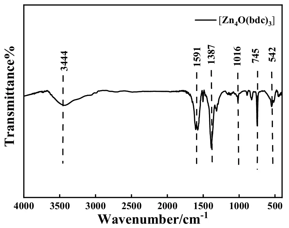
The FTIR spectra of the as-synthesized [Zn4O(bdc)3] are shown in Figure 3. The broad and distinct absorption band positioned at 3444 cm−1 was usually attributed to the stretching vibration of –OH groups [42]. According to the previous work [43], the absorption band located at 1591 cm−1 originated from the asymmetric stretching of the carboxylic group, and the peak positioned at 1387 cm−1 was caused by the symmetric stretching of the carboxylic group in 1,4-benzene dicarboxylic acid. The small absorption band at 1016 cm−1 resulted from the stretching of the C=O group [44]. In general, the sharp and narrow absorption band at 745 cm−1 originated from the out-of-plane bending of the aromatic –C–H group [45]. Additionally, the absorption band at 542 cm−1 was reported to be from the Zn-O stretching vibration of the tetrahedral Zn4O metal cluster [35]. Thus, the presence of the carboxylic group, the phenyl group, as well as the Zn-O group in the as-prepared sample was strongly indicated by the above FTIR spectra, preliminarily evidencing the successful preparation of [Zn4O(bdc)3].
The SEM images of the as-prepared samples are shown in Figure 4. Apparently, as shown by the 10 μm-scaled image, many irregular particles with a size ranging from 5 μm to 50 μm were displayed clearly, which substantially indicated that the as-prepared [Zn4O(bdc)3] was micromaterials rather than nanomaterials [46]. As shown by a 1 μm-scaled image, a rhomb-shaped particle with a smooth and dense surface was exhibited clearly. Here, the dense surface of as-prepared [Zn4O(bdc)3] was also thought of as a merit of the as-prepared [Zn4O(bdc)3], which probably could prevent the direct contact between the positive electrode and negative electrode, being very helpful for the assembly of an all-solid-state lithium battery.
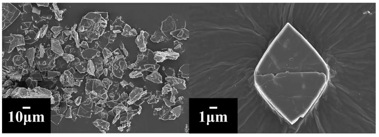
Figure 4. SEM images of the as-prepared [Zn4O(bdc)3]. The scales for the left and right SEM images were 10 μm and 1 μm, respectively.
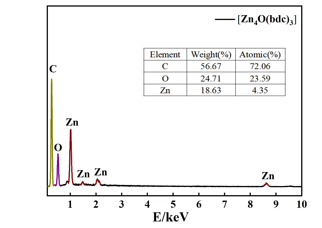
The EDS pattern of the as-prepared [Zn4O(bdc)3] is illustrated shown in Figure 5, in which the peaks assigned to C, O, and Zn elements are all explicitly presented. The atomic contents of C, O and Zn were about 72%, 23% and 4%, respectively, showing an atomic ratio of C:O:Zn 18:5:1, be different from the theoretical atomic ratio of pure [Zn4O(bdc)3] (Zn4O13C24H12) (C:O:Zn = 6:3.25:1), indicating that the as-prepared sample in this work was a quasi [Zn4O(bdc)3] rather than a pure [Zn4O(bdc)3]. In other words, the prepared sample was a new substance being various from the previously prepared [Zn4O(bdc)3].
3.2. Electrochemical Performance of ASS-LTO/Li
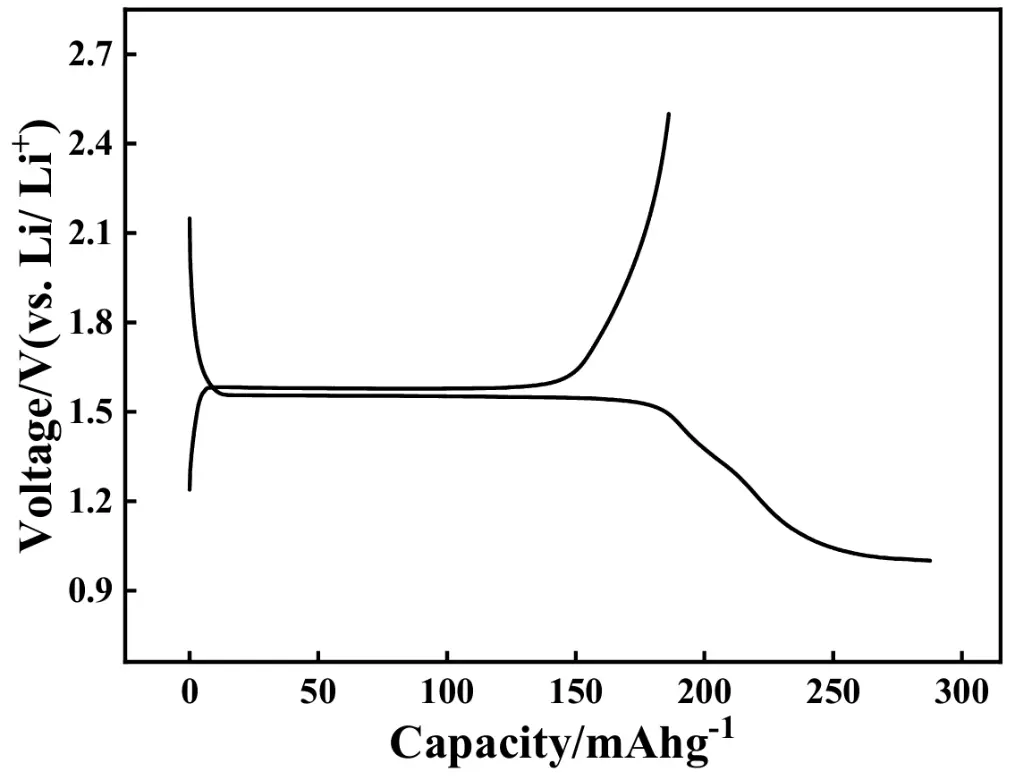
Figure 6 displays the initial charge-discharge curves of the ASS-LTO/Li battery at 0.2 C, in which the potential region is from 1.0 V to 2.5 V versus Li/Li+. Apparently, the voltage plateaus were respectively centered at around 1.59 V and 1.54 V in the charging and discharging process. The shape of the charging and discharging curves was almost identical to that of the conventional LTO/Li battery that was assembled by LTO, electrolyte solution, separator, electrolyte solution, and the metallic Li foil [47]. This result strongly indicated that the lithiation and delithiation process of the ASS-LTO/Li was the same as that of the traditional LTO/Li battery. In other words, the usage of the wetted quasi [Zn4O(bdc)3] as both the separator and the electrolyte did not affect the charging and discharging mechanism of the traditional LTO. The initial charge and discharge capacities of the ASS-LTO/Li at 0.2 C were 186 and 288 mAh·g−1, respectively, corresponding to a coulombic efficiency of about 66%. Obviously, both the charge and the discharge capacity have exceeded the theoretical capacity of the commercial LTO (175 mAh·g−1) [48,49], which substantially indicated that some part of the wetted quasi [Zn4O(bdc)3] has participated in the charging and discharging process of the newly prepared ASS-LTO/Li. Also, the discharge capacity value of 288 mAh·g−1 was significantly larger than that of pure LTO/Li [40] reported previously. That is, the initial charge and discharge performance of ASS-LTO/Li was comparable to that of the conventional LTO/Li battery.
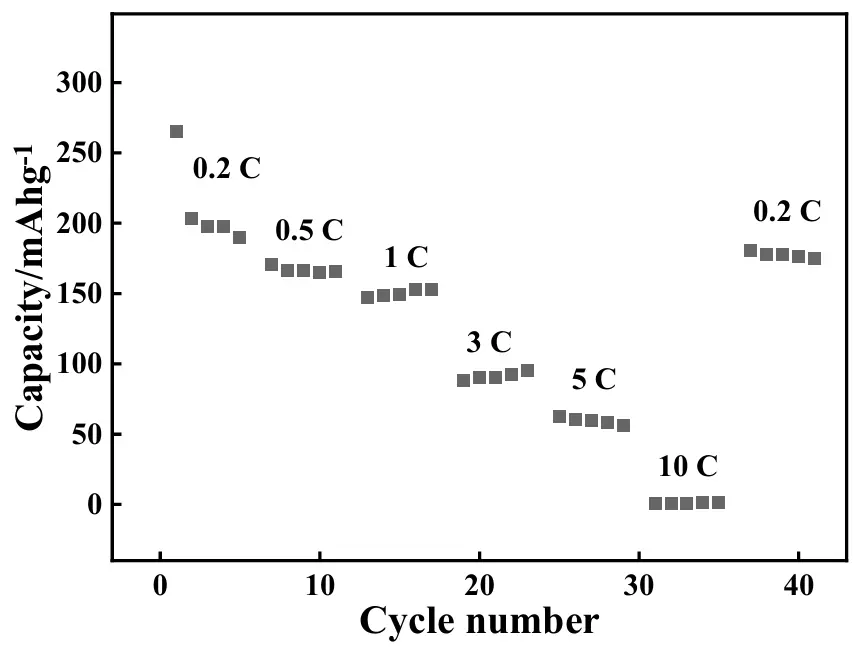
The rate capabilities of the newly developed ASS-LTO/Li were also measured, and the results are shown in Figure 7. In this experiment, the applied current rates were successively 0.2, 0.5, 1, 3, 5, and 10 C, and in each rate test, the ASS-LTO/Li was cycled for 5 cycles. Evidently, the discharge capacity decreased evidently with increasing applied current rates. The average discharge capacities at 0.2, 0.5, 1, 3, 5, and 10 C were, respectively, about 210, 167, 150, 91, 59, and 0.8 mAh·g−1. Interestingly, as the current rate was restored to be 0.2 C, as shown by the rightmost line, the average discharge capacity of ASS-LTO/Li was still recovered to be about 177 mAh·g−1, showing a relatively higher capacity retention rate of about 84%.
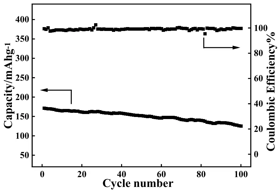
The relationship between the discharge capacity and cycling number for the as-prepared ASS-LTO/Li at 1 C is displayed in Figure 8 with the intention to study its long-term cycling performance. As can be seen, the initial discharge capacity of the ASS-LTO/Li at 1 C was 171 mAh·g−1, which decreased to 125 mAh·g−1 after 100 cycles, corresponding to a capacity retention of approximately 73%. It was worth noting that the discharge capacity value of 125 mAh·g−1 measured here was almost identical to that of the conventional LTO/Li (126 mAh·g−1) [50] (the conventional LTO/Li battery was assembled with LTO, electrolyte solution, separator, electrolyte solution and lithium foil, as has been well described in Ref. [40]). That is, the long-term cycling performance of the ASS-LTO/Li was commensurate with that of the traditional LTO/Li battery. In addition, as shown by the upper curve, the coulombic efficiency (CE) of the ASS-LTO/Li was maintained over 98% in the whole cycling test period, implying that almost no electric energy loss occurred in the total testing period.
To analyze the possible reasons endowing the ASS-LTO/Li an electrochemical performance decay, the following experiments were carried out. The FTIR spectra for the electrode material of LTO before and after the test of 100 cycles at 1 C are shown in Figure 9, in which pattern a and a′, respectively, correspond to the electrode material of LTO before and after the test of 100 cycles at 1 C. In pattern a, the absorption bands at 3440 cm−1 and 1611 cm−1 were all assigned to the stretching vibration of the –OH bonds, suggesting that a large number of –OH groups were immobilized on the surface of LTO [51]. The absorption band positioned at 1317 cm−1 was regarded as a typical band of LTO, attributed to the asymmetric stretching vibration of the Li–Ti–O structural unit [52]. The absorption bands at 774 cm−1 and 521 cm−1 were respectively ascribed to the asymmetric and symmetric stretching vibrations of the Ti–O bond [53], and the band at 439 cm−1 was due to the presence of the bending vibration of the Ti–O bond [54]. All in all, the FTIR shape of pattern a was almost identical to that of the pure LTO [52], which strongly demonstrated that no impurities were contained in the starting electrode material of LTO. For the electrode material of LTO after the test of 100 cycles at 1 C, as shown in pattern a′, four novel absorption bands, respectively centered at 1496, 1425, 860, and 667 cm−1 were clearly displayed in pattern a′. Generally, the absorption bands at 1496 cm−1 and 1425 cm−1 were attributed to the stretching vibration of C=C of the benzene ring [35], and the absorption bands at 860 cm−1 and 667 cm−1 were ascribed to the out-of-plane bending vibration of C–H bond of the benzene ring [46]. That is, the presence of the above four absorption bands in pattern a′ substantially indicated that the wetted quasi [Zn4O(bdc)3] was decomposed to some smaller molecules after the test of 100 cycles at 1 C, which was thought to be one main reason causing the electrochemical performance decay of the ASS-LTO/Li.
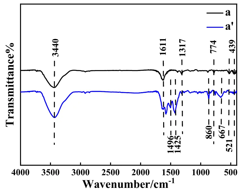
Figure 9. FTIR spectra for the electrode material of LTO before (pattern a) and after (pattern a′) the test of 100 cycles at 1 C.
The XRD patterns, including the standard XRD pattern of LTO, of the electrode material of LTO before and after the test of 100 cycles at 1 C are given in Figure 10. For pattern a, the characteristic diffraction peaks of LTO were all clearly displayed, that is, the diffraction peaks located at 2θ of 18.5°, 36.0°, 43.8°, 47.8°, 57.9°, 63.5° and 66.8° were respectively assigned to the (111), (311), (400), (331), (511), (440), and (531) crystallographic plane of Li4Ti5O12 (JCPDS No. 75-1602) [55], indicating that no other crystal substances were contained in the starting electrode material of LTO. Apparently, the XRD pattern for LTO after the long-term test, not only in terms of diffraction peak position but also with regard to the diffraction peak intensity ratios, was nearly the same as that of the starting electrode material of LTO, which substantially indicated that the crystal structure of LTO was not destroyed in the 1 C-rated 100 cycle test.
The CV (cyclic voltammetry) curves of the ASS-LTO/Li before (curve a) and after (curve a′) the test of 100 cycles at 1 C are given in Figure 11, in which the voltage range is from 1.0 V to 2.5 V, and the potential scanning rate is 1 mV·s−1. Evidently, the CV curve shape of curve a was very similar to that of the pure LTO [40,56], that is, the redox peaks in curve a corresponded to the following electrode reactions [57], Li4Ti5O12 + xLi+ + xe−↔Li4+xTi5O12. That is, for curve a, the electrochemical oxidation peak at 1.8 V corresponded to the extraction of Li+ from LTO, correspondingly, and the electrochemical reduction peak at about 1.3 V was assigned to the insertion of Li+ into LTO. In the case of curve a′, although an electrochemical oxidation and an electrochemical reduction peak also, respectively, emerged in the positive potential scanning and negative potential scanning, both the oxidation and reduction peak current attenuated greatly as compared to the case of curve a, for example, the electrochemical oxidation peak current of curve a (2.0 mA) was significantly higher than that of curve a′ (0.7 mA), which strongly indicated that the extraction rate of Li+ from LTO before the test of 100 cycles at 1 C was greatly faster than that occurring after the test [58]. In addition, the CV peak area of curve a was dramatically larger than that of curve a′, which strongly indicated that more amount of Li+ was transferred in LTO before the test of the 100 cycles at 1 C, since the CV peak area was generally proportional to the amount of ions/electrons transferred in the electrode reaction [59].
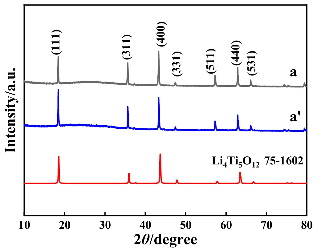
Figure 10. XRD patterns for the electrode material of LTO before (pattern a) and after (pattern a′) the test of 100 cycles at 1 C where the standard XRD pattern of LTO is also presented.
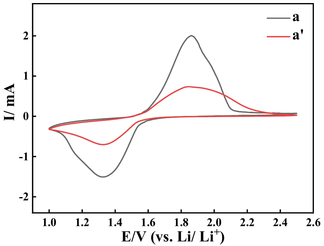
Figure 11. CV curves of the ASS-LTO/Li before (curve a) and after (curve a′) the test of 100 cycles at 1 C.
The Nyquist plots of the ASS-LTO/Li before (curve a) and after (curve a′) the test of 100 cycles at 1 C are illustrated in Figure 12. As shown by curve a, a semicircle appearing in the higher frequency region was followed by a sloped line appearing in the relatively lower frequency region. Interestingly, after the test of 100 cycles at 1 C, a similar curve, also constructed by a semicircle and a sloped line, was displayed. Generally, the diameter of the semicircle was tantamount to the value of the charge transfer resistance (Rct). Therefore, before the long-term test, the value of Rct was as low as about 33 Ω, which was augmented to around 58 Ω after the long-term test of 100 cycles at 1 C.
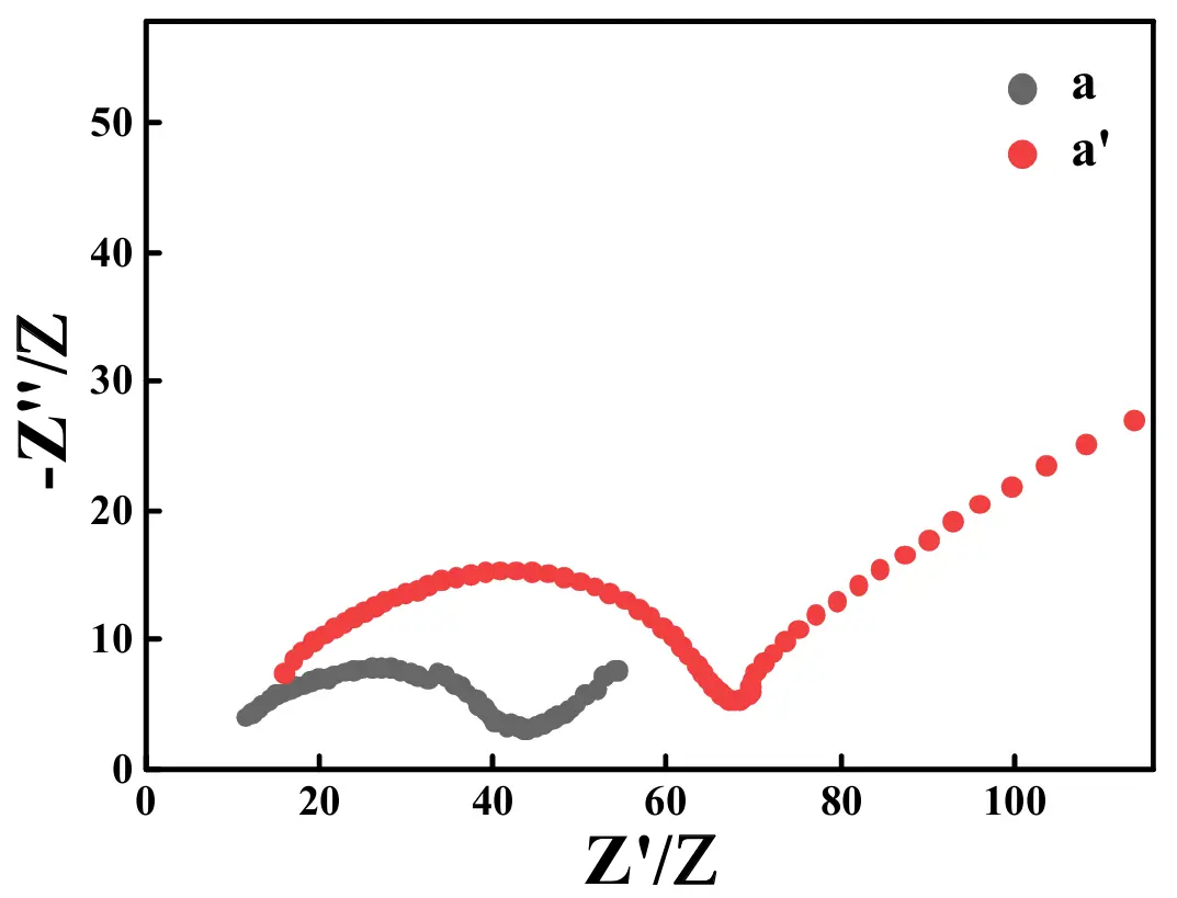
Figure 12. Nyquist plots of the ASS-LTO/Li before (curve a) and after (curve a′) the test of 100 cycles at 1 C.
3.3. Electrochemical Performance of ASS-Gr/Li
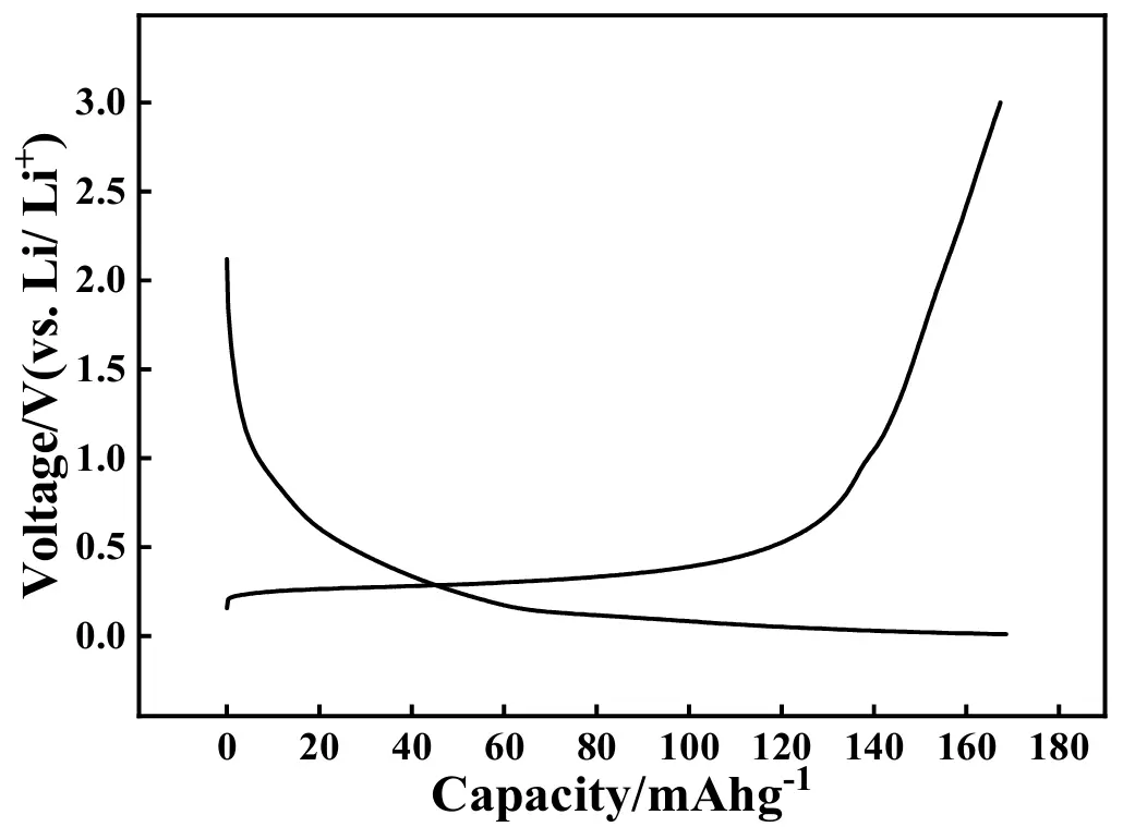
To expand the application scope of the prepared quasi [Zn4O(bdc)3], a graphite/Li battery that contained a graphite electrode, the as-prepared quasi [Zn4O(bdc)3], and a metallic Li foil was also assembled, which was denoted as ASS-Gr/Li. The initial charge-discharge profiles of ASS-Gr/Li at 0.2 A·g−1 are shown in Figure 13, in which the potential range was from 0.01 to 3.0 V versus Li/Li+. In the charging curve, a sloped voltage plateau appeared in the potential region ranging from 0.19 V to 0.45 V, which was followed by a nearly vertical line emerging in the potential limit ranging from 0.65 V to 3.0 V. Correspondingly, in the discharging curve, a vertical line appeared in the potential range from 2.1 V to 1.0 V, which was followed by a gentle voltage plateau appearing in the potential region ranging from 0.12 V to 0.01 V. Summarily, the shape of the curves shown in Figure 13 was almost identical to that of the pure graphite electrode [60]. That is to say, for the battery of ASS-Gr/Li, graphite, rather than the newly prepared [Zn4O(bdc)3], was still the main substance to extract/insert Li+. The initial charge and discharge capacities of the ASS-Gr/Li at 0.2 A·g−1 were 166 and 169 mAh·g−1, respectively, corresponding to a coulombic efficiency of about 98.2%, a value close to 100%. Frankly speaking, the initial discharge capacity of 169 mAh·g−1 was lower than that of conventional graphite batteries [61]; therefore, more work is required to improve the initial charge and discharge performance of the newly assembled ASS-Gr/Li in the near future.
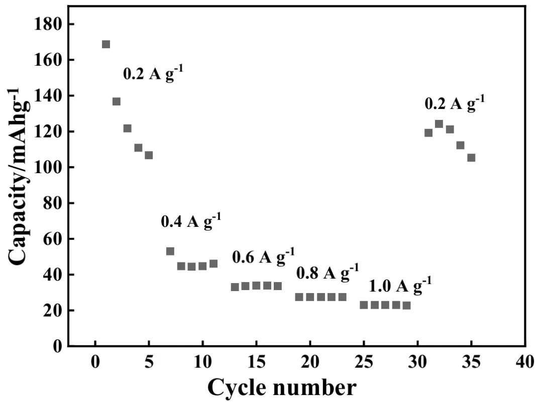
The rate performance of ASS-Gr/Li was also measured, and the results are shown in Figure 14. In the rate test, the applied current density values were successively 0.2, 0.4, 0.6, 0.8, and 1.0 A·g−1, and in each rate test, the battery of ASS-Gr/Li was cycled for 5 times. Evidently, the discharge capacity of ASS-Gr/Li decreased markedly with increasing the applied current density. The average discharge capacity values of ASS-Gr/Li at 0.2, 0.4, 0.6, 0.8, and 1.0 A·g−1 were 129, 47, 34, 27, and 23 mAh·g−1, respectively. Interestingly, as the applied current density was returned to 0.2 A·g−1, the average discharge capacity of ASS-Gr/Li was still retained to be about 116 mAh·g−1, showing a capacity retention rate of 90%. Apparently, in the rate tests, the average discharge capacity values of the ASS-Gr/Li were all lower than 50 mAh·g−1 once the applied current density was higher than 0.4 A·g−1, showing a relatively poor rate capability.
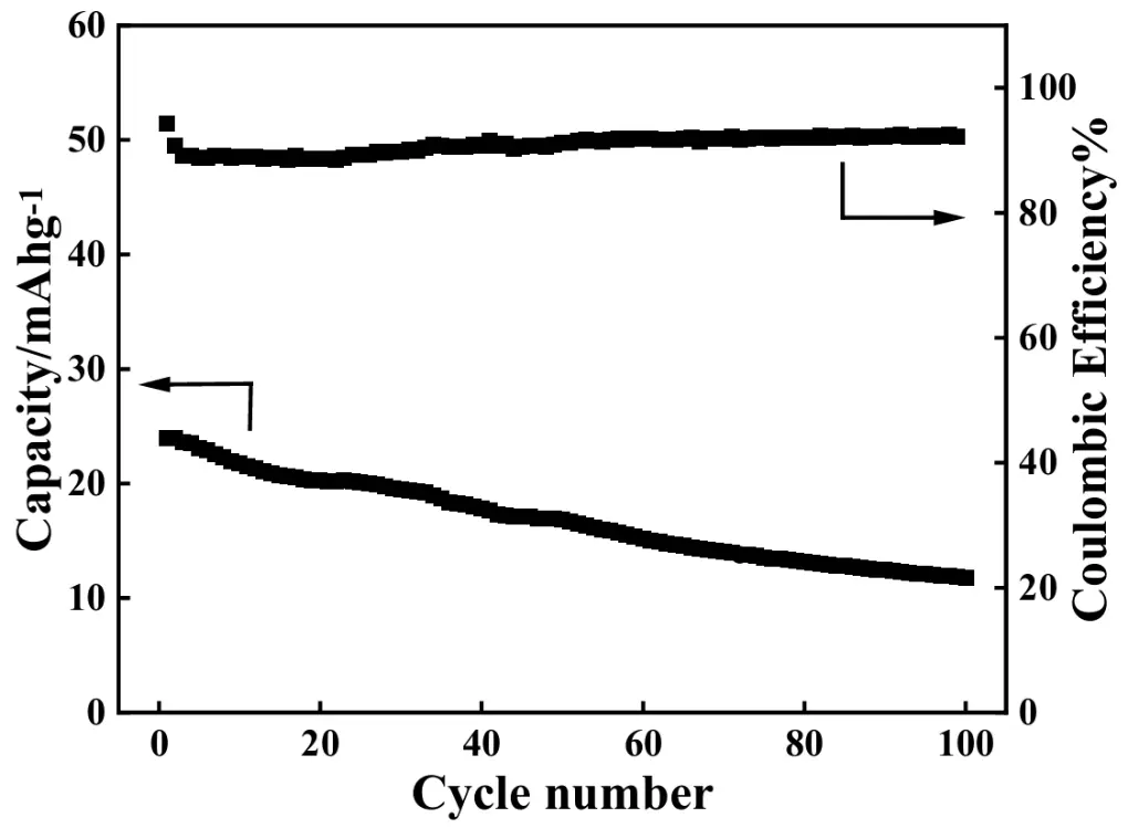
The cycling performance of ASS-Gr/Li at 1.0 A·g−1 for 100 cycles was also studied, and the results are shown in Figure 15. As can be observed, the discharge capacity of the ASS-Gr/Li decreased gradually with increasing cycling number. For example, the initial discharge capacity of the ASS-Gr/Li was 24 mAh·g−1, which was reduced to about 12 mAh·g−1 after 100 cycles, corresponding to a capacity retention ratio of about 50%. Meanwhile, as shown by the upper curve in Figure 15, the coulombic efficiency (CE) of the ASS-Gr/Li in the whole cycling test was always higher than 90%, which substantially indicated that the electric energy loss occurred in the cycling period was negligible.
To analyze the possible reasons endowing the as-prepared ASS-Gr/Li an evident decay in the electrochemical performance, the following experiments before and after the test of 100 cycles at 1.0 A·g−1 were systematically conducted. Figure 16 shows the FTIR spectra of the electrode material of graphite before (pattern b) and after (pattern b′) the test of 100 cycles at 1.0 A·g−1. No evident difference between pattern b and pattern b′ was found which effectively indicated that the chemical components of the graphite were not altered even after the 1.0 A·g−1 100 cycle test, that is, the broad absorption band at 3432 cm−1 was attributed to the stretching vibration of –OH group [51], and the absorption band at 1627 cm−1 was stemmed from the bending vibration of C–OH [62]. Additionally, the intensity of the band at 3432 cm−1 for pattern b was obviously higher than that of the band for pattern b′, which strongly indicated that the polarity of graphite before the long-term test was greater than that of graphite after the long-term test. Generally speaking, the graphite with a higher polarity was conducive to the insertion and extraction process of polar ions of Li+ [63]. As a result, the electrode material of graphite delivered a better electrochemical performance during the beginning period of the long-term test.
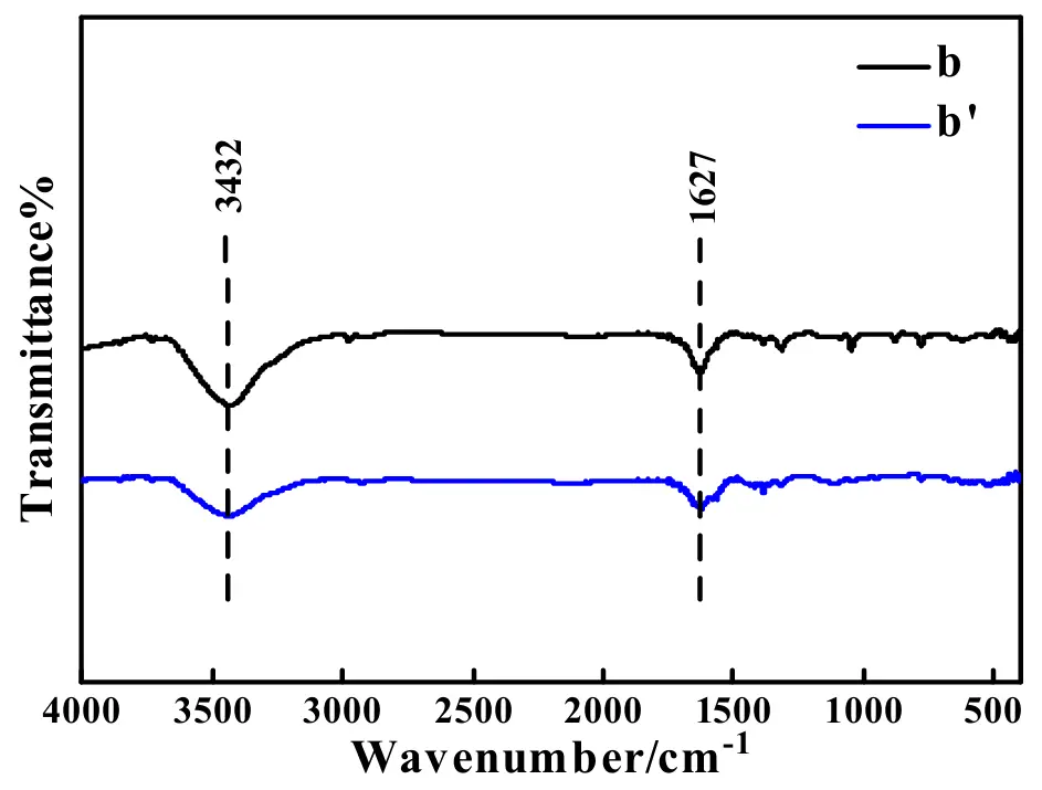
Figure 16. FTIR patterns for the electrode material of graphite before (pattern b) and after (pattern b′) the test of 100 cycles at 1.0 A·g−1.
Figure 17 shows the XRD patterns of the electrode material of graphite before (pattern b) and after (pattern b′) the test of 100 cycles at 1.0A·g−1, in which the standard XRD pattern of graphite is also presented. Prior to the test of 100 cycles at 1.0 A·g−1, as shown by pattern b, the diffraction peaks observed at 2θ of 26.5° and 54.7° were, respectively, indexed to the (002) and (004) crystal planes of graphite (JCPDS No. 8-415) [64]. The presence of the sharper diffraction peaks in pattern b strongly implied that the crystallinity of the graphite before the test was high, which was thought to be very favorable to the directional shifting of ions to some degree [65]. After the experiment of 100 cycles at 1.0 A·g−1, as shown by pattern b′, only a very small diffraction peak at 26.5° was displayed, and the diffraction peak at 54.7° vanished totally. The comparison of the XRD patterns for graphite before and after the long-term test strongly indicated that graphite particles with a higher crystallinity have been converted into graphite particles with a rather lower crystallinity after the test of 100 cycles at 1.0 A·g−1, which probably was a reason providing ASS-Gr/Li an evident cycling performance decay [66].
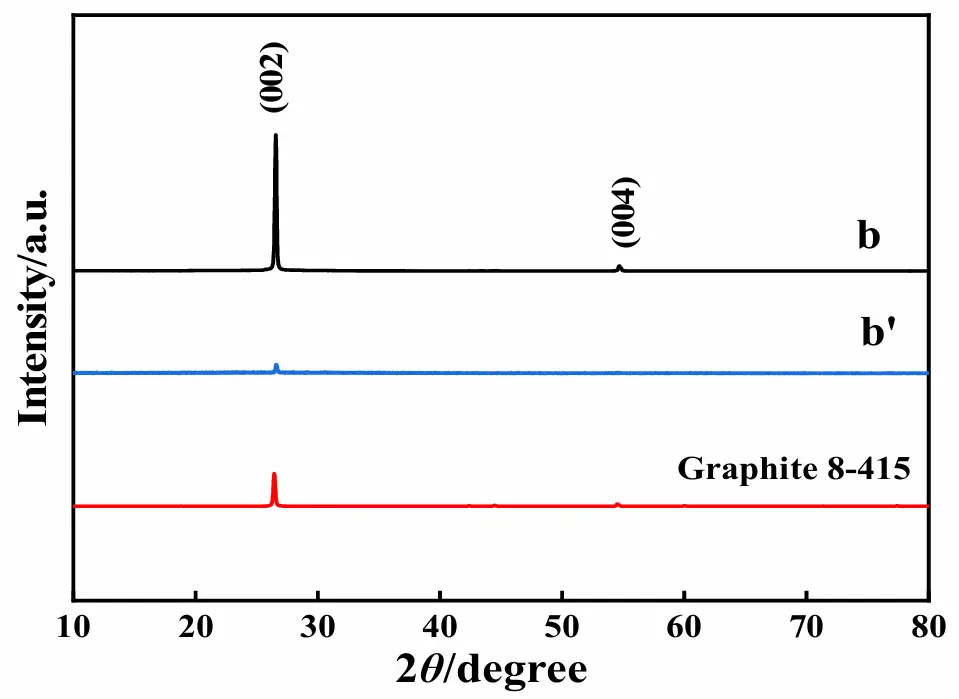
Figure 17. XRD patterns for graphite before (pattern b) and after (pattern b′) the test of 100 cycles at 1.0 A·g−1.
The CV (cyclic voltammetry) curves of the ASS-Gr/Li battery before (curve b) and after (curve b′) the test of 100 cycles at 1.0 A·g−1 are shown in Figure 18, in which the potential scan rate was 1 mV·s−1, and the potential range was from 0.01 V to 3.00 V. In curve b, a sharp electrochemical oxidation CV peak (also called as anodic peak) accompanied by a shoulder-shaped small peak (at about 0.26 V), was displayed at about 0.32 V, which was generally due to the deintercalation of Li+ from the graphite [67,68]. Correspondingly, an electrochemical reduction CV peak (also called as cathodic peak), accompanied by a shoulder-shaped small peak (at about 0.10 V) was exhibited at about 0.01 V, which was usually attributed to the intercalation of Li+ into the graphite material [69]. The CV curve shape of curve b was very similar to that of the pure graphite electrode [70], which substantially indicated that graphite, instead of the newly prepared quasi [Zn4O(bdc)3], was the main lithium storage material. After the long-term test, as shown by curve b′, only an anodic CV peak at 0.44 V and a cathodic CV peak at about 0.01 V were displayed in the CV curve. The presence of both anodic and cathodic peaks in the CV curves strongly indicated that the graphite electrode still had the ability to undergo both the insertion and extraction processes of Li+. Evidently, compared to the area of the CV peak (curve b) before the long-term test, the area of the CV peak (curve b′) shown after the long-term test was significantly smaller, which effectively demonstrated that the amount of Li+ transferred in graphite after the long-term test was less than that occurring before the long-term test. That is, with increasing the cycling number, for the newly prepared ASS-Gr/Li, the lithium storage capacity of graphite dramatically decreased, probably being one major reason causing an evident electrochemical performance degeneration of ASS-Gr/Li.
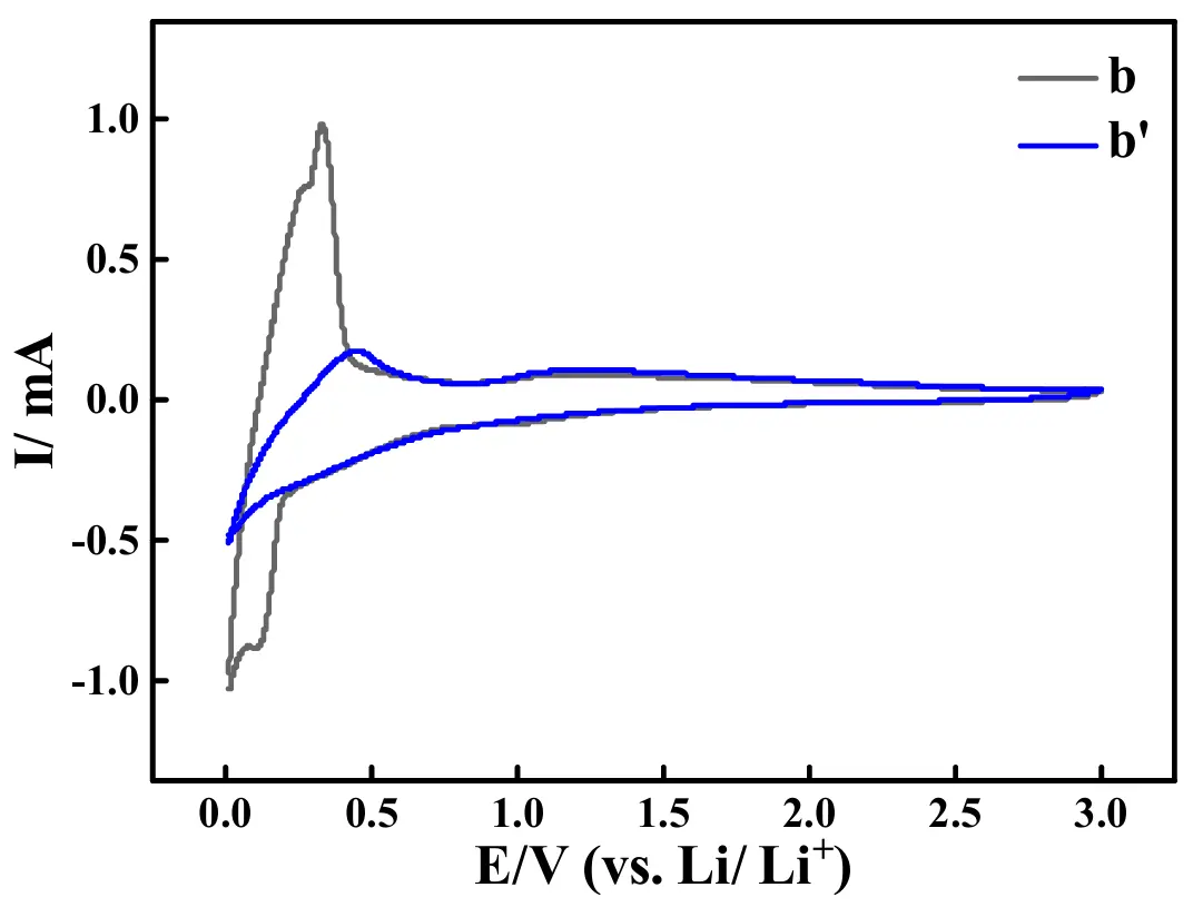
Figure 18. CV curves of the ASS-Gr/Li before (curve b) and after (curve b′) the test of 100 cycles at 1.0 A·g−1.
The Nyquist plots of the ASS-Gr/Li before (plot b) and after (plot b′) the test of 100 cycles at 1.0 A·g−1 are illustrated in Figure 19. Apparently, the change trend of the Nyquist plot shape for ASS-Gr/Li was almost the same as that of ASS-LTO/Li, that is, prior to the long-term test, the Rct value of ASS-Gr/Li was as low as about 40 Ω, which was increased to be about 178 Ω after the test of 100 cycles at 1.0 A·g−1. It was worth noting that the Rct value of 40 Ω for ASS-Gr/Li was significantly lower than that of the graphite-derived material of mild expanded graphite microspheres (MEGMs) [71]. Therefore, the greatly enlarged Rct was analyzed to be one main reason ruining the long-term electrochemical performance of the newly prepared ASS-Gr/Li.
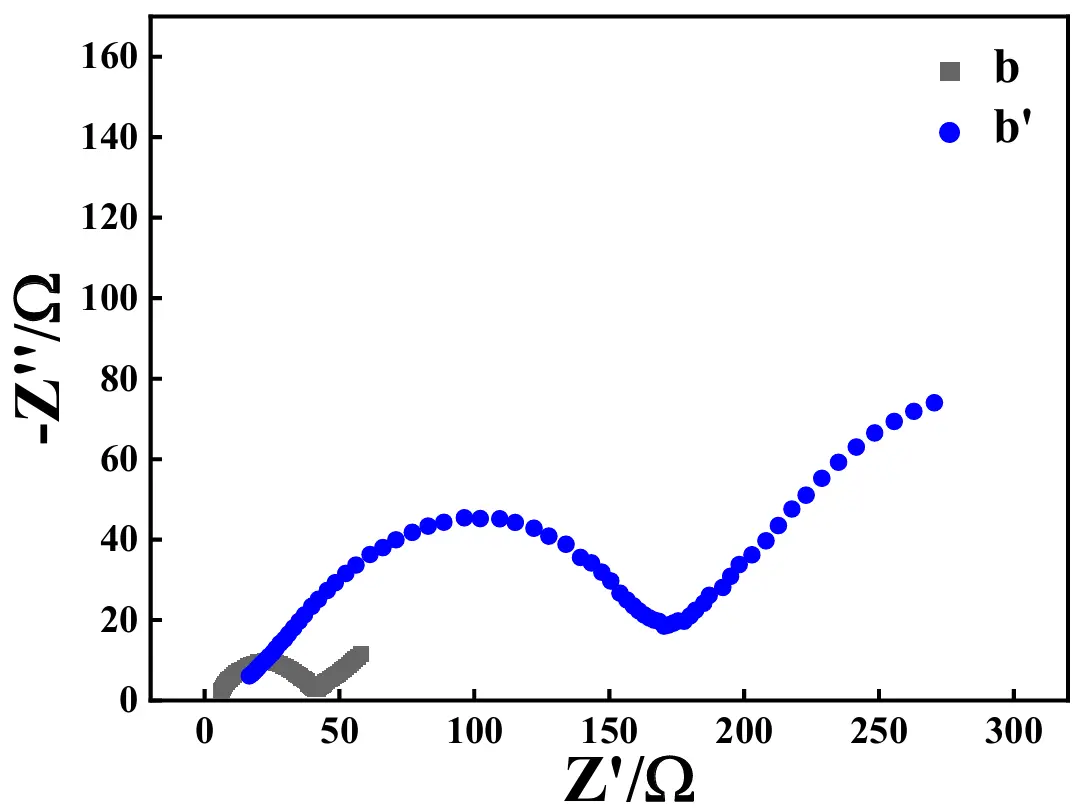
Figure 19. Nyquist plots of the ASS-Gr/Li before (plot b) and after (plot b′) the test of 100 cycles at 1.0 A·g−1.
4. Conclusions
In this work, two kinds of all-solid-state lithium batteries, namely, ASS-LTO/Li and ASS-Gr/Li, were prepared, in which a wetted quasi MOF-5 containing Zn2+, O−, benzene ring, and C=C, namely, quasi [Zn4O(bdc)3] was employed not only as a separator but also as a solid-state electrolyte. To the best of our knowledge, this is the first time to use a MOF as both a separator and a solid-state electrolyte to assemble solid-state lithium batteries of LTO/Li and Gr/Li. The absence of a battery separator and electrolyte solution was the greatest advantage of the newly prepared lithium batteries of both ASS-LTO/Li and ASS-Gr/Li, which enabled this work to be very meaningful to the further development of all-solid-state lithium batteries. Encouragingly, for the newly prepared ASS-LTO/Li, its initial discharge capacity at 0.2 C was as high as 286.4 mAh·g−1, and the discharge capacity of ASS-LTO/Li at 1 C after 100 cycles was still close to 125 mAh·g−1. A characterization comparison before and after the test of the 100 cycles at 1 C revealed that the greatly attenuated CV peak area and the evidently increased Rct value were the main reasons endowing as-prepared ASS-LTO/Li an evident electrochemical performance decay. In the case of the ASS-Gr/Li battery, its initial discharge capacity at 0.2 A·g−1 was as high as about 169 mAh·g−1. Unfortunately, as the applied current was 1.0 A·g−1, the discharge capacity value of ASS-Gr/Li decreased from 24 mAh·g−1 at the first cycle to 12 mAh·g−1 at the 100th cycle, showing a rather poor long-term cycling performance. Although the electrochemical performances of ASS-LTO/Li and ASS-Gr/Li, especially that of ASS-Gr/Li, were not significant, this work was a pioneering work either from the perspective of [Zn4O(bdc)3] MOF-5 utilization or in terms of the not usage of both battery separator and electrolyte solution. All in all, this work was a groundbreaking work, being of far-reaching significance to the exploration all-solid-state lithium batteries.
Author Contributions
Conceptualization, K.D.; Methodology, K.D.; Software, J.B.; Validation, Q.Z., M.N. and W.S.; Formal Analysis, Y.C.; Investigation, Y.C.; Resources, H.W.; Data Curation, Y.C.; Writing—Original Draft Preparation, K.D.; Writing—Review & Editing, K.D. All authors have read and agreed to the published version of the manuscript.
Ethics Statement
Not applicable.
Informed Consent Statement
Not applicable.
Data Availability Statement
The data that support the findings of this study are available from the corresponding author upon reasonable request.
Funding
This research was funded by the Hebei Natural Science Foundation (B2024205035) and Innovation Ability Improvement Project of Hebei province (225A4402D) and The Innovation Capability Improvement Plan Project of Hebei Province (22567604H).
Declaration of Competing Interest
The authors declare that they have no known competing financial interests or personal relationships that could have appeared to influence the work reported in this paper.
References
- Zhang R, Wang C, Zou P, Lin R, Ma L, Yin L, et al. Compositionally complex doping for zero-strain zero-cobalt layered cathodes. Nature 2022, 610, 67–73. DOI:10.1038/s41586-022-05115-z [Google Scholar]
- Francis CFJ, Kyratzis IL, Best AS. Lithium-ion battery separators for ionic-liquid electrolytes: A review. Adv. Mater. 2020, 32, 1904205. DOI:10.1002/adma.201904205 [Google Scholar]
- Wei Y, Wang M, Zhang M, Cai T, Huang Y, Xu M. Advancements, Challenges, and Future Trajectories in Advanced Battery Safety Detection. Electrochem. Energy Rev. 2025, 8, 10. DOI:10.1007/s41918-025-00245-0 [Google Scholar]
- Li L, Liu J, Li L, Chen J, Liu J, Zhou R, et al. Pentafluorophenyl diethoxy phosphate: An electrolyte additive for high-voltage cathodes of lithium-ion batteries. J. Energy Storage 2024, 87, 111364. DOI:10.1016/j.est.2024.111364 [Google Scholar]
- Zhou L, Zuo TT, Kwok CY, Kim SY, Assoud A, Zhang Q, et al. High areal capacity, long cycle life 4 V ceramic all-solid-state Li-ion batteries enabled by chloride solid electrolytes. Nat. Energy 2022, 7, 83–93. DOI:10.1038/s41560-021-00952-0 [Google Scholar]
- Shalaby MS, Alziyadi MO, Gamal H, Hamdy S. Solid-state lithium-ion battery: The key components enhance the performance and efficiency of anode, cathode, and solid electrolytes. J. Alloys Compd. 2023, 969, 172318. DOI:10.1016/j.jallcom.2023.172318 [Google Scholar]
- Men M, Wu J, Liu G, Zhang J, Zhang N, Yao X. Sulfide solid electrolyte synthesized by liquid phase approach and application in all-solid-state lithium batteries. Acta Phys. Chim. Sin. 2025, 41, 100004. DOI:10.3866/PKU.WHXB202309019 [Google Scholar]
- Ramakumar S, Deviannapoorani C, Dhivya L, Shankar LS, Murugan R. Lithium garnets: Synthesis, structure, Li+ conductivity, Li+ dynamics and applications. Prog. Mater Sci. 2017, 88, 325–411. DOI:10.1016/j.pmatsci.2017.04.007 [Google Scholar]
- Chang Q, Wei A, Li W, Bai X, Zhang L, He R, et al. Structural and electrochemical characteristics of Al2O3-modified LiNi0.5Mn1.5O4 cathode materials for lithium-ion batteries. Ceram. Int. 2019, 45, 5100–5110. DOI:10.1016/j.ceramint.2018.11.213 [Google Scholar]
- Jin F, Ellingsen IS, Fadillah L, Nguyen QH, Bratlie HR, Knez D, et al. LiBF4-Derived Coating on LiCoO2 for 4.5 V Operation of Li6PS5Cl-Based Solid-State Batteries. Energy Environ. Mater. 2025, 8, e70047. DOI:10.26434/chemrxiv-2025-2sqt6 [Google Scholar]
- Kaewmala S, Wiriya N, Chantrasuwan P, Yordsri V, Limphirat W, Muhammad S, et al. A multiscale investigation elucidating the structural complexities and electrochemical properties of layered–layered composite cathode materials synthesized at low temperatures. Phys. Chem. Chem. Phys. 2020, 22, 5439–5448. DOI:10.1039/C9CP06165G [Google Scholar]
- Belgibayeva A, Nagashima T, Taniguchi I. Synthesis of LiCoPO4/C nanocomposite fiber mats as free-standing cathode materials for lithium-ion batteries with improved electrochemical properties. Electrochim. Acta 2022, 419, 140400. DOI:10.1016/j.electacta.2022.140400 [Google Scholar]
- Rajammal K, Numan A, Sivakumar D. Enhanced electrochemical properties of Al2O3-coated LiNiPO4 cathode materials for lithium-ion batteries. Ionics 2024, 30, 7929–7938. DOI:10.1007/s11581-024-05894-7 [Google Scholar]
- Calpa M, Rosero-Navarro NC, Miura A, Tadanaga K. Argyrodite solid electrolyte-coated graphite as anode material for all-solid-state batteries. J. Sol-Gel Sci. Technol. 2022, 101, 8–15. DOI:10.1007/s10971-021-05634-7 [Google Scholar]
- Orue Mendizabal A, Gomez N, Aguesse F, López-Aranguren P. Designing spinel Li4Ti5O12 electrode as anode material for poly(ethylene) oxide-based solid-state batteries. Materials 2021, 14, 1213. DOI:10.3390/ma14051213 [Google Scholar]
- Dou F, Shi L, Chen G, Zhang D. Silicon/carbon composite anode materials for lithium-ion batteries. Electrochem. Energy Rev. 2019, 2, 149–198. DOI:10.1007/s41918-018-00028-w [Google Scholar]
- Shen X, Liu H, Cheng XB, Yan C, Huang JQ. Beyond lithium ion batteries: Higher energy density battery systems based on lithium metal anodes. Energy Storage Mater. 2018, 12, 161–175. DOI:10.1016/j.ensm.2017.12.002 [Google Scholar]
- Ai S, Wu X, Wang J, Li X, Hao X, Meng Y. Research progress on solid-state electrolytes in solid-state lithium batteries: Classification, ionic conductive mechanism, interfacial challenges. Nanomaterials 2024, 14, 1773. DOI:10.3390/nano14221773 [Google Scholar]
- Chen Y, Qian J, Wang K, Li L, Wu F, Chen R. Cutting-Edge Developments at the Interface of Inorganic Solid-State Electrolytes. Adv. Mater. 2025, 37, 2502653. DOI:10.1002/adma.202502653 [Google Scholar]
- Li ZY, Li Z, Fu JL, Guo X. Sodium-ion conducting polymer electrolytes. Rare Met. 2023, 42, 1–16. DOI:10.1007/s12598-022-02132-9 [Google Scholar]
- Paengson S, Pilasuta P, Mori D, Seetawan T. Effect of Sr and Ta co-substitution on microstructure and ionic conductivity of cubic-Li0.5La0.5TiO3 electrolyte for applications in Li batteries. J. Alloys Compd. 2024, 979, 173512. DOI:10.1016/j.jallcom.2024.173512 [Google Scholar]
- Wang Y, Wang Z, Wu D, Niu Q, Lu P, Ma T, et al. Stable Ni-rich layered oxide cathode for sulfide-based all-solid-state lithium battery. eScience 2022, 2, 537–545. DOI:10.1016/j.esci.2022.06.001 [Google Scholar]
- Zhang S, Zhao F, Su H, Zhong Y, Liang J, Chen J, et al. Cubic Iodide LixYI3+x Superionic Conductors through Defect Manipulation for All-Solid-State Li Batteries. Angew. Chem. Int. Ed. 2024, 63, e202316360. DOI:10.1002/anie.202316360 [Google Scholar]
- Martinez-Ibañez M, Sanchez-Diez E, Qiao L, Zhang Y, Judez X, Santiago A, et al. Unprecedented improvement of single Li-Ion conductive solid polymer electrolyte through salt additive. Adv. Funct. Mater. 2020, 30, 2000455. DOI:10.1002/adfm.202000455 [Google Scholar]
- Liu K, Xie Y, Ding T, Guo C, Guo P, Liu J, et al. High-Strength Ultrathin Solid-State Electrolyte with Ion-Rectifying Honeycomb-Like Skeleton for Lithium Metal Batteries Free from External Pressure. Adv. Funct. Mater. 2025, 36, e11558. DOI:10.1002/adfm.202511558 [Google Scholar]
- Yao M, Ruan Q, Wang Y, Du L, Li Q, Xu L, et al. A Robust Dual-Polymer@Inorganic Networks Composite Polymer Electrolyte Toward Ultra-Long-Life and High-Voltage Li/Li-Rich Metal Battery. Adv. Funct. Mater. 2023, 33, 2213702. DOI:10.1002/adfm.202213702 [Google Scholar]
- Jiang Y, Zhao S, Xiao X, Pi J, Wang Y, Yi N, et al. Poly(benzoxazine)-Based Gel Polymer Electrolytes for Lithium Metal Batteries with Ultralong Lifespans. Angew. Chem. Int. Ed. 2025, 64, e202510997. DOI:10.1002/anie.202510997 [Google Scholar]
- Zhang X, Cheng S, Fu C, Yin G, Wang L, Wu Y, et al. Advancements and challenges in organic–inorganic composite solid electrolytes for all-solid-state lithium batteries. Nano-Micro Lett. 2025, 17, 2. DOI:10.1007/s40820-024-01498-y [Google Scholar]
- Song X, Zhang TH, Fan RZ, Biao J, Huang SH, Travaš-Sejdić J, et al. A composite solid-state electrolyte of high ionic-conductivity garnet-type Li6.5La3Zr1.5Ta0.1Nb0.4O12 filler in PEO matrix. Solid State Ionics 2023, 403, 116410. DOI:10.1016/j.ssi.2023.116410 [Google Scholar]
- Miao X, Wang H, Sun R, Wang C, Zhang Z, Li Z, et al. Interface engineering of inorganic solid-state electrolytes for high-performance lithium metal batteries. Energy Environ. Sci. 2020, 13, 3780–3822. DOI:10.1039/D0EE01435D [Google Scholar]
- Zhou D, Shanmukaraj D, Tkacheva A, Armand M, Wang G. Polymer electrolytes for lithium-based batteries: advances and prospects. Chem 2019, 5, 2326–2352. DOI:10.1016/j.chempr.2019.05.009 [Google Scholar]
- Wang C, Wang S, Liu X, Wu Y, Yu R, Duan H, et al. New insights into aliovalent substituted halide solid electrolytes for cobalt-free all-solid state batteries. Energy Environ. Sci. 2023, 16, 5136–5143. DOI:10.1039/D3EE01119D [Google Scholar]
- Niu Y, Wang Y, Zhang H. MOF in catalysis, sensing and energy storage applications. Nano Energy 2026, 147, 111598. DOI:10.1016/j.nanoen.2025.111598 [Google Scholar]
- Borah P, Roy S, Ahmaruzzaman M. Synergistic frameworks: Rationally designed dual MOF-on-MOF hybrid heterostructures for innovative next-gen applications. Appl. Mater. Today 2025, 47, 102967. DOI:10.1016/j.apmt.2025.102967 [Google Scholar]
- Dusabirane E, Nasr M, Fujii M, Shokry H. Enhanced room temperature greenhouse gases detection using MOF-5 and cobalt-doped MOF-5 thin films. J. Inorg. Organomet. Polym. Mater. 2025, 35, 3649–3664. DOI:10.1007/s10904-024-03483-9 [Google Scholar]
- Li J, Liu P, Chen Y, Zhou J, Li J, Yang J, et al. A customized hydrophobic porous shell for MOF-5. J. Am. Chem. Soc. 2023, 145, 19707–19714. DOI:10.1021/jacs.3c04831 [Google Scholar]
- Razavi L, Raissi H, Hashemzehi O, Farzad F. Significantly enhanced performance for phenol compounds removal by MOF-5 nano-composite via its surface modification. npj Clean Water 2024, 7, 44. DOI:10.1038/s41545-024-00338-1 [Google Scholar]
- Zarghmapour S, Khodadadi A, Rahimpoor R, Mengelizadeh N, Balarak D. Photocatalytic activation of peroxymonosulfate by MOF-5@ Fe3O4 in the removal of acid blue 113 from polluted water. Results Eng. 2025, 25, 104426. DOI:10.1016/j.rineng.2025.104426 [Google Scholar]
- Sakamaki Y, Tsuji M, Heidrick Z, Watson O, Durchman J, Salmon C, et al. Preparation and applications of metal–organic frameworks (MOFs): A laboratory activity and demonstration for high school and/or undergraduate students. J. Chem. Educ. 2020, 97, 1109–1116. DOI:10.1021/acs.jchemed.9b01166 [Google Scholar]
- Ding K, Li M, Li W, Bai Y, Liang X, Wu M, et al. Calcining the mixture having lithium titanate (LTO) and CuBr in air to significantly boost the electrochemical performance of the commercial LTO. J. Power Sources 2025, 625, 235691. DOI:10.1016/j.jpowsour.2024.235691 [Google Scholar]
- Ding K, Shi F, Zhang Z, Li B, Di M, Yan M, et al. Promoting Effect of Cobblestone-shaped CuI Nanoparticles Immobilized on the Copper Foil Surface on the Electrochemical Performance of the Conventional Graphite Electrode. Int. J. Electrochem. Sci. 2022, 17, 220965. DOI:10.20964/2022.09.61 [Google Scholar]
- Saeed-Ul-Hassan M, Ehtisham M, Badawi AK, Khan AM, Khan RA, Ismail B. A comparative study of moisture adsorption on GO, MOF-5, and GO/MOF-5 composite for applications in atmospheric water harvesting. Nanoscale Adv. 2024, 6, 3668–3679. DOI:10.1039/D4NA00150H [Google Scholar]
- Hu Y, Yang H, Wang R, Duan M. Fabricating Ag@ MOF-5 nanoplates by the template of MOF-5 and evaluating its antibacterial activity. Colloids Surf. A 2021, 626, 127093. DOI:10.1016/j.colsurfa.2021.127093 [Google Scholar]
- Lee S, Wang G, Ji N, Zhang M, Wang D, Sun L, et al. Synthesis, characterizations and kinetics of MOF-5 as herbicide vehicle and its controlled release in PVA/ST biodegradable composite membranes. Z. Anorg. Chem. 2022, 648, e202100252. DOI:10.1002/zaac.202100252 [Google Scholar]
- Cheng S, Li Y, Yu Z, Gu R, Wu W, Su Y. Waste PET-derived MOF-5 for high-efficiency removal of tetracycline. Sep. Purif. Technol. 2024, 339, 126490. DOI:10.1016/j.seppur.2024.126490 [Google Scholar]
- Wang S, Xie X, Xia W, Cui J, Zhang S, Du X. Study on the structure activity relationship of the crystal MOF-5 synthesis, thermal stability and N2 adsorption property. High Temp. Mater. Process. 2020, 39, 171–177. DOI:10.1515/htmp-2020-0034 [Google Scholar]
- Li L, Jia X, Zhang Y, Qiu T, Hong W, Jiang Y, et al. Li4Ti5O12 quantum dot decorated carbon frameworks from carbon dots for fast lithium ion storage. Mater. Chem. Front. 2019, 3, 1761–1767. DOI:10.1039/C9QM00259F [Google Scholar]
- Rajagopalan B, Kim B, Hur SH, Yoo IK, Chung JS. Redox synthesis of poly (p–phenylenediamine)–reduced graphene oxide for the improvement of electrochemical performance of lithium titanate in lithium–ion battery anode. J. Alloys Compd. 2017, 709, 248–259. DOI:10.1016/j.jallcom.2017.03.166 [Google Scholar]
- Zhu J, Duan R, Zhang Y, Zhu J. A facial solvothermal reduction route for the production of Li4Ti5O12/graphene composites with enhanced electrochemical performance. Ceram. Int. 2016, 42, 334–340. DOI:10.1016/j.ceramint.2015.08.115 [Google Scholar]
- Wu X, Liang X, Zhang X, Lan L, Li S, Gai Q. Structural evolution of plasma sprayed amorphous Li4Ti5O12 electrode and ceramic/polymer composite electrolyte during electrochemical cycle of quasi-solid-state lithium battery. J. Adv. Ceram. 2021, 10, 347–354. DOI:10.1007/s40145-020-0447-9 [Google Scholar]
- Odziomek M, Chaput F, Rutkowska A, Świerczek K, Olszewska D, Sitarz M, et al. Hierarchically structured lithium titanate for ultrafast charging in long-life high capacity batteries. Nat. Commun. 2017, 8, 15636. DOI:10.1038/ncomms15636 [Google Scholar]
- Johnson K, Pushparajan J, Anjana PM, Gopinadh SV, Anoopkumar V, Peddinti VP, et al. Synthesis, characterisation and electrochemical evaluation of lithium titanate anode for lithium ion cells. Inorg. Chem. Commun. 2022, 137, 109188. DOI:10.1016/j.inoche.2021.109188 [Google Scholar]
- Al-Muntaser AA, Pashameah RA, Tarabiah AE, Alzahrani E, AlSubhi SA, Saeed A, et al. Structural, morphological, optical, electrical and dielectric features based on nanoceramic Li4Ti5O12 filler reinforced PEO/PVP blend for optoelectronic and energy storage devices. Ceram. Int. 2023, 49, 18322–18333. DOI:10.1016/j.ceramint.2023.02.204 [Google Scholar]
- Xie Y, Hong X, Liu J, Le Z, Huang F, Qin Y, et al. Synthesis and electromagnetic properties of BaFe11.92(LaNd)0.04O19/titanium dioxide composites. Mater. Res. Bull. 2014, 50, 483–489. DOI:10.1016/j.materresbull.2013.11.022 [Google Scholar]
- Noerochim L, Prabowo RS, Widyastuti W, Susanti D, Subhan A, Idris NH. Enhanced high-rate capability of iodide-doped Li4Ti5O12 as an anode for lithium-ion batteries. Batteries 2023, 9, 38. DOI:10.3390/batteries9010038 [Google Scholar]
- Meng Q, Chen F, Hao Q, Li N, Sun X. Nb-doped Li4Ti5O12-TiO2 hierarchical microspheres as anode materials for high-performance Li-ion batteries at low temperature. J. Alloys Compd. 2021, 885, 160842. DOI:10.1016/j.jallcom.2021.160842 [Google Scholar]
- Zhang L, Zhang JD, Luo X, Long YF, Xue X, Yin Y, et al. Electrochemical performance of Li4Ti5O12 anode material synthesised using polyethylene glycol as a template agent. Ceram. Int. 2021, 47, 4729–4736. DOI:10.1016/j.ceramint.2020.10.042 [Google Scholar]
- Ding K, Qu R, Zhou L, Zhang D, Chen J, He X, et al. In situ preparation of CuCl cubic particles on the commercial copper foil: Its significant facilitation to the electrochemical performance of the commercial graphite and its unexpected photochromic behavior. J. Alloy. Compd. 2020, 835, 155302. DOI:10.1016/j.jallcom.2020.155302 [Google Scholar]
- Du Y, Li ZH, Qi P, Wang F, Liu D. The charge transfer characteristic of tetraphenylporphyrin iron chloride Langmuir–Blodgett films. Appl. Surf. Sci. 2013, 284, 619–623. DOI:10.1016/j.apsusc.2013.07.142 [Google Scholar]
- Kuratani K, Sakuda A, Takeuchi T, Kobayashi H. Elucidation of capacity degradation for graphite in sulfide-based all-solid-state lithium batteries: A void formation mechanism. ACS Appl. Energy Mater. 2020, 3, 5472–5478. DOI:10.1021/acsaem.0c00460 [Google Scholar]
- Liang J, Yang S, Ye L, Li X, Yang X, Chen S, et al. In situ synthesis of silica/graphite anode material with enhanced lithium storage performance. J. Mater. Sci. Mater. Electron. 2021, 32, 28119–28128. DOI:10.1007/s10854-021-07187-5 [Google Scholar]
- Zeng C, Shen X, Shen K, Bao L, Liao G, Shen J. Boosted the thermal conductivity of liquid metal via bridging diamond particles with graphite. J. Colloid Interface Sci. 2025, 680, 643–656. DOI:10.1016/j.jcis.2024.11.037 [Google Scholar]
- Tabassum H, Zou R, Mahmood A, Liang Z, Wang Q, Zhang H, et al. A universal strategy for hollow metal oxide nanoparticles encapsulated into B/N co-doped graphitic nanotubes as high-performance lithium-ion battery anodes. Adv. Mater. 2018, 30, 1705441. DOI:10.1002/adma.201705441 [Google Scholar]
- Surekha G, Krishnaiah KV, Ravi N, Suvarna RP. FTIR, Raman and XRD analysis of graphene oxide films prepared by modified Hummers method. J. Phys. Conf. Ser. 2020, 1495, 012012. DOI:10.1088/1742-6596/1495/1/012012 [Google Scholar]
- Liu Q, Lei Y, Qi R, Yang X, Gu L, Chen L, et al. Highly Crystalline and (110)-Oriented n-Type Perovskite Films with Excellent Structural Stability via Cu Doping. Cryst. Growth Des. 2020, 21, 462–470. DOI:10.1021/acs.cgd.0c01280 [Google Scholar]
- Huang X, Shea J, Liu J, Hagh NM, Nageswaran S, Wang J, et al. Comparative Study of Vinylene Carbonate and Lithium Difluoro(oxalate)borate Additives in a SiOx/Graphite Anode Lithium-Ion Battery in the Presence of Fluoroethylene Carbonate. ACS Appl. Mater. Interfaces 2025, 17, 7648–7656. DOI:10.1021/acsami.4c16779 [Google Scholar]
- Liu W, Zong K, Li Y, Deng Y, Hussain A, Cai X. Nano-graphite prepared by rapid pulverization as anode for lithium-ion batteries. Materials 2022, 15, 5148. DOI:10.3390/ma15155148 [Google Scholar]
- Yang LC, Guo WL, Shi Y, Wu YP. Graphite@ MoO3 composite as anode material for lithium ion battery in propylene carbonate-based electrolyte. J. Alloys Compd. 2010, 501, 218–220. DOI:10.1016/j.jallcom.2009.11.196 [Google Scholar]
- Agostini M, Brutti S, Hassoun J. High voltage Li-ion battery using exfoliated graphite/graphene nanosheets anode. ACS Appl. Mater. Interfaces 2016, 8, 10850–10857. DOI:10.1021/acsami.6b01407 [Google Scholar]
- Ma C, Hu Z, Song N, Zhao Y, Liu Y, Wang H. Constructing mild expanded graphite microspheres by pressurized oxidation combined microwave treatment for enhanced lithium storage. Rare Met. 2021, 40, 837–847. DOI:10.1007/s12598-020-01625-9 [Google Scholar]
- Bai L, Pan B, Song F, Chen Q. Co/S co-doped Li4Ti5O12 as lithium-ion batteries anode for high-rate. J. Energy Storage 2023, 73, 109155. DOI:10.1016/j.est.2023.109155 [Google Scholar]