A Review of Bolted Connections for the Assembly of Floating Offshore Wind Turbine Foundations

A Review of Bolted Connections for the Assembly of Floating Offshore Wind Turbine Foundations
Aimee Morgan
1
Navid Belvasi
2
Aldert Otter
2,*

Received: 24 October 2025 Revised: 05 November 2025 Accepted: 15 December 2025 Published: 23 December 2025

© 2025 The authors. This is an open access article under the Creative Commons Attribution 4.0 International License (https://creativecommons.org/licenses/by/4.0/).
1. Introduction
Several demonstration Floating Offshore Wind (FOW) projects have become operational in recent years. Relevant experience has been gained with the construction and assembly of the floating foundations. A realistic scenario is that steel foundations for FOW projects in Europe will be manufactured in Asia due to costs and manufacturing capacities. To enable efficient transport, the individual components will be shipped from the manufacturing site to a port near the installation site. At this local port, the components will be assembled to complete the foundation. Another advantage of this method is that it also enables local content in the country where the FOW project will be installed. For commercial-scale FOW projects utilising steel foundations, fast assembly times at yards near installation sites will be crucial to limit Capital Expenditure (CAPEX) and ensure successful installations. With the development of the Culzean project [1], the attention of the FOW industry has turned to the use of bolted connections for the assembly of the foundations of Floating Offshore Wind Turbines (FOWT). The Culzean project consists of a 3 MW Wind Turbine Generator (WTG) supported by a steel semisubmersible foundation designed by Ocergy [2]. Typically, steel offshore structures are welded at the assembly stage, e.g., WindFloat [3]. So far, the majority of installed FOWT foundations have been steel structures [4]. Of those, the majority have been welded at the assembly stage [5]. Welding for the assembly of steel offshore structures is a well-tested and proven method. However, the welding process is relatively time consuming and complex. Using bolted connections instead could simplify and significantly reduce the time required to assemble the main components of FOWT foundations. However, once in operation, FOWT foundations will experience high dynamic loadings in severe met-ocean conditions, making fatigue life and preload retention in bolted connections critical in their design. Presently, little or no dedicated research with regard to bolted connections for the assembly of FOWT foundations can be found in the literature. In an attempt to address this gap, this study investigated bolted connections with potential for applications in FOWT foundations. It reviewed academic and industry articles and reports on bolted connections to explore their mechanical properties. It also examined whether any synergies with bolted connections used in the offshore Oil & Gas (O&G) industry and bottom-fixed offshore wind structures exist. Furthermore, several interviews with industry stakeholders were conducted to gauge any practical experience they may have had with bolted connections. Lastly, the paper includes a section discussing the suitability of bolted connections for FOWT foundations and identifying areas for further research.
2. Potential Advantages and Disadvantages of Bolted Connections
To achieve quick assembly times, bolted connections to assemble the main components of FOWT foundations are being considered, e.g., [1]. This has several potential benefits:
-
-
The main benefit, as mentioned, is the quick assembly time of the foundation. This reduces the risk of delays during the execution phase of FOW projects, and reduces the time assembly yards, equipment, and personnel are required, therefore reducing costs.
-
-
Simpler and cheaper, equipment requirements compared to welding, e.g., torque wrenches instead of automated welding equipment.
-
-
Lower qualification requirements for personnel, e.g., torque wrenches are easier to operate than welding equipment, and therefore a higher chance of personnel being available.
-
-
No need to apply any coatings after assembly, provided the flanges are coated pre-assembly, which reduces the requirements for scaffolding, covers, etc., and further reduces time for the FOWT foundation to be ready for float-out.
-
-
A smaller area for assembly yards is likely achievable; due to shorter assembly time, fewer assembly lines will be required, and less machinery is needed compared to welding.
As the FOW industry is still a nascent industry, developers will tend to choose reliable technology with good track records as much as possible. To date, there is no experience with bolted connections for FOWT foundations. Until the Culzean floater is installed, bolted connections for the assembly of FOWT foundations will not have been applied yet. Furthermore, bolted connections have some known disadvantages, such as [6]:
-
-
Bolt loosening due to cyclic loads, which leads to increased maintenance requirements during the operational phase, and in extreme cases, to failure of the connection due to increased stress and fatigue on the bolts.
-
-
Loss of pre-tension due to incorrectly applied preload and incorrect tensioning sequence at assembly.
-
-
Sensitive to corrosion in the marine environment, which can lead to increased fatigue.
-
-
Increased fatigue due to material defects.
-
-
Achieving and maintaining watertightness integrity is generally more difficult with bolted connections than with welded connections.
Bolted connections are extensively used in offshore structures [7]. However, there is not enough evidence yet to suggest bolted connections are robust enough for the assembly of large steel FOWT foundations, which are subjected to high- and cyclic dynamic loads in the six Degrees of Freedom (DOF).
3. Assembly of Bolted Connections
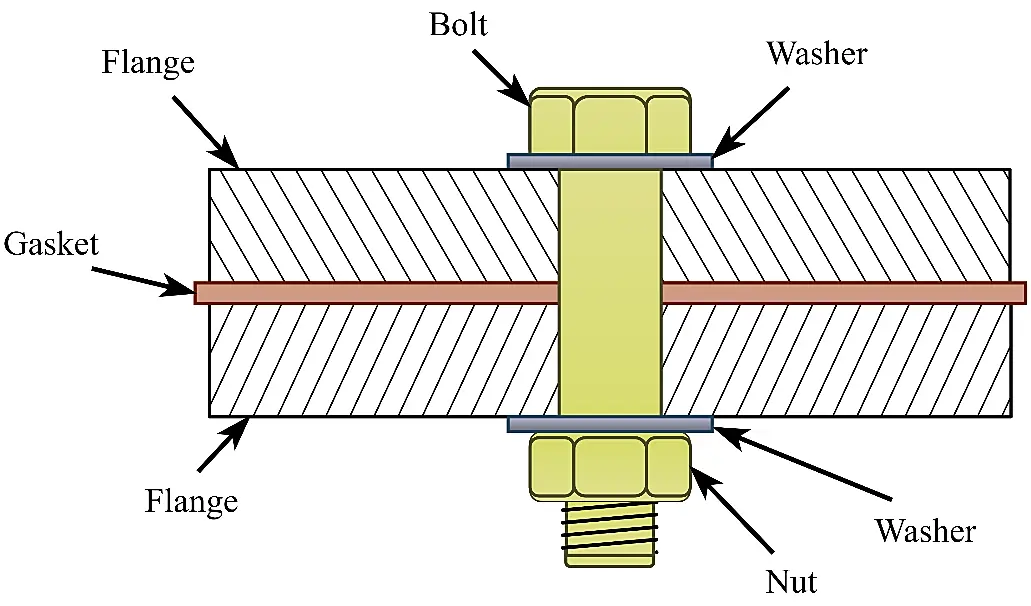
Bolted connections are used in countless practical applications, and bolt sizes can range from as small as M2 up to as large as M100. Figure 1 shows a simple diagram of a bolted flange, where the two sides of the flange are separated by a shim, or gasket, and held in place by the tensioned bolt and nut. Washers are used to increase the grip of the bolt and nut on the flange plates. Gaskets increase the ability to maintain the watertightness of the connection.
A certain amount of preload is required to maintain the structural integrity of the flange and the assembled structure. By tightening the nut, the bolt shank will be stretched, resulting in a tensile force in the bolt. As a result, the nut and bolt head will add compressive tension on the flange plates, which results in the clamping force holding the flange plates in place. Typically, two methods are used for tightening the bolts; the most common method is by torquing the nut directly with hydraulic or pneumatic torque wrenches.
A less common approach is by applying tension on the shank—and therefore stretching it by a certain measure—then lightly tightening the nut and finally releasing tension on the bolt shank. Correctly applied preload is crucial; too little preload could cause bolt loosening, and too much preload could cause the bolt to break, both conditions could lead to failure of the connection [8].
A recommendation for the amount of preload when applying torque is as follows [9]:
|
```latex{F}_{P}=0.7{f}_{Y}{A}_{s}``` |
(1) |
where FP is the applied torque load, fY is the yield resistance of the bolt material, and As is the tensile stress area of the bolt.
A recommendation for the amount of preload with tension-controlled methods is as follows [9]:
|
```latex{F}_{T}\le 0.95{f}_{Y}{A}_{s}``` |
(2) |
where FT is the applied tension load, and again fY is the yield resistance of the bolt material, and As the tensile stress area of the bolt.
The most prevalent bolt size used in offshore wind applications is M72 [10,11]. Braithwaite and Mehmanparast investigated the effects of the tightening sequence of bolts on preload [11]. They found that M72 bolts used to connect monopiles and transition pieces of bottom-fixed Offshore Wind Turbines (OWT) are sensitive to preload loss due to several factors, such as frictional effect, thread engagement, misalignment, plastic deformation, and temperature creep. It is difficult to achieve a uniform preload in all bolts, particularly in connections with many bolts, such as ring flanges on OWTs, due to elastic interaction between bolts. Hence, the well-known practice of altering the pattern of tightening sequence. However, Braithwaite and Mehmanparast found that altering the tightening pattern of ring flanges with M72 bolts has a negligible effect on combating preload loss. Instead, they found that a second round of tightening is effective in achieving and maintaining the desired preload. Karlsen and Lemu [12] investigated the effectiveness of locking mechanisms to maintain tension in preloaded bolts. Their tests showed that the bolts with the locking mechanism experienced minimum preload loss, compared to standard bolts, which did show significant preload loss. However, the biggest size bolts they tested were M42, no tests with M72 bolts were performed.
4. Flange Types
Standard ring flanges, also referred to as L-type flanges, are currently the technology of choice to connect WTG tower sections [13], and to connect the WTG tower with the foundation of OWTs [14], both for bottom-fixed OWTs as well as FOWTs.
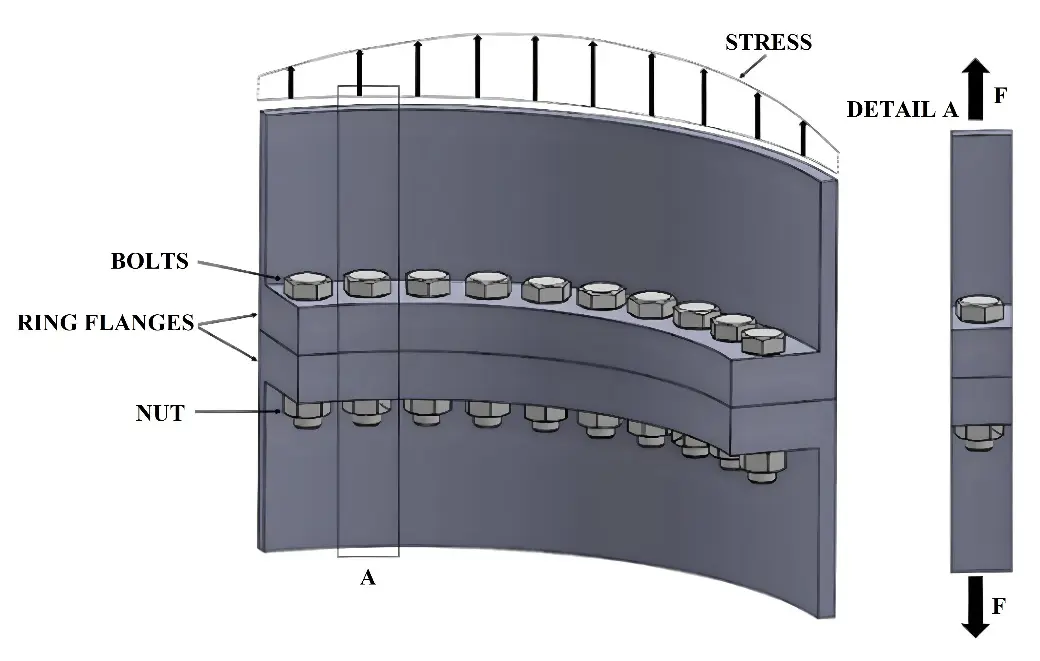
Typically, ring flanges for offshore wind applications will use a significant number of large diameter bolts (up to 100 per flange) equally spaced, as shown in Figure 2. The ring flange is designed to withstand Ultimate Limit State (ULS) and Fatigue Limit State (FLS) associated with local conditions. Some of the challenges with ring flanges include the choice of material, loosening of bolts, issues with load distribution in bolt threads, and static failure of the flange [6]. Ji et al. [15] used the Finite Element Method (FEM) to investigate the effects of any imperfections in the flatness of the flange plates (i.e., gaps between the flange plates) might have on flange performance. They found that tensile stress on the flange increases significantly with imperfection of the flatness on the flange side compared to perfect flatness. For imperfections in the flatness on the tower side, they found that compressive tension increases compared to perfect flatness. Both effects also resulted in an increase in fatigue damage of the bolts. Liu et al. [16] and Zou et al. [17] also investigated the effects of imperfections, or gaps, in flanges on the fatigue life of the bolts and connections and came to similar conclusions as Ji et al. Madsen et al. [18] also investigated L-flanges numerically and compared ULS and FLS results to experimental results. They found that imperfections and fabrication tolerances must be accounted for in numerical models to avoid underprediction of ULS and FLS.
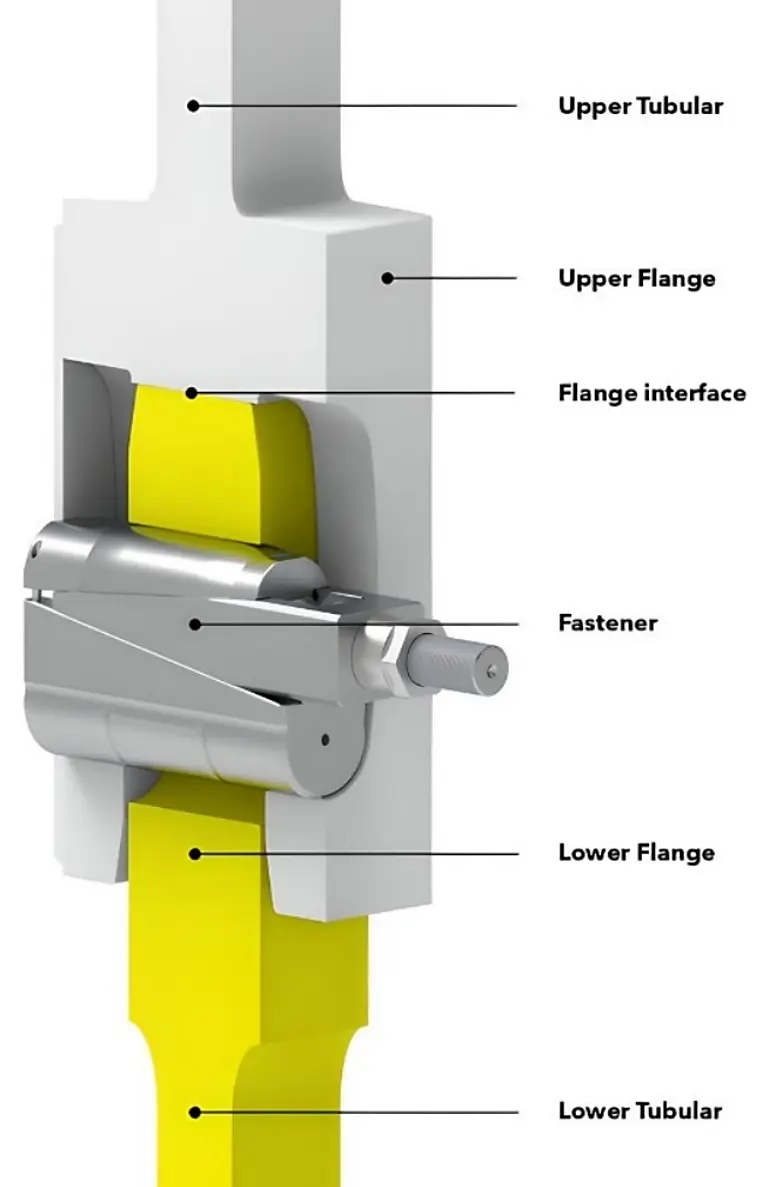
As WTG sizes, and therefore flange and bolt sizes, continue to grow, it becomes increasingly challenging to design L-flanges for OWTs. To address these challenges, the C1 Wedge Connection was developed [19,20]. As shown in Figure 3, a fork-shaped flange welded to the upper tubular slides over the lower tubular. Both the lower tubular and forked flange have corresponding radial elongated holes at equal spacing, allowing wedge fasteners to pull the tubulars together. The wedge fasteners consist of a horizontal bolt with a wedge shape at the end of the shank (faded blue lines in Figure 3), which is tightened with a nut, and which slides in a U-shaped wedge with its cheeks oriented opposite (clear blue lines in Figure 3) to the wedge on the bolt. A further two wedge blocks, above and below the sliding wedge, are pushed out when the nut is tightened. The assembly slides in the elongated holes in the tubulars, which are locked together when the nut is tightened, and the wedge blocks push against the inner edges of the holes. Creusen et al. [20] claim the C1 Wedge Connection is less susceptible to preload loss than conventional L-flanges and bolts, as “the orientation of the bolt in the fastener prevents significant load fluctuations under external loading”. As a result, maintenance and inspection requirements could be reduced when using the C1 Wedge Connection.
The developers of the C1 Wedge Connection also point out that the connection is symmetrical, unlike the L-flange, which makes them less susceptible to gaps in the flange. Potentially, this results in improved water tightness retention of the C1 Wedge Connection compared to L-flanges.
Cheng et al. [21] investigated the tensile behaviour of the C1 Wedge Connection both experimentally and numerically. They found that a small amount of preload on the horizontal wedge bolt results in a large vertical preload in the wedge connector. They also found that stiffness degradation in the wedge connector only occurs when the imposed load exceeds the critical load, and that the loss of bolt pre-tension does not influence the ultimate tensile load resistance. Furthermore, they found that the FEM analysis matched closely with the experimental results. Cheng et al. [22] performed a quantitative comparison between conventional bolted ring flanges and the C1 Wedge Connection using FEM. They found that the degradation of fatigue resistance of bolted ring flanges is seven times higher compared to the C1 Wedge Connection in their simulations.
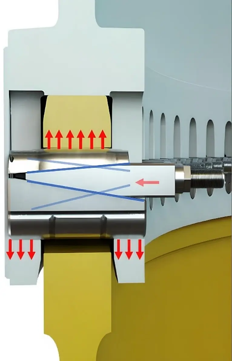
Another alternative to the conventional ring flange is the Compact Flange Connection (CFC) [23]. The CFC is mainly used to connect riser pipe components in the O&G industry and has proven reliable, requiring no maintenance after several decades of operation. By warping the flange plate faces and deliberately creating a small gap on the flange side, the bolts are tightened under high tension at the assembly stage to pull the flange plates together. This is shown in Figure 4. The high preload closes the flange plates, which essentially act as stiff springs, preventing loosening of the nuts. As a result, most of the preload is transferred as compressive force to the heel at the tubular end of the flange. This creates a “static” connection, meaning that bolt tension does not vary under applied loads on the connection, and applied seating stress remains higher than design loads. If dynamic loads do not exceed the material capacity of the connection, this results in a maintenance-free, reliable connection.
Lutkiewicz et al. [24] compared CFCs to conventional flanges and found high reliability, static behaviour, low weight, and compact dimensions for the CFC compared to conventional flanges for similar operational conditions. However, due to patents on the CFC, its use is not widespread outside the European region, where it is most commonly used in Norway’s offshore industry [23].
Table 1 shows an overview and comparison of conventional L-flanges, CFC, and C1 Wedge Connection when intended to be used for the assembly of FOWT foundations.
Table 1. Overview and comparison of different connection types.
|
Connection Type |
Performance |
Maturity Level |
Complexity |
Patent? |
|---|---|---|---|---|
|
Conventional L-flanges |
Prone to bolt loosening and ‘gapping’. Reduction of fatigue life and loss of watertightness if loosening and gapping occur. Unclear what performance will be when mounted vertically in FOWT foundations. |
Extensively used for tower connections in offshore wind |
Large flange plates and bolts, but with a simple structure, easy to mass-produce |
No |
|
Compact Flange Connection |
Excellent at maintaining preload and watertightness. Proven to withstand high dynamic loads in offshore conditions. Likely to perform well in FOWT foundations, but more research and demonstration are required for confirmation. |
Excellent track record in offshore O&G, but has not applied in offshore wind yet. |
Moderate to large flange plates and bolts. The warped faces of the flange plate add some complexity. Relatively simple structure. |
Yes |
|
C1 Wedge Connection |
Tests so far show good preload and watertightness retention. Likely to perform well in FOWT foundations, but more research and demonstration are required for confirmation. |
Still in the development phase, tested as a tower flange for a 14 MW turbine. |
Relatively small flanges and bolts, but additional mass from wedges. More complex structure compared to conventional flanges and CFC. |
Yes, and some pending |

Figure 4. Compact Flange Connection. 1: Wedge, 2: Stud, 3: Nut, 4: Seal ring, 5: Heel, 6: Weld neck flange, 7: Bolt clamping force. The arrows indicate the tension of the nuts applied on the flange, and the compressive forces on the flange plates and seal ring.
5. Bolt Loosening
One of the main concerns of using bolted connections to assemble the components of FOWT foundations is the risk of bolt loosening during the operational stage. Bolt loosening in the connections of the foundations would result in increased fatigue in the bolts and consequently would require increased maintenance and shorter inspection intervals of the FOWTs. This will increase Operational Expenditure (OPEX) with potential negative effects on Levelized Cost of Energy (LCOE), which could negate any cost savings made during the assembly/installation stage. Furthermore, bolt loosening is found to increase the risk of bolt failure [7,11,25], which consequently could result in catastrophic failure of the FOWT.
Loosening occurs when the friction resistance between the threaded surfaces of the bolt and nut is overcome. The most common contributors to bolt loosening are preload loss and vibrations in the connection [11,25]. In OWTs, vibrations are caused by structural loadings of the operational WTG, and environmental loadings, mainly from wind, waves, and current. In FOWTs, vibrations are compounded by inertia loads due to the dynamics of the structure in the six DOFs. Various methods to prevent bolt loosening can be employed [6], such as maintaining friction forces of the connection above external loading, e.g., [23], or using counter torque or locking mechanisms, e.g., [11].
Due to the risk of bolt loosening frequent inspections to measure preload are required, as it is difficult to visually determine loss of preload [12]. The simplest method to measure looseness is by applying the required torque to the nuts with appropriate tools. Javadi et al. [26] propose a method combining robotics, ultrasonic testing, nonlinear acoustoelasticity, and FEM analysis to measure preload. Results of their study show high accuracy of measurements; however, the authors acknowledge their method is complex with high requirements of hardware, software, and skills.
He and She [27] propose a different method by measuring the vibrations in the flange plates of bolted connections. They found that the phase difference between the upper and lower plate suddenly increases when loose bolts are present in the connection, and suggest their result can provide a new method to identify bolt looseness.
Typically, bolt preload on OWTs is checked annually by re-tightening 10% of the bolts [11]. Vanden Haute and Pire [28] investigated the requirements for inspection and maintenance intervals of bolted connections using inspection results from an existing bottom-fixed offshore wind farm, which uses tension-controlled bolts [29] for the ring flanges. They found that the use of tension-controlled bolts resulted in 3–5% of bolts needing re-tightening, and that the amount of bolt loosening reduced after re-tightening. In their case study, they found that a permanently acceptable state was reached after the first 4 years of operation with relatively short intervals. After the first 4 years, Vanden Haute and Pire suggest the maintenance and inspection intervals could be lengthened at the discretion of the wind farm operator. However, typically maintenance intervals will shorten, rather than lengthen, as the age of wind farms progresses.
Valdez et al. [30] experimentally developed a method to monitor bolt looseness using a laboratory scale model of a jacket structure OWT. Their method involves continuous monitoring of vibrations in the structure, a form of structural health monitoring. It uses principal component analysis and Mahalanobis distance calculation to detect loose bolts. They simulated wind loads by introducing vibrations at the nacelle height of the model and measured the resulting structural vibrations with several accelerometers placed around the scale model. They only simulated wind loads during their experiments, but no wave- or current loads. Damage of the structure was simulated by varying the preload of some bolts in the structure and comparing the results against the vibrations of the undamaged model. They found their method resulted in good detection of loose bolts with minimal false alarm detections.
6. Corrosion
As FOWTs will be operating in a harsh marine environment, corrosion is another risk to which bolted connections will be exposed. Dynamic loadings combined with exposure to seawater result in an elevated risk of corrosion and associated acceleration of fatigue damage of OWT structures [31]. Corrosion will also affect the fatigue performance of bolts and can also lead to preload loss [6,25,31,32]. Coatings can be applied to bolts to resist corrosion, such as zinc treatments, and other types of coatings [6]. However, Schaumann [33] showed that galvanisation reduces the fatigue life of bolts. Of course, corrosion would have a greater negative impact on the fatigue life of bolts, therefore, Schaumann argues that a somewhat conservative fatigue life design for bolted connections can account for the effect of galvanisation. Another potential solution to mitigate corrosion is to choose a corrosion-resistant material for the bolts, such as stainless steel or titanium [25]. However, these would require insulation to prevent galvanic corrosion and come at a higher cost compared to conventional steel. Typically, only conventional steel bolts are used in offshore wind applications [6].
Zhang et al. [34] investigated the effects of corrosion fatigue deterioration of bolts and ring flanges in FOWT structures. They combined site specific data, aero-hydro-elastic simulations in OpenFast, load transfer functions based on the Schmidt-Neuper approach, specific material properties, and Monte Carlo simulations to model probabilistic corrosion fatigue evolution. They found a strong correlation between wind- and wave direction, and wind velocity on the one hand, and corrosion fatigue damage on the other hand. Their models showed that the fatigue life of equivalent tower bolts reduced from 67 years for onshore conditions to 20 years for the modelled FOWT at a specific site in the Gulf of Mexico.
7. Fatigue
Over their lifetime, FOWT structures will accumulate fatigue from variable cyclic loadings. These are the result of wind, waves, and current excitation of the FOWT structure, and inertia loads of the moving structure resulting from said environmental loads. As floating wind energy is still in its infancy, the realisation that novel methods are required to predict long-term fatigue damage of FOWT structures is starting to trickle into the literature, e.g., [35]. Typically, fatigue life of offshore wind structures is calculated based on the S-N approach, assuming linear cumulative damage based on fatigue calculation theories such as Palmgren-Miner [36]. The accumulation of fatigue damage is defined by DNV as [37]:
|
```latexD={\sum }_{i=1}^{k}\frac{{n}_{i}}{{N}_{i}}=\frac{1}{a}{\sum }_{i=1}^{k}{n}_{i}{\left({∆\sigma }_{i}\right)}^{m}\le \eta =\frac{1}{DFF}``` |
(3) |
where D is the accumulated fatigue damage, a is the intercept of the design S-N curve with the log N axis, m is the negative inverse slope of the S-N curve, k is the number of stress blocks, ni is the number of cycles in stress block i, Ni is the number of cycles to failure at constant stress range ∆σi, η is the usage factor, and DFF is the design fatigue factor.
So far, bolted connections have only been proposed for steel semisubmersible FOWT foundations. The connections between braces and floatation columns are the main load bearing components and crucial parts in the structure. If these connections are made with bolted flanges, fatigue life analysis of the bolts will form a crucial part of the design of the structure. Forces acting on preloaded bolts in ring flanges for tower connections are predominantly axial stresses, therefore, S-N curves for the design of large diameter bolts used in OWTs are based on fatigue tests under pure axial loading [33].
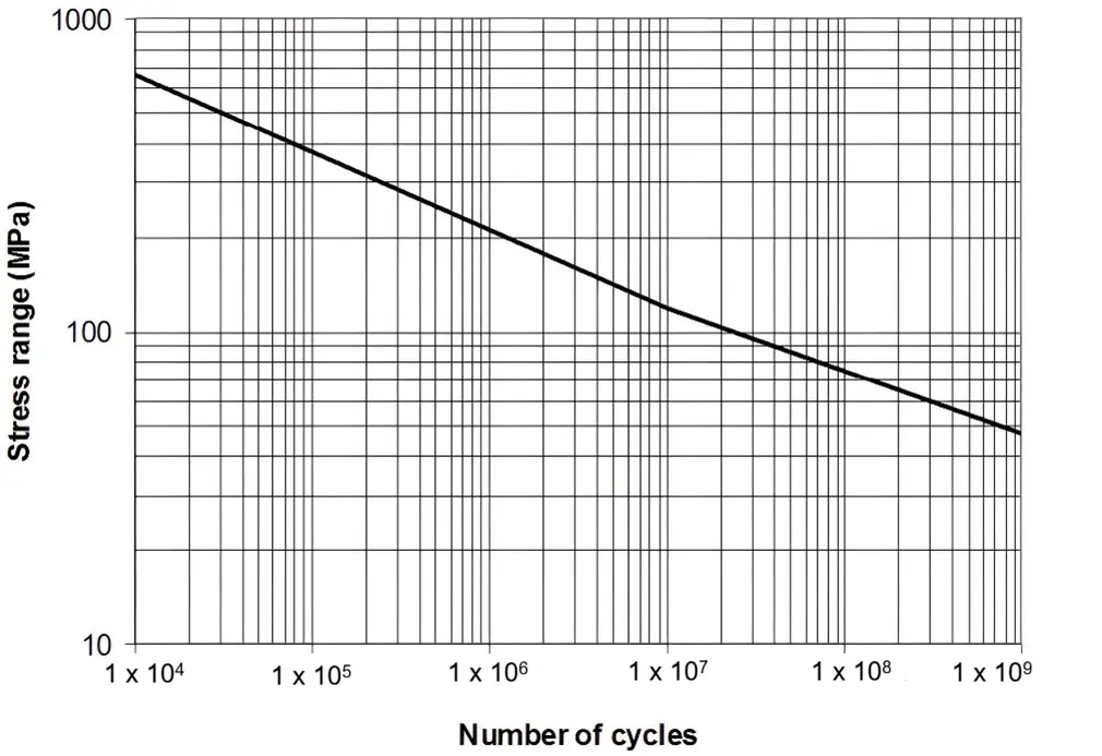
A basic design S-N curve defined by DNV is as follows [37]:
|
```latex\mathrm{log}N=\mathrm{log}a-m\, \mathrm{l}\mathrm{o}\mathrm{g}\,∆\mathrm{\sigma }``` |
(4) |
where N is the predicted number of cycles to failure for stress range ∆σ, however, typically, large diameter M72 bolts are used in offshore wind applications. International design codes provide S-N curves for such large diameter bolts, however, the reference diameter in these codes is for bolts of 25 mm or 30 mm diameter. A thickness correction is provided to account for larger diameter bolts. The corrected S-N curve then is defined as [37]:
|
```latex\mathrm{log}N=\mathrm{l}\mathrm{o}\mathrm{g}\mathrm{ }a\mathrm{ }-\mathrm{ }m\,\mathrm{ }\mathrm{l}\mathrm{o}\mathrm{g}\left(\mathrm{\Delta }\sigma {\left(\frac{t}{{t}_{ref}}\right)}^{k}\right)``` |
(5) |
where tref is the reference thickness, which is assumed to be 25 mm by DNV, and t is the thickness through which a crack will most likely grow, and where t = tref when the thickness is less than the reference thickness. Figure 5 shows a typical S-N curve as an example.
In some cases, when bolted connections are used in FOWT foundations, the connection will be mounted vertically when the foundation is in its equilibrium position in still water. For example, when the braces and floatation columns of steel semisubmersibles are assembled. Consequently, shear forces will be the dominant forces acting on the bolts. As a result, demands on such bolts will be more stringent, and S-N curves need to be adapted. For bolts subjected to shear forces, DNV defines the S-N curve as [37]:
|
```latex\mathrm{log}N=16.301-5.0\mathrm{log}\mathrm{\Delta }\sigma``` |
(6) |
where ∆σ is the stress range on the shank area of the bolt. However, this review has shown that no research has been conducted to date to validate its suitability for large diameter bolts used in connections to assemble FOWT foundations.
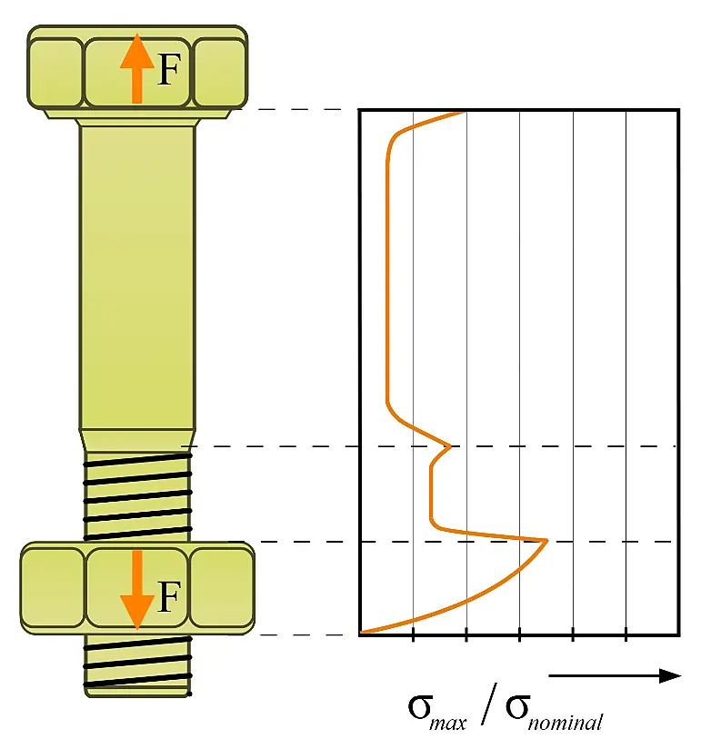
The evolution of fatigue failure in bolts begins with crack initiation, followed by crack propagation, and finally complete rupture [6]. Failure of one bolt in a ring flange will lead to reduced clamping force and increased stress on neighbouring bolts, which could eventually lead to a chain reaction and complete failure of the connection. Initial cracks can start under fatigue loading at spots of material flaws, or at points of high stress [7,14]. Figure 6 shows the three main areas of stress concentration in bolts and nuts. Typically, fatigue failures will occur in one of these areas [7,38].
Fatigue design remains a key challenge, especially since offshore wind turbines and their support structures continue to grow in size [39]. Although the body of literature on fatigue-related research for FOWTs is limited, significant research has been conducted on onshore wind turbines and bottom-fixed OWTs, which could be transferable to FOWTs.
Liu et al. [40] investigated fatigue performance and reliability of bolts used in wind turbine tower flanges, combining FEM and theoretical fatigue models. They argue that bolt failures are difficult to detect early, and therefore, predictive analysis is essential.
Gao et al. [41] propose a Machine Learning (ML) based approach to fatigue analysis of tower flange bolts to improve prediction accuracy and computational efficiency. They used GH Bladed to simulate and calculate the wind loads and used the Schmidt-Neuper algorithm to determine the fatigue loads on the bolts. They then converted the fatigue data into an Equivalent Fatigue Stress (EFS) and experimented with various ML-based algorithms for the mapping of fatigue damage under various wind conditions. They found that the XGBoost algorithm provided the highest accuracy results of fatigue damage compared with their original model.
Kikuchi and Ishihara [42] investigated an accident at an onshore wind farm where the failure of 14 out of 60 high-tension bolts and a tower shell caused the nacelle to crash to the ground. By using aero-elastic modelling and FEM analysis, they attempted to predict bolt- and tower fatigue life. Those models were validated by on-site measurements and maintenance records. They found that fatigue life of the bolts dropped from 21 years for intact bolts with 80% residual axial tension to 0.25 years for damaged bolts with less than 30% residual axial tension. This was confirmed by the maintenance records of the wind turbine, which showed that bolt failure occurred 3 months after the last inspection. An investigation after the incident showed that the failure of the bolts accelerated the damage to the tower shell and, therefore, the failure of the wind turbine. The investigation also showed that maintenance and re-tensioning of the bolts were not conducted adequately. These findings confirm the requirement for rigorous inspections and maintenance if bolted connections are going to be used for the assembly of FOWT foundations.
Johnston and Dore [43] investigated whether the thickness correction factors proposed in the international standards are appropriate. They conducted tests with galvanised M72 bolts and with uncoated M64 and M72 bolts for comparison. They found that the correction factor for uncoated M72 bolts in the standards is appropriate, however, the results of their tests with galvanised M72 bolts were slightly below the existing recommendations.
Eichstädt [44] conducted experiments on M36 and M64 bolts and compared the effects on fatigue life of hot-dip galvanised bolts and uncoated bolts. The tests were conducted with axial loading at high mean stress, and both static and dynamic loads were applied. He found that the reduction of fatigue life due to the hot-dip galvanising was confirmed, and found as much as a 20% reduction. However, he also found a significant reduction in fatigue life with the uncoated M64 bolts compared to the uncoated M36 bolts. On the other hand, he did not find a significant difference in fatigue life between the coated and uncoated M64 bolts, putting into question the superior fatigue life of large diameter black uncoated bolts, commonly in use OWTs.
Annoni et al. [14] compared existing fatigue data points of large diameter bolts with design curves recommended in international standards to investigate the accuracy of thickness correction factors and compared these results with fatigue experiments they conducted on M72 bolts. They found that collated data points and data points from their own tests all fell above design S-N curves found in international standards, meaning the standards take a somewhat conservative approach. However, they also found that the inverse slope of their data point collection could dip below the S-N curves of the standards at lower stress levels. They argue that more test results are needed to confirm these results.
Rincón-Casado et al. [45] developed an experimental methodology to estimate the residual fatigue life of in-service bolts. They used M16 bolts with controlled pre-damage to simulate operational damage for their fatigue tests. They found that displacement of the nut from its intended position resulted in deviations of fatigue estimations. Additionally, they developed a method to estimate the fatigue life of new bolts by testing used M20 bolts from a damaged wind turbine. By displacing the nut relative to its original position, they avoided applying high levels of stress on the damaged region of the bolt. They argue that, although their tests were performed with small diameter bolts, they can be transferable to tests with larger diameter bolts.
Croccolo et al. [25] describe phenomena, besides the well-known ones such as vibrations and corrosion, which attribute to bolt and flange fatigue, including fretting. Fretting occurs when frictional contacts are allowed to move, which forms microcracks, which can turn into bigger cracks at stress hot spots. They also conclude that a significant portion of fatigue failures in bolts and flanges are the result of incorrect assembly.
8. International Standards Covering Bolted Connections for FOWTs
International standards and guidelines that cover bolted connections in offshore wind structures typically focus on aspects such as fatigue performance, corrosion resistance, preload requirements, and structural integrity. However, their coverage of FOWTs is inconsistent and often based on fixed-bottom practices. An overview of the most relevant standards and their scope is provided in Table 2.
ISO 898-1 [46] establishes mechanical property requirements and strength classes for carbon and alloy steel fasteners, forming the basis for bolt selection. Additional ISO standards relevant to offshore wind include ISO 12944 [47] for corrosion protection of steel structures, ISO 12473 [48] for cathodic protection principles in seawater, ISO 2768 and ISO 4759 for tolerances and dimensional requirements, ISO 16047 [49] for determining the torque–tension relationship, and ISO 19902 [50] for structural integrity and fatigue guidance in fixed offshore structures. However, these standards generally do not provide detailed prescriptions for bolted joint fatigue or preload in floating applications.
VDI 2230 [51] provides analytical methods for calculating highly stressed bolted joints, focusing on preload determination, tightening procedures, and fatigue safety under dynamic loads. BS 7608 [52] offers fatigue assessment rules for steel joints, including bolted connections, using S–N curves, but does not cover preload or corrosion. Eurocode 3 [53] specifies fatigue verification for bolted joints and slip-resistant connections. Corrosion protection, however, is addressed by complementary standards such as ISO 12944 [47] for coatings and EN 1090 [54] for execution requirements, rather than within Eurocode 3 itself. ASME PCC-1 [55] focuses on bolted flange assembly and tightening practices, providing guidance on preload and inspection, but with only limited coverage of fatigue and corrosion. IEC 61400-3-2 [56] defines design requirements for floating offshore wind turbines, including load cases, fatigue assessment, and robustness checks, though it lacks detailed bolt-specific prescriptions.
Among standards and guidelines produced by offshore and marine classification and certification bodies, DNV-ST-0126 [9] outlines design principles for support structures, including ULS and FLS checks for bolted joints and slip-resistant connections. DNV-ST-0119 [57] addresses floating wind applications with guidance on bolted joint integrity, preload, and inspection, while DNV-RP-C203 [37] provides fatigue design methodologies using S–N curves and fracture mechanics. The ABS Guide for FOWTs [58] addresses structural integrity requirements for bolted joints within FOWT foundations, referencing IEC 61400-3-2 [56] for turbine design considerations. It incorporates fatigue life evaluation and strength checks for bolted connections to ensure reliability under dynamic offshore conditions.
Lloyd’s Register (LR) provides recommended practice for fixed and floating offshore wind structures [59,60]. It aligns with IEC 61400-3-2 [56] and ISO standards, emphasizing fatigue verification, corrosion protection, and inspection throughout the project lifecycle. While LR does not include detailed bolt design formulas, it requires compliance with international fatigue and corrosion standards and adopts risk-based inspection strategies for bolted joints under dynamic loads. For fixed-bottom structures, LR references Eurocode [53] and IEC [56] for fatigue and preload checks, supplemented by corrosion protection measures.
Bureau Veritas (BV) [61,62] addresses bolted joint integrity for FOWT foundations. BV requires fatigue and corrosion checks using S–N curves and ISO coating standards, while preload and inspection are embedded in its risk-based lifecycle approach. For fixed-bottom structures, BV applies similar principles, delegating detailed bolt design to referenced standards such as Eurocode [53] and VDI 2230 [51].
Table 2. Technical Coverage of Bolted Connections in Offshore Wind Standards.
| Standard/Guideline | Design Approach for Bolted Joints | Fatigue | Corrosion | Preload Requirements | Inspection & Maintenance | FOWT Bolting Guidance |
|---|---|---|---|---|---|---|
| ISO (898-1, 12944, 12473, 16047, 2768, 4759, 19902) | Material properties, corrosion protection, tolerances, and structural integrity | ✔ | ✔ | ✔ | ~ Limited | ✗ |
| VDI 2230 | Analytical calculation for high duty bolted joints under static/dynamic loads | ✔ | ✗ | ✔ | ✗ | ✗ |
| BS 7608 | Fatigue design using S–N curves for steel joints, includes bolts | ✔ | ✗ | ✗ | ✗ | ✗ |
| Eurocode 3 (EN 1993-1-9) | Fatigue verification for bolted joints and slip-resistant connections | ✔ | ~ Limited | ✔ | ✗ | ✗ |
| ASME PCC-1-2010 | Bolt assembly and tightening for flange joints | ~ Limited | ~ Limited | ✔ | ✔ | ✗ |
| IEC 61400-3-2 | Offshore wind turbine design; includes fatigue checks DLCs | ✔ | ✔ | ~ Limited | ✔ | ✔ |
| DNV-ST-0126 | Offshore wind support structures; includes slip-resistant bolted joints | ✔ | ✔ | ✔ | ~ Limited | ~ Limited |
| DNV-ST-0119 | Floating wind turbine design; bolted joint integrity and inspection | ✔ | ✔ | ✔ | ✔ | ✔ |
| DNV-RP-C203 | Fatigue design for bolted joints using S–N curves and fracture mechanics | ✔ | ✗ | ✗ | ✗ | ~ Limited |
| ABS Guide for FOWT | Classification rules; fatigue and preload checks for bolted joints | ✔ | ✔ | ✔ | ✔ | ✔ |
| Lloyd’s Register (LR) | Lifecycle guidance; references IEC/ISO for bolted joints | ~ Limited | ✔ | ~ Limited | ✔ | ✔ |
| Bureau Veritas (BV) | Certification framework; generic bolted joint requirements | ~ Limited | ✔ | ~ Limited | ✔ | ✔ |
Note: ✔ Covered in detail; ✗ Not covered; ~ Limited coverage or generic guidance.
9. Comparison of Bolted and Welded Connections
The welded construction of offshore wind platforms, including FOWT foundations, relies on high-efficiency welding techniques suited for large-scale structural construction. Common arc welding processes utilised in offshore structures fabrication include: (a) Gas Metal Arc Welding (GMAW), (b) Shielded Metal Arc Welding (SMAW), (c) Flux-Cored Arc Welding (FCAW), (d) Gas Tungsten Arc Welding (GTAW), (e) Submerged Arc Welding (SAW) [63]. These welding technologies are shown in Figure 7.
GMAW, often referred to as metal inert gas (MIG) welding, is a rapid and relatively simple joining process. Its capability to produce high-quality, robust welds has made it one of the predominant methods in large scale manufacturing [64,65]. The GMAW process employs an electric arc between a continuously fed consumable wire electrode and the workpiece, while a shielding gas protects the weld from atmospheric contamination. Variants include Metal Inert Gas (MIG) welding, which uses inert gas shielding, and Metal Active Gas (MAG) welding, which uses an active gas shielding [66]. GMAW offers high deposition rates, versatility for a wide range of materials and thicknesses, and adaptability to mechanised systems. However, GMAW is not ideal for outdoor welding work due to wind-sensitive shielding gas.
GMAW has been qualified for use in hyperbaric conditions, supporting operations such as fillet sleeve repairs and remote hot tapping. The process demonstrates the capability to weld at depths approaching 1000 m [67].
SMAW is a manual welding process, also known as stick welding, that uses a consumable, flux-coated electrode to create an electric arc between the electrode and the metal workpiece, producing heat that melts both to form a weld [67,68]. Fabricators typically apply SMAW to TKY-joints [69] because it supported by established procedure qualifications, benefits from the wide availability of certified welders, and it is well-suited for outdoor environments [70]. SMAW remains the preferred method for on-site repairs and maintenance, particularly in harsh marine environments where portability and versatility are essential. However, SMAW has drawbacks such as slower deposition rates, higher labour intensity, and susceptibility to defects like porosity and hydrogen-induced cracking in wet welding conditions, which can compromise weld quality [71].
Another weld technique is the FCAW which is suitable for thick-walled components. FCAW is a welding process that employs a continuously fed tubular wire electrode containing flux, which, together with an electric arc, melts the base metal to form the joint. The flux provides shielding and often produces a protective slag over the weld surface [72]. FCAW provides excellent performance under outdoor conditions. This is because it uses flux within the wire, which provides shielding and makes it less sensitive to wind and contaminants compared to processes like GMAW [70,73]. In addition, FCAW can be applied in all welding positions, flat, horizontal, vertical, and overhead, offering flexibility for diverse project requirements, such as rack-to-chord, column-to-brace, and brace-to brace joint connections in offshore jackets [67]. A major drawback of FCAW is the substantial emission of smoke and fumes during operation, which necessitates effective ventilation and strict safety precautions to safeguard the welder [72].

Precision welding of corrosion-resistant alloys and critical joints often utilizes GTAW, also called Tungsten Inert Gas (TIG) welding [79]. This welding method uses a non-consumable tungsten electrode to create an arc that melts the base metal, while an inert gas such as argon or helium shields the weld from contamination. It produces precise, high-quality welds on thin sections and non-ferrous metals, and filler material can be added separately when needed. Although is method is generally slower and more labour-intensive compared to GMAW [80].
The fifth technique is the SAW, a fusion process in which a continuously fed wire electrode forms an arc with the workpiece beneath a granular flux layer. The flux provides shielding, reduces spatter and fumes, and produces clean, high-quality welds. SAW is widely employed for fabrication of heavy tubular joints and offshore monopiles due to its strong deposition rates, and deep weld penetration, which are essential for joining thick steel plates used in these large-diameter structures [81]. Moreover, the SAW weld process can be used in automated setups, resulting in enabling consistent weld quality and productivity for circumferential and longitudinal seams. A key limitation of SAW is its inability to handle vertical or overhead positions, as the granular flux cannot remain in place on non-horizontal surfaces [82].
For floating offshore wind platforms, the choice between welded and bolted connections significantly influences fabrication, installation, fatigue behaviour, and maintenance strategies. Welded joints, provide high structural continuity and strength, which is advantageous for large scale tubular sections. However, these methods require specialised equipment, controlled conditions, and extensive labour. A comparison between Metal arc welding technologies and bolting connections in different aspects is provided in Table 3.
As shown in Table 3, an important characteristic of welded joints is the deposition rate, which is defined as the mass of weld metal melted into the joint per unit of time (kg/h). Although deposition rate varies with parameters such as electrode type and diameter, welding current and voltage, degree of automation, and joint configuration, typical values reported in [83,84,85] for large-scale structural assemblies are presented in Table 3 for general comparison. Deposition rates vary significantly across arc welding methods, ranging from 0.4–16 kg/h. Installation time follows a similar trend: GTAW is very slow due to precision requirements; SMAW is slow due to manual operation; GMAW and FCAW are moderate to fast owing to continuous wire feeding; SAW is fast for long welds despite setup requirements; and bolted connections are the fastest option for modular assembly.
Another critical factor is the maintenance requirements. Welded joints typically require little maintenance during service because they form permanent connections once properly executed and inspected [86,87]. However, fabrication demands rigorous quality assurance, including non-destructive testing, and offshore repairs are expensive and often involve specialised techniques such as hyperbaric welding [88]. Consequently, welding can be characterised as low maintenance in service but high in inspection complexity during fabrication. In contrast, bolted connections require periodic torque checks and occasional bolt replacement due to fatigue or corrosion [89,90,91]. They are generally easier to maintain since components can be replaced without cutting or rewelding, although such interventions can be challenging in offshore environments. Therefore, bolted connections can be described as easy to maintain but requiring frequent checks.
Table 3. Comparison of different welded methods versus bolted connections.
|
Method |
Deposition Rate (kg/h) |
Installation Time |
Maintenance |
Suitability (Application; Component/Thickness; Limitations) |
|---|---|---|---|---|
|
GMAW (MIG/MAG) |
3–12 |
Moderate to Fast (due to continuous wire feeding) |
Minimal |
Workshop fabrication, hyperbaric repairs; medium-thickness tubulars/braces; less ideal for open-air due to shielding gas sensitivity. |
|
SMAW (Stick) |
0.4–5.5 |
Slow (manual process, frequent electrode changes) |
Minimal |
On-site repairs; TKY joints, thin-to-medium tubular joints; slow and labour-intensive, prone to hydrogen cracking in wet conditions. |
|
FCAW |
1–15 |
Moderate to Fast (continuous wire feed, suitable outdoors) |
Minimal |
Outdoor structural welding; offshore jacket connections, medium-to-thick tubulars, all weld positions; high fume emission, requires slag removal. |
|
GTAW (TIG) |
0.5–2 |
Very Slow (precision-focused, meticulous control) |
Minimal |
Critical joints, corrosion-resistant alloys; thin sections, high-integrity welds; very slow, costly, requires high skill. |
|
SAW |
3–16 |
Fast for long welds (highly efficient for thick plates, but setup required) |
Minimal |
Automated welding of jacket legs and monopiles; thick plates, large tubulars; limited to flat/horizontal positions, high setup time. |
|
Bolted Connections |
n/a |
Very Fast (quicker than welding) |
Require periodic torque checks |
Fast modular assemblies; flange joints, pre-drilled plates; requires precise alignment, risk of loosening under vibration. |
10. Discussion
While the FOW industry recognises the potential benefits of bolted connections for the assembly of FOWT foundations, some concerns remain, particularly around bolt loosening and fatigue failure. As mentioned, if bolt loosening or failure becomes a regular occurrence on FOWTs, inspection intervals will increase, and regular maintenance to re-tighten or replace bolts will be required. Consequently, this will have a negative effect on the LCOE of affected wind farms.
As FOW is still a nascent industry, wind farm developers will be inclined to choose technology for their FOWT foundations that is proven to be reliable as far as possible. Perhaps it is therefore no surprise that most FOWTs with steel foundations, which are currently installed offshore have been welded at the assembly stage. Welding was pioneered in the 1930s and has since been widely applied in shipbuilding [92]. Steel floating structures in offshore O&G, such as semisubmersible drilling rigs, are also mostly welded. Automated welding limits material defects in welds and ensures a high-quality, reliable connection, with uniform distribution of stress throughout the weld [93]. In contrast, it is difficult to automate bolting, and issues with preload loss could lead to stress concentration in weak spots of the connection. Although the connection between the WTG tower and FOWT foundation is typically a bolted connection, the flanges are horizontally positioned, and the connection is mostly subjected to compressive forces, with mostly tensile forces in the bolts and some shear stress due to the motion of the FOWT. However, bolted connections between floatation columns and braces of the foundation will have the flanges positioned vertically. This means gravity, buoyancy, and motion of the FOWT foundation will significantly add shear stresses to the connection. These added stress concentrations result in higher fatigue in the bolted connections for the foundation compared to the tower connection. Such shear stresses and associated fatigue life in the foundation are likely easier to manage with welded connections compared to bolted connections.
Fatigue life is one of the driving factors in the design of FOWT foundations [94]. When FOWT foundations are assembled with bolted connections, there will be several additional welds in the structure, plus all the bolts, which will have to be designed for fatigue life. Therefore, potentially, bolted connections will add several extra stress points to the structure compared to a purely welded structure. Bolting does not eliminate the need for welding in the structure either; the flange plates will still need to be welded to the tubulars, although this is done at the fabrication stage and not at the assembly stage.
Any notches or imperfections in the weld connecting the flange plates with the tubulars will reduce the fatigue life of the connection. Local bending stresses will likely occur at the weld toes of bolted connections, potentially resulting in added fatigue damage. The fatigue resistance of these welds will need to be carefully modelled and accounted for in the design of FOWT foundations using bolted connections for assembly. In the case of the CFC- and C1 connections it is more likely that any failure due to fatigue will occur at the welds of the connection if any imperfections are present, rather than the bolts. It highlights again the need for thorough quality checks of all welds, as well as bolted connections, during the manufacturing and assembly of FOWT foundations.
So far, there are no examples in the literature of studies that investigated the effects of dynamic loads combined with shear forces on the fatigue life of vertically mounted bolted connections. Nor are there any examples in the literature investigating stress and fatigue in the transition between tubular and bolted connections in FOWT foundations.
Furthermore, bolted connections are heavier compared to welded connections; the weight of flange plates, bolts, and nuts exceeds the weight of welds for equivalent diameter connections. Due to its larger material content, the material costs of bolted connections will likely be larger compared to welded connections. However, this will likely be offset by gains from shorter assembly time.
Although some guidance for bolted connections in FOWTs is provided in the international standards (e.g., DNV-ST-0119 [57]), they do not include clear provisions for maintenance intervals or scope. Data about experience with large, bolted connections in FOWTs is limited.
Connections in FOWT foundations will likely be difficult to access and will generally be in confined spaces, therefore, maintenance on bolted connections in such locations may also form a potential Health and Safety risk. Particularly in large diameter tubulars (larger than 2 m) for braces in full-scale FOWT foundations, the bolts in the top part of flanges may be difficult to reach. This problem may be exacerbated when heavy tools are required for the re-tightening of bolts inside a dynamic structure. Therefore, some form of scaffolding may need to be erected, or other measures may be required, assuming the bolts are on the inside of the tubular.
Maintenance in offshore wind is typically WTG driven [95,96], so FOW developers will generally want to limit maintenance interventions to the WTG and avoid maintenance for the foundation as much as possible. Hence, welding is often preferred for the assembly of FOWT foundations due to its reliability. Several designers of FOWT foundations have also expressed higher confidence in welding to maintain the structural integrity of their structures and eliminate maintenance as much as possible. Welding for connections in offshore structures is well tested and proven reliable and would therefore accommodate low maintenance and long inspection intervals for FOWT foundations. Of course, welds will still need to be inspected; however, generally inspection intervals can be up to 5 years depending on standards, marine warranty, etc. Conventional ring flanges, or L-flanges, are unlikely to be suitable for the assembly of FOWT foundations due to the following:
-
-
The literature shows that ring flanges are subject to bolt loosening and require re-tightening, although after re-tightening, preload loss seems to be limited.
-
-
Bolt loosening significantly reduces the fatigue life of the connection.
-
-
Bolt loosening may affect water tightness of the connection and could result in water ingress.
-
-
Re-tightening loose bolts will have to take place in confined spaces, which may be difficult to access.
-
-
Flange plates will need to be perfectly flat to avoid added stress in the connection due to fabrication defects.
The C1 Wedge Connection is potentially a technology with limited preload loss and could be suitable for a low-maintenance application. However, the technology is currently still in the development phase and has not been applied in FOWT foundations yet. Furthermore, tests with the C1 Wedge Connection so far have all been for tower connections, meaning the connections have all been mounted horizontally. No tests have been performed yet where the connection is mounted vertically and where significant shear stress is applied to the connection. Nor has any modelling on vertically mounted C1 connections been described in the papers reviewed in this study. With the connection mounted vertically, shear stress will also be acting on the welds connecting the flanges with the tubulars. It is likely that the added stress will reduce the fatigue life of the connection with the connection mounted vertically compared to the horizontally mounted connection. Therefore, when mounted vertically the connection may need, some additional strengthening. Nonetheless, the developers of the C1 Wedge Connection are confident it can be used for the assembly of FOWT foundations.
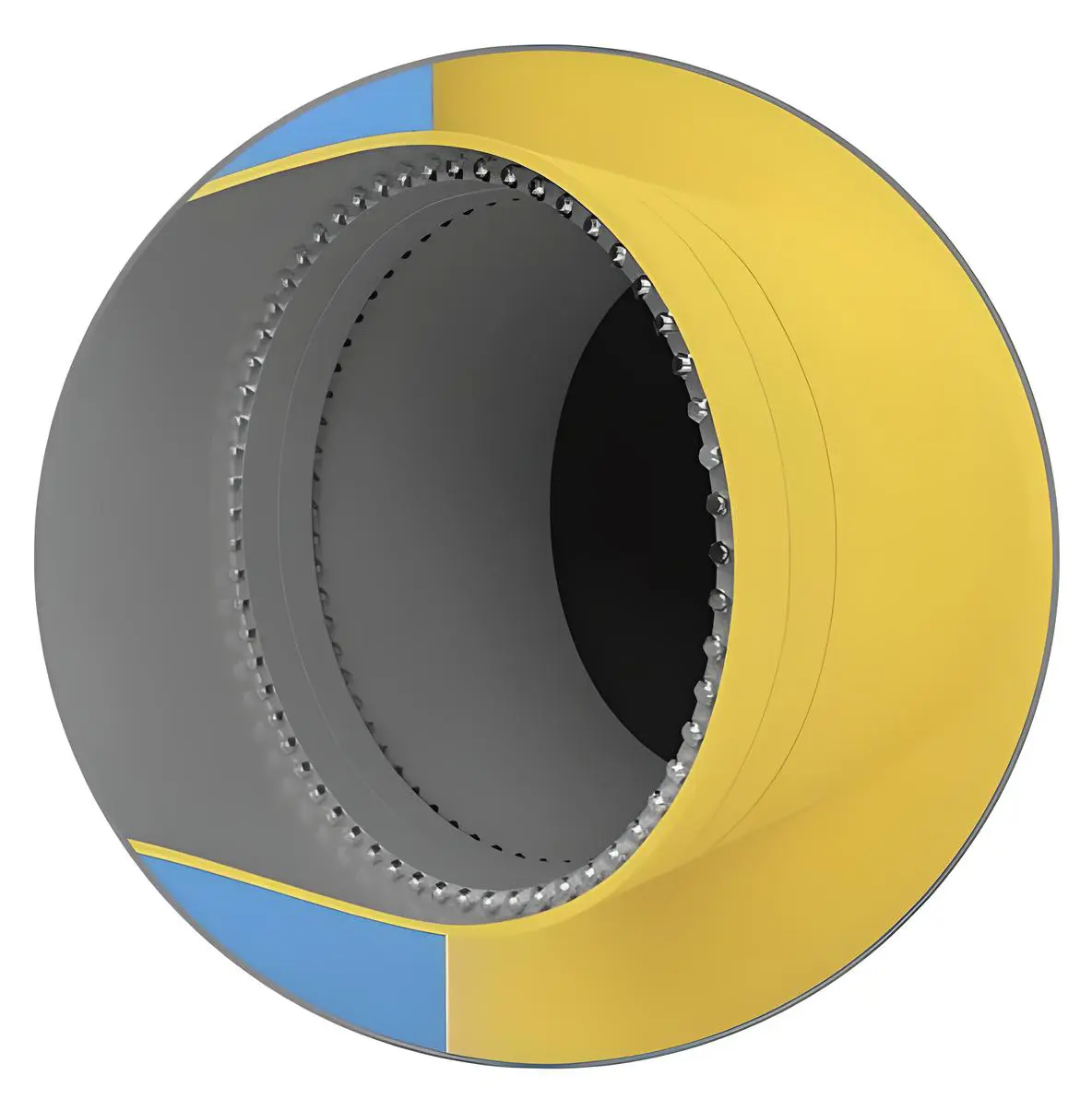
The CFC is another technology that appears unaffected by bolt preload loss/loosening. Compact flanges have been applied at a large scale, mainly in the Norwegian O&G industry, to assemble riser pipes and have a good track record for being maintenance free. Riser pipes in Norwegian waters are connected to floating O&G structures such as storage platforms and are subjected to high dynamic loads. Despite the harsh environment, no occurrences of leakage or failure of CFCs have been recorded. Typically, the connections in riser pipes would be installed horizontally and would not be subjected to large shear forces. However, current loadings on riser pipes will also result in shear loading on the connections. However, if its “static” connection can be maintained, these shear forces would not be acting on the bolts but rather on the connection as a whole, as it would with welded connections. The static connection will reduce the risk of reduced fatigue life of the bolts; however, the welds of the flange plates might still be subjected to added fatigue damage. So far, there are no examples in the literature of studies investigating fatigue in vertically mounted CFCs. TP-Products [97], the company that manufactures ring flanges based on the CFC technology, has designed a version that could be applied to FOWT foundations [98], as shown in Figure 8.
A patent is in place for CFCs, which may limit its use in the FOW industry, as is the case for O&G, where it is mainly used in Norway but hasn’t seen large scale use in other regions [23]. The current CFC design for FOWT foundations has the flange plates on the inside of the tubulars, which mitigates the risk of corrosion and eliminates the need for Remotely Operated Vehicles (ROV) for inspection and maintenance of the bolted connections. Of course, having standard ring flanges on the inside of the tubulars would also mitigate corrosion of the bolts, however, these would still be subject to the risk of bolt loosening.
Given its good track record in offshore O&G, the CFC is potentially a suitable low maintenance bolted connection type for FOWT foundations. However, adopting technologies that have been successfully applied in offshore O&G for FOW applications should be done with caution. The example of failing grouted connections in monopiles for bottom-fixed OWTs [99], has shown that O&G technologies do not always readily transfer to offshore wind. The diameters of structural members of MW-scale FOWT foundations will be bigger than those of riser pipes. Furthermore, there are no examples of floating O&G structures with bolted connections in the main load bearing components, other than risers. Without offshore experience, it is unclear how structural couplings and vibrations from the operating WTG will affect bolted connections in FOWT foundations.
 |
 |
|---|
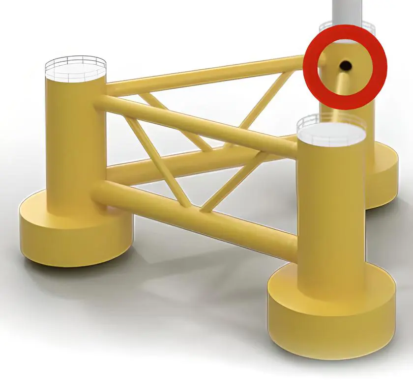
Figure 8. Compact Flange Connection (CFC) for FOWT foundations [97]. The red circle in the left-hand image indicates the blown-up detail in the right-hand image.
Furthermore, to make certain that all bolt holes and flanges line up perfectly for the various structural members at the assembly stage, highly precise fabrication will be required, and space for tolerances is limited. Any of the flanges or bolt holes that do not line up will result in delays and extra costs. For example, temperature fluctuations may cause tubulars to expand or contract, causing potential problems with the lining up of the different foundation components. FOWT foundations designed for 15–20 MW turbines may have braces that could reach lengths of up to 60 m. Such large dimensions will increase the risk of components not lining up perfectly during assembly. Furthermore, GW-scale FOW projects may include up to 60 FOWT foundations. Each foundation could include up to 12 bolted connections for the assembly of braces with floatation columns. Meaning there would be over 700 bolted connections and several thousand bolts per project, each requiring precise tolerances. Consequently, manufacturing quality will need to be up to very high standards. To ensure the successful assembly of the FOWT foundation, the tolerances of bolt holes may need to be increased compared to current practices. However, this may have a negative effect on the fatigue life of the connections, and further research to determine the limits of tolerances may be required. Increasing tolerances may also result in non-compliance with current standards and perhaps may require adaptations of the standards.
Furthermore, effective structural health monitoring methods to monitor preload, preferably remotely, will need to be available if bolted connections for FOWT foundations will be applied at commercial scale FOW projects. Methods such as those proposed by Valdez et al. [30] could be useful for monitoring bolt preload on FOWT foundations. However, their method was only applied to fixed OWT structures and only with applied wind loads. Further research would be required to determine the suitability of such monitoring methods for MW-scale FOWT foundations.
An alternative assembly method, perhaps less affected by tight tolerances, is assembly with pinned connections. The use of pinned connections has been demonstrated with the TetraSpar demonstrator [100,101], which has successfully been operational offshore for several years at the time of writing. Similar fast assembly times as can be achieved with bolted connections were demonstrated with the assembly of the TetraSpar demonstrator.
To gain confidence in bolted connections for the assembly of FOWT foundations, real-world data from offshore operations will be crucial. Both FOW developers and financial institutions backing FOW projects will need to be satisfied that the technology can be reliably deployed at a commercial scale. To achieve this, FOWT foundations with bolted connections will first need to be successfully demonstrated offshore with MW-scale prototypes. The Culzean project, and a second demonstration project planned by Ocergy with a foundation for a 15 MW turbine [102], are eagerly awaited by the industry, but realistically, these projects will need to show at least several years of successful operation to satisfy confidence.
Nonetheless, CFCs and the C1 Wedge Connection appear to have potential as an alternative to welded connections.
11. Conclusions
This study investigated the suitability of bolted connections as an assembly method for FOWT foundations. Using bolted connections for the assembly of FOWT foundations has potential benefits compared to the more conventional method of welding. Bolted connections have the following potential advantages:
-
-
Significantly shorter assembly time compared to welding.
-
-
Simplified assembly process compared to welding.
-
-
Applications with bolted connections in offshore O&G have been shown to be reliable and robust.
-
-
Potential reduction of CAPEX compared to welding.
Bolted connections are used in countless practical applications in every facet of daily life; however, they have not yet been used for the assembly of large structural components of FOWT foundations. Bolted connections have the following potential disadvantages:
-
-
Dynamic structural loads combined with environmental loads of FOWT foundations increase the potential for bolt loosening and fatigue, and consequently bolt failure.
-
-
Corrosion and temperature fluctuations also have negative impacts on bolt performance.
-
-
In offshore O&G, bolted connections have only been applied for the assembly of riser pipes, but not for the assembly of large load-bearing structural members of floating structures.
-
-
Bolted connections will require regular inspections and potentially regular re-tightening.
The following research gaps have been identified with this literature review:
-
-
Research on the effects of six-DOF dynamic loading and shear forces on the fatigue life of bolted connections in structural members of FOWT foundations. This includes both numerical and experimental research.
-
-
Research on bolt loosening in bolted connections of structural members in FOWT foundations.
-
-
Increased tolerances may be required to ensure the successful assembly of large structural members of FOWT foundations with bolted connections. The effects of increased tolerances on fatigue life could require additional research and perhaps adaptation of the international standards.
-
-
Adequate remote structural health monitoring methods for FOWT foundations with bolted connections.
-
-
The health and safety of maintenance technicians in confined spaces with difficult accessibility inside FOWT foundations with bolted connections has not been adequately addressed.
-
-
Analysis of real-world data of MW-scale offshore demonstrators with bolted connections. Of course, currently, no such data is available as there are no such offshore demonstrators yet. However, both the research community and the FOW industry would benefit immensely if such data were made public when it becomes available.
Regular ring flanges, as are currently used for connections between WTG towers and offshore wind foundations, are unlikely to be a suitable assembly method for FOWT foundations. These types of flanges are not designed to handle large shear forces and tend to be subject to bolt loosening. Despite the disadvantages mentioned above, the CFC has a good track record of low maintenance and reliability, and the C1 Wedge Connection has demonstrated the ability to maintain preload under external loads during testing. Both types of connections could be considered alternatives to welding for the assembly of FOWT foundations. However, their reliability as an application in FOW will need to be demonstrated offshore to gain confidence in the technology.
Acknowledgments
The authors would like to acknowledge David Keane, Michael Oyinlola, and Mario Marinero, all in ESB, for their comments on the draft article.
Author Contributions
A.M.: Investigation, Data Curation, Writing—Original Draft Preparation. N.B.: Investigation, Data Curation, Visualisation, Writing—Review & Editing. A.O.: Conceptualization, Investigation, Data Curation, Writing—Review & Editing, Supervision, Project Administration, Funding Acquisition.
Ethics Statement
Not applicable.
Informed Consent Statement
Not applicable.
Data Availability Statement
Data will be made available on request.
Funding
This research received no external funding.
Declaration of Competing Interest
The authors declare that they have no known competing financial interests or personal relationships that could have appeared to influence the work reported in this paper.
References
- Offshorewind-biz. TotalEnergies’ Floating Offshore Wind Project to Power UK Oil & Gas Platform. Available online: https://www.offshorewind.biz/2024/08/29/totalenergies-floating-offshore-wind-project-to-power-uk-oil-gas-platform/#:~:text=France%E2%80%99s%20TotalEnergies%20plans%20to%20launch%20a%20floating%20offshore,220%20kilometres%20off%20the%20eastern%20coast%20of (accessed on 22 October 2025). [Google Scholar]
- Ocergy. OCG Wind Sustainable Offshore Solutions. Available online: https://www.ocergy.com/ocg-wind (accessed on 22 October 2025). [Google Scholar]
- Principle Power. The WindFloat. Available online: https://www.principlepower.com/windfloat (accessed on 22 October 2025). [Google Scholar]
- Wu X, Hu Y, Li Y, Yang J, Duan L, Wang T, et al. Foundations of offshore wind turbines: A review. Renew. Sustain. Energy Rev. 2019, 104, 379–393. doi:10.1016/j.rser.2019.01.012. [Google Scholar]
- Edwards EC, Holcombe A, Brown S, Ransley E, Hann M, Greaves D. Evolution of floating offshore wind platforms: A review of at-sea devices. Renew. Sustain. Energy Rev. 2023, 183, 113416. doi:10.1016/j.rser.2023.113416. [Google Scholar]
- Mehmanparast A, Lotfian S, Vipin PS. A Review of Challenges and Opportunities Associated with Bolted Flange Connections in the Offshore Wind Industry. Metals 2020, 10, 732. doi:10.3390/met10060732. [Google Scholar]
- Lochan S, Mehmanparast A, Wintle J. A review of fatigue performance of bolted connections in offshore wind turbines. Procedia Struct. Integr. 2019, 17, 276–283. doi:10.1016/j.prostr.2019.08.037. [Google Scholar]
- Nordlock. What Is Preload and Why Is It Important? Available online: https://www.nord-lock.com/learnings/bolting-tips/2025/what-is-preload-and-why-is-it-important/ (accessed on 22 October 2025). [Google Scholar]
- DNV-ST-0126; Support Structures for Wind Turbines. Det Norske Veritas: Høvik, Norway, 2021. [Google Scholar]
- Braithwaite J, Goenaga IG, Tafazzolimoghaddam B, Mehmanparast A. Sensitivity analysis of friction and creep deformation effects on preload relaxation in offshore wind turbine bolted connections. Appl. Ocean Res. 2020, 101, 102225. doi:10.1016/j.apor.2020.102225. [Google Scholar]
- Braithwaite J, Mehmanparast A. Analysis of Tightening Sequence Effects on Preload Behaviour of Offshore Wind Turbine M72 Bolted Connections. Energies 2019, 12, 4406. doi:10.3390/en12234406. [Google Scholar]
- Karlsen Ø, Lemu HG. Comparative study on loosening of anti-loosening bolt and standard bolt system. Eng. Fail. Anal. 2022, 140, 106590. doi:10.1016/j.engfailanal.2022.106590. [Google Scholar]
- Ziegler L, Gonzalez E, Rubert T, Smolka U, Melero JJ. Lifetime extension of onshore wind turbines: A review covering Germany, Spain, Denmark, and the UK. Renew. Sustain. Energy Rev. 2018, 82, 1261–1271. doi:10.1016/j.rser.2017.09.100. [Google Scholar]
- Annoni A, Johnston C, Mehmanparast A. Fatigue life analysis of threaded connections in offshore wind turbines. Appl. Ocean Res. 2024, 153, 104287. doi:10.1016/j.apor.2024.104287. [Google Scholar]
- Ji X, Zou T, Bai X, Niu X, Tao L. Fatigue assessment of flange connections in offshore wind turbines under the initial flatness divergence. Front. Energy Res. 2023, 11, 1127957. doi:10.3389/fenrg.2023.1127957. [Google Scholar]
- Liu M, Geng R, Wang J, Li Y, Long K, Ding W, et al. The Investigation of Various Flange Gaps on Wind Turbine Tower Bolt Fatigue Using Finite-Element Method. Appl. Sci. 2024, 14, 3670. doi:10.3390/app14093670. [Google Scholar]
- Zou T, Niu X, Ji X, Li M, Tao L. The impact of initial imperfections on the fatigue assessment of tower flange connections in floating wind turbines: A review. Front. Mar. Sci. 2022, 9, 1063120. doi:10.3389/fmars.2022.1063120. [Google Scholar]
- Madsen C, Kragh-Poulsen J, Thage K, Andreassen M. Analytical and numerical investigation of bolted steel ring flange connection for offshore wind monopile foundations. IOP Conf. Ser. Mater. Sci. Eng. 2017, 276, 012034. doi:10.1088/1757-899X/276/1/012034. [Google Scholar]
- C1 Connections. The C1 Wedge Connection. Available online: https://c1connections.com/ (accessed on 23 October 2025). [Google Scholar]
- Creusen KEY, Misios G, Winkes JS, Veljkovic M. Introducing the C1 Wedge Connection. Steel Constr. 2021, 15, 13–25. doi:10.1002/stco.202100039. [Google Scholar]
- Cheng L, Yang F, Winkes JS, Veljkovic M. The C1 wedge connection in towers for wind turbine structures, tensile behaviour of a segment test. Eng. Struct. 2023, 282, 115799. doi:10.1016/j.engstruct.2023.115799. [Google Scholar]
- Cheng L, Yang F, Seidel M, Veljkovic M. FE-assisted investigation for mechanical behaviour of connections in offshore wind turbine towers. Eng. Struct. 2023, 285, 116039. doi:10.1016/j.engstruct.2023.116039. [Google Scholar]
- Lassesen S, Eriksen T, Teller F. NORSOK L-005—Compact Flanged Connections (CFC): The New Flange Standard. In Proceedings of the ASME Pressure Vessels and Piping Conference, Vancouver, BC, Canada, 4–8 August 2002; PVP2002-1097, pp. 189–195. doi:10.1115/PVP2002-1097. [Google Scholar]
- Lutkiewicz P, Robertson D, Lee S. Subsea Flanges, Comparison Between Conventional API 6A Type 6BX Flange and SPO Compact Flange Designs. In Proceedings of the ASME Pressure Vessels and Piping Conference, Minneapolis, MN, USA, 19–24 July 2020; PVP2020-21372, V005T05A003. doi:10.1115/PVP2020-21372. [Google Scholar]
- Croccolo D, De Agostinis M, Fini S, Mele M, Olmi G, Scapecchi C, et al. Failure of Threaded Connections: A Literature Review. Machines 2023, 11, 212. doi:10.3390/machines11020212. [Google Scholar]
- Javadi Y, Mills B, MacLeod C, Lines D, Abad F, Lotfian S, et al. Phased Array Ultrasonic Method for Robotic Preload Measurement in Offshore Wind Turbine Bolted Connections. Sensors 2024, 24, 1421. doi:10.3390/s24051421. [Google Scholar]
- He X, She T. A New Identification Method for Bolt Looseness in Wind Turbine Towers. Shock Vib. 2019, 2019, 6056181. doi:10.1155/2019/6056181. [Google Scholar]
- Haute CV, Pire T. Maintenance intervals for MP-TP bolted connections—A case study. Results Eng. 2020, 5, 100064. doi:10.1016/j.rineng.2019.100064. [Google Scholar]
- Fernando S. Tension Control Bolts—Explained. Hobson Engineering Company Pty. Ltd. Available online: https://cdn.hobson.com.au/documents/article-tension-control-bolts-explained.pdf (accessed on 23 October 2025). [Google Scholar]
- Valdez R, Palacios E, Tutivén C, Vidal Y. Bolt-loosening detection in offshore wind turbines’ jacket-type supports. Struct. Health Monit. 2024, 24, 2941–2957. doi:10.1177/14759217241268522. [Google Scholar]
- Adedipe O, Brennan F, Kolios A. Review of corrosion fatigue in offshore structures: Present status and challenges in the offshore wind sector. Renew. Sustain. Energy Rev. 2016, 61, 141–154. doi:10.1016/j.rser.2016.02.017. [Google Scholar]
- Wang T, Liang G, Liu Y. Mechanical performance analysis of bolt connections for wind turbine towers after corrosion. Structures 2025, 71, 108202. doi:10.1016/j.istruc.2025.108202. [Google Scholar]
- Schaumann P, Eichstädt R. Fatigue Assessment of High-Strength Bolts with Very Large Diameters in Substructures. In Proceedings of the International Ocean and Polar Engineering Conference, Kona, HI, USA, 21–26 June 2015; pp. 1–6. [Google Scholar]
- Zhang J, Heng J, Dong Y, Baniotopoulos C, Yang Q. Coupling multi-physics models to corrosion fatigue prognosis of high-strength bolts in floating offshore wind turbine towers. Eng. Struct. 2024, 301, 117309. doi:10.1016/j.engstruct.2023.117309. [Google Scholar]
- Gaidai O, Yakimov V, Wang F, Zhang F, Balakrishna R. Floating wind turbines structural details fatigue life assessment. Sci. Rep. 2023, 13, 16312. doi:10.1038/s41598-023-43554-4. [Google Scholar]
- Fatemi A, Yang L. Cumulative fatigue damage and life prediction theories: A survey of the state of the art for homogeneous materials. Int. J. Fatigue 1998, 20, 9–34. doi:10.1016/S0142-1123(97)00081-9. [Google Scholar]
- DNV-RP-C203; Fatigue Design of Offshore Steel Structures. Det Norske Veritas: Høvik, Norway, 2024. [Google Scholar]
- Eccles B. Fatigue Failure of Bolts. Available online: https://www.boltscience.com/pages/fatigue-failure-of-bolts.pdf (accessed on 30 November 2025). [Google Scholar]
- Schaumann P, Böhm M, Schürmann K. Improvements in the fatigue design of support structures for offshore wind turbines. Steel Constr. 2021, 14, 74–82. doi:10.1002/stco.202000060. [Google Scholar]
- Liu J, Ma Y, Chen J, Ji C, Su D. Research on Fatigue Assessment of the Flange Bolts Connection of Wind Turbine Based on Finite Element Analysis. In Proceedings of the 2016 2nd Workshop on Advanced Research and Technology in Industry Applications (WARTIA), Dalian, China, 14–15 May 2016; pp. 435–440. doi:10.2991/wartia-16.2016.87. [Google Scholar]
- Gao S, Liu J, Wang X, Zhao C, Wu F. Fatigue Damage Evaluation of High-strength Bolt for Tower of Wind Turbine. Eur. J. Comput. Mech. 2025, 33, 583–606. doi:10.13052/ejcm2642-2085.3363. [Google Scholar]
- Kikuchi Y, Ishihara T. Fatigue prediction of wind turbine tower considering the effect of high-tension bolt failure. Eng. Fail. Anal. 2025, 174, 109494. doi:10.1016/j.engfailanal.2025.109494. [Google Scholar]
- Johnston C, Doré M. Comparison of the Fatigue Performance of Galvanised M72 Bolts with Design Standard Recommendations. In Proceedings of the International Conference on Ocean, Offshore, and Arctic Engineering, Virtual, Online, 21–30 June 2021; OMAE2021-62758, V003T03A006. doi:10.1115/OMAE2021-62758. [Google Scholar]
- Eichstädt R. Fatigue Assessment of Large-Size Bolting Assemblies for Wind Turbine Support Structures. Ph.D. Thesis, Gottfried Wilhelm Leibniz Universität, Hannover, Germany, 2019. doi:10.15488/5157. [Google Scholar]
- Rincón-Casado A, Juliá JM, García-Vallejo D, Domínguez J. Experimental estimation of the residual fatigue life of in-service wind turbine bolts. Eng. Fail. Anal. 2022, 141, 106658. doi:10.1016/j.engfailanal.2022.106658. [Google Scholar]
- ISO 898-1:2013; Mechanical Properties of Fasteners Made of Carbon Steel and Alloy Steel. International Organization for Standardization: Geneva, Switzerland, 2013. [Google Scholar]
- ISO 12944-5:2019; Paints and Varnishes—Corrosion Protection of Steel Structures by Protective Paint Systems. International Organization for Standardization: Geneva, Switzerland, 2019. [Google Scholar]
- ISO 12473:2017; General Principles of Cathodic Protection in Seawater. International Organization for Standardization: Geneva, Switzerland, 2017. [Google Scholar]
- ISO 16047:2005; Fasteners—Torque/Clamp Force Testing. International Organization for Standardization: Geneva, Switzerland, 2005. [Google Scholar]
- ISO 19902:2020; Petroleum and Natural Gas Industries—Fixed Steel Offshore Structures. International Organization for Standardization: Geneva, Switzerland, 2020. [Google Scholar]
- VDI 2230; Systematic Calculation of Highly Stressed Bolted Joints. Verein Deutscher Ingenieure: Düsseldorf, Germany, 2015. [Google Scholar]
- BS 7608:2014; Guide to Fatigue Design and Assessment of Steel Products. British Standard Institution: London, UK, 2014. [Google Scholar]
- EN 1993-1-9:2025; Eurocode 3: Design of Steel Structures—Part 1-9: Fatigue. European Committee for Standardization (CEN): Brussels, Belgium, 2025. [Google Scholar]
- EN 1090-2:2018+A1:2024; Execution of Steel Structures and Aluminium Structures—Part 2: Technical Requirements for Steel Structures. European Committee for Standardization (CEN): Brussels, Belgium, 2024. [Google Scholar]
- ASME PCC-1-2013; Guidelines for Pressure Boundary Bolted Flange Joint Assembly (BFJA). The American Society of Mechanical Engineers: New York, NY, USA, 2013. [Google Scholar]
- IEC 61400-3-2; Wind Energy Generation Systems—Part 3-2: Design Requirements for Floating Offshore Wind Turbines. International Electrotechnical Commission: Geneva, Switzerland, 2025. [Google Scholar]
- DNV-ST-0119; Floating Wind Turbine Structures. Det Norske Veritas: Høvik, Norway, 2021. [Google Scholar]
- American Bureau of Shipping. Guide for Building and Classing—Floating Offshore Wind Turbines; American Bureau of Shipping: Spring, TX, USA, 2025. [Google Scholar]
- LR-RP-003; Recommended Practice for Floating Offshore Wind Turbine Support Structures. Lloyd’s Register: London, UK, 2024. [Google Scholar]
- LR-RU-003; Rules for the Classification of Offshore Units. Lloyd’s Register: London, UK, 2024. [Google Scholar]
- NR572; Classification and Certification of Floating Offshore Wind Turbines. Bureau Veritas: Paris, France, 2024. [Google Scholar]
- NR445; Rules for the Classification of Offshore Units. Bureau Veritas: Paris, France, 2025. [Google Scholar]
- Jukes P. Fabrication Welding Processes. In Encyclopedia of Maritime and Offshore Engineering; Carlton J, Jukes P, Choo YS, Eds.; Wiley: Hoboken, NJ, USA, 2018; pp. 1–9. doi:10.1002/9781118476406.emoe148. [Google Scholar]
- Turan E, Koçal T, Ünlügençoğlu K. Welding Technologies in Shipbuilding Industry. Online J. Sci. Technol. 2011, 1, 24–30. [Google Scholar]
- Mvola B, Kah P. Effects of shielding gas control: Welded joint properties in GMAW process optimization. Int. J. Adv. Manuf. Technol. 2017, 88, 2369–2387. doi:10.1007/s00170-016-8936-2. [Google Scholar]
- Gidiagba JO, Olalere BI, Fawole AA, Egbokhaebho BA, Ehiobu NN, Okparaeke JI. Review of Advanced Welding and Testing for Safety in Offshore Oil and Gas. Mater. Corros. Eng. Manag. 2023, 4, 37–43. doi:10.26480/macem.02.2023.37.43. [Google Scholar]
- Plessis JD. Welding of Offshore Structures. Available online: https://www.spesmet.co.za/wp-content/uploads/2016/09/Welding-of-Offshore-structure-2012.pdf (accessed on 25 November 2025). [Google Scholar]
- Afriansyah A, Arifin A. Dissimilar metal welding using Shielded Metal Arc Welding: A Review. Technol. Rep. Kansai Univ. 2020, 62, 1935–1948. [Google Scholar]
- Zavvar E, Rosa-Santos P, Ghafoori E, Taveira-Pinto F. Analysis of tubular joints in marine structures: A comprehensive review. Mar. Struct. 2025, 99, 103702. doi:10.1016/j.marstruc.2024.103702. [Google Scholar]
- Hyundai Welding. Welding Solution for the Offshore Industry. Available online: https://hyundaipns.com/data/file/download/brochures/Hyundai_Welding_Offshore_Brochure_2024_eng.pdf (accessed on 25 November 2025). [Google Scholar]
- Gyasi EA. Welding Processes of Metals for Offshore Environment: Underwater Welding; Lappeenranta-Lahti Univ. Technol. LUT: Lappeenranta, Finland, 2019; ISBN 978-952-335-433-3. [Google Scholar]
- Świerczyńska A, Varbai B, Pandey C, Fydrych D. Exploring the trends in flux-cored arc welding: Scientometric analysis approach. Int. J. Adv. Manuf. Technol. 2024, 130, 87–110. doi:10.1007/s00170-023-12682-6. [Google Scholar]
- AWS D1.1; Structural Welding Code—Steel. American Welding Society: Doral, FL, USA, 2025. [Google Scholar]
- Spangineer. GMAW Weld Area. Available online: https://commons.wikimedia.org/wiki/File:GMAW_weld_area.svg (accessed on 3 December 2025). [Google Scholar]
- Marcelochal. SMAW Area Diagram. Available online: https://commons.wikimedia.org/wiki/File:SMAW_area_diagram.svg (accessed on 3 December 2025). [Google Scholar]
- Jones R. FCAW Diagram. Available online: https://commons.wikimedia.org/wiki/File:FCAW_diagram.svg (accessed on 3 December 2025). [Google Scholar]
- Duk. GTAW. Available online: https://commons.wikimedia.org/wiki/File:GTAW.svg (accessed on 3 December 2025). [Google Scholar]
- Conte R, Rodríguez Izquierdo D, Gagliardi F. Submerged arc welding process: a numerical investigation of temperatures, displacements, and residual stresses in ASTM A516-Gr70 corner joined samples. Int. J. Adv. Manuf. Technol. 2023, 127, 5437–5448. doi:10.1007/s00170-023-11908-x. [Google Scholar]
- Kitagawa Y, Kawasaki H. Recent development of high-strength and tough welding consumables for offshore structures. Kobe Steel Eng. Rep. 2013, 63, 16–21. [Google Scholar]
- Chen B-Q, Liu K, Xu S. Recent Advances in Aluminum Welding for Marine Structures. J. Mar. Sci. Eng. 2024, 12, 1539. doi:10.3390/jmse12091539. [Google Scholar]
- Scholl S, Schütz J, Lenhard S, Lehnert T, Staudt T, Schütz W. Development of Heavy Plates for High-Energy Welding of Monopiles for the Construction of Offshore Wind Energy Plants. In Proceedings of the 3rd International Symposium on the Recent Developments in Plate Steels, Vail, CO, USA, 2–5 June 2024. doi:10.33313/300/018. [Google Scholar]
- Okenyi V, Afazov S, Mansfield N, Balakrishnan J, Kyffin W, Siegkas P, et al. Submerged Arc Welding of S355G10+M Steel: Analyzing Strength, Distortion, Residual Stresses, and Fatigue for Offshore Wind Applications. Fatigue Fract. Eng. Mater. Struct. 2025, 48, 3859–3878. doi:10.1111/ffe.70010. [Google Scholar]
- Mathers G. Job Knowledge 97: Welding Costs. Available online: https://www.twi-global.com/technical-knowledge/job-knowledge/welding-costs-continued-097 (accessed on 27 November 2025). [Google Scholar]
- The Welding Institute. Standard Data for Arc Welding. Available online: https://www.twi-global.com/pdfs/best-practice-guides/bpsdawv1.pdf (accessed on 27 November 2025). [Google Scholar]
- O’Brien A. Welding Handbook. Volume 2: Welding Processes, Part 1, 9th ed.; Amer Welding Society: Miami, FL, USA, 2004; ISBN 978-0871717290. [Google Scholar]
- Corigliano P, Crupi V. Review of Fatigue Assessment Approaches for Welded Marine Joints and Structures. Metals 2022, 12, 1010. doi:10.3390/met12061010. [Google Scholar]
- Musolino J, Shi X-H, Chen B-Q. Numerical Investigation on Residual Stress and Distortion in Welded Joints of Offshore Platform Structures. J. Mar. Sci. Eng. 2025, 13, 1941. doi:10.3390/jmse13101941. [Google Scholar]
- DNV-OS-C401; Fabrication and Testing of Offshore Structures. Det Norske Veritas: Høvik, Norway, 2025. [Google Scholar]
- Poutiainen E. Design Guides for Engineering Joints in Offshore Conditions: Bolt, Weld, and Interference Joints. Master’s Thesis, Lappeenranta–Lahti University of Technology LUT, Lappeenranta, Finland, 2022. Available online: https://lutpub.lut.fi/handle/10024/164740 (accessed on 23 October 2025). [Google Scholar]
- ISO 4042:2018; Fasteners—Electroplated Coating Systems. International Organization for Standardization: Geneva, Switzerland, 2018. Available online: https://shop.standards.ie/en-ie/standards/iso-4042-2018-614129_saig_iso_iso_2624797 (accessed on 23 October 2025). [Google Scholar]
- Chung PP, Wang J, Durandet Y. Deposition processes and properties of coatings on steel fasteners—A review. Friction 2019, 7, 389–416. doi:10.1007/s40544-019-0304-4. [Google Scholar]
- Oral History Research Unit, Bournemouth University. Building the Ship. Available online: https://histru.bournemouth.ac.uk/Oral_History/Talking_About_Technology/shipbuilding/building_the_ship.htm (accessed on 23 October 2025). [Google Scholar]
- ORE Catapult. Advanced Manufacturing of Substructure Components. Available online: https://fowcoe.co.uk/industry-insights/reports/advanced-manufacturing-of-substructure-components/ (accessed on 23 October 2025). [Google Scholar]
- Zavvar E, Rosa-Santos P, Taveira-Pinto F, Ghafoori E. Lifetime extension of offshore support structures of wind turbines: A review. Renew. Sustain. Energy Rev. 2025, 217, 115788. doi:10.1016/j.rser.2025.115788. [Google Scholar]
- Rinaldi G, Thies PR, Johanning L. Current Status and Future Trends in the Operation and Maintenance of Offshore Wind Turbines: A Review. Energies 2021, 14, 2484. doi:10.3390/en14092484. [Google Scholar]
- Ge M, Li L, Meng H, Kai L. Offshore Wind Turbine Maintenance and Operation; Springer: Singapore, 2025; pp. 179–212. doi:10.1007/978-981-96-2175-0_6. [Google Scholar]
- Tp-products. Wind Power Flanges. Available online: https://tp-products.com/wind-power-flanges/ (accessed on 23 October 2025). [Google Scholar]
- Lassesen S. The Use of Bolted Joints in Primary Load Bearing Structures. Poster Presentation PO068. In Proceedings of the Annual Wind Europe Conference, Copenhagen, Denmark, 25–27 April 2023. [Google Scholar]
- Gupta S, Stoddart E, Sanderson D, Morrison A. Condition Monitoring of Offshore Wind Turbines with Scour and Grout Damage in Monopile Foundations. In Proceedings of the SECED: Earthquake Risk and Engineering Towards a Resilient World, Cambridge, UK, 9–10 July 2015. [Google Scholar]
- Borg M, Jensen MW, Urquhart S, Andersen MT, Thomsen JB, Stiesdal H. Technical Definition of the TetraSpar Demonstrator Floating Wind Turbine Foundation. Energies 2020, 13, 4911. doi:10.3390/en13184911. [Google Scholar]
- Thomsen JB, Bergua R, Jonkman J, Robertson A, Mendoza N, Brown C, et al. Modeling the TetraSpar Floating Offshore Wind Turbine Foundation as a Flexible Structure in OrcaFlex and OpenFAST. Energies 2021, 14, 7866. doi:10.3390/en14237866. [Google Scholar]
- Offshorewind-biz. Project to Demonstrate 15+ MW Turbine on Ocergy’s Floating Platform Kicks Off. Available online: https://www.offshorewind.biz/2025/06/23/project-to-demonstrate-15-mw-turbine-on-ocergys-floating-platform-kicks-off/ (accessed on 23 October 2025). [Google Scholar]