Effects of Platform Motions on Dynamic Responses in a Floating Offshore Wind Turbine Blade

Effects of Platform Motions on Dynamic Responses in a Floating Offshore Wind Turbine Blade
Baoxuan Wang 1,2,* Jianwei Zhang 3,* Yue Chen 1 Huadan Zhu 1 Long Teng 1
Received: 11 October 2025 Revised: 30 October 2025 Accepted: 14 November 2025 Published: 19 November 2025

© 2025 The authors. This is an open access article under the Creative Commons Attribution 4.0 International License (https://creativecommons.org/licenses/by/4.0/).
1. Introduction
The development and utilization of offshore wind are regarded as one of the most significant ways to decarbonize power production and reduce greenhouse gas emissions. Thus, substantial efforts are being made to design wind turbines capable of capturing energy at sea. These turbines can be installed on fixed-bottom or floating foundations. For shallow waters and soft seabeds, fixed-bottom foundations are the most cost-effective option. Currently, most offshore wind turbines are of this bottom-fixed type, installed in waters less than 60 m deep. The installed substructures include monopiles, jackets (braced lattice frames), tripods, tripiles, and gravity foundations, which are fixed to the seabed [1,2,3]. In practice, fixed-bottom designs are usually regarded as the preferred substructures due to their ease of fabrication and installation, but more challenging sea states, water depths, and soil conditions may make them uneconomic. In this context, floating concepts are emerging as promising alternative solutions, which enable turbines to float and generate power further out to sea, where winds are stronger, as can be seen in Figure 1. These FOWTs are subjected to various environmental loads, such as wind, waves, and currents [4], and have complex 6-DOF motions under fully-coupled loadings involving aerodynamics, control systems, hydrodynamics, and structural dynamics [5,6].
According to [2], the hydrodynamic loads acting on the support structure of a fixed-bottom offshore wind turbine can affect the rotor–nacelle assembly (RNA) only indirectly. The indirect influence of hydrodynamic loads on the rotor–nacelle assembly is generally small and possibly negligible, depending on the dynamic characteristics of the support structure [2]. The designer may exclude consideration of the influence of hydrodynamic loads on the rotor–nacelle assembly if the effect of such loads can be demonstrated to be negligible.
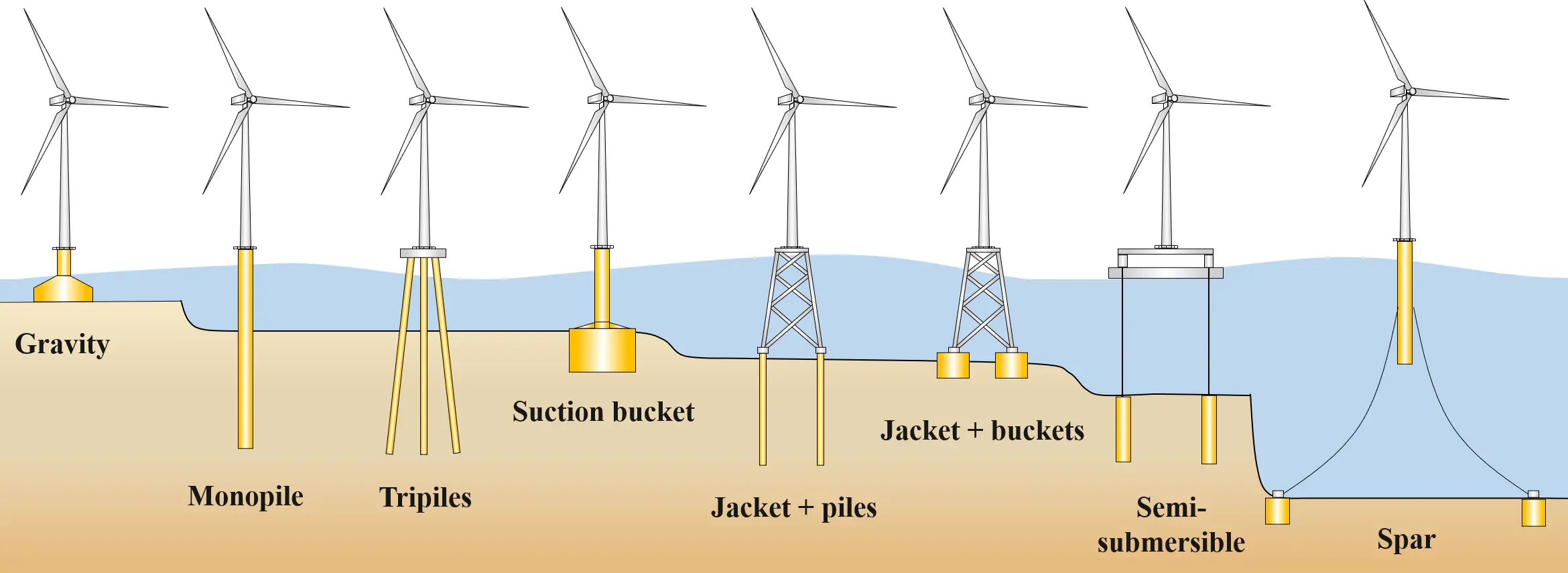
Figure 1. Sketches of common concepts for offshore wind turbine support structures from fixed to floating.
Compared with fixed-bottom offshore wind turbines, FOWTs with moving platforms face more complex and extreme environmental and operating conditions, which increase their damage risk and complexity. According to [5], the hydrodynamic and station-keeping system loads acting on the floating substructure of a FOWT can directly affect the tower and RNA as a consequence of the dynamic response of the support structure and are generally not negligible, but can be significant. FOWTs offer unique engineering challenges due to the coupling of platform mobility to aerodynamic loads on the turbine rotor [7,8,9,10,11,12,13].
Rotor blades are one of the most critical components of the wind turbine system, which are complex structures in terms of both geometric shape and composite layups [14]. Their design is a compromise between aerodynamic efficiency and structural strength [15,16]. In addition to requiring a series of efficient aerodynamic airfoils to propel generator-connected blades, they also need sufficient load-bearing capacity and durability to withstand extreme loads and required fatigue cycles.
The induced blade loading and motions resulting from waves and platform movement are important for the design process, but there have been few investigations conducted up to now. For instance, Johlas et al. [7] only investigated the floating platform effects on power generation. They found that among the 6-DOF motions, surge and pitch influence the rotor displacement and consequently the power generation of wind turbines. Papi and Bianchini [17] found that the maximum blade tip deflections for semi-submersible NREL 5 MW and IEA 15 MW reference FOWTs might increase when the 6-DOF platform motions were not constrained. According to the loads analysis of six 5-MW FOWT concepts performed by Robertson & Jonkman [18], the effect of platform motions on blade-root bending moments depends on the different types of FOWT concepts. They found that the wind turbine mounted on the ITI Energy barge was affected more by the waves than by the wind, and the DLC 1.1 for the ITI Energy barge system dominated the load results. For the spar buoy, it was found that the difference in blade-root bending moment for ultimate analysis from DLCs 1.1, 1.3, 1.4, and 1.5 between fixed-bottom and floating platforms was insignificant, while the platform motions decreased the blade-root bending moments for fatigue analysis from DLC 1.2 [19]. It should be noted that these past studies only focused on the normalized statistical results of flapwise and edgewise responses from various simulations, without paying attention to detailed time-varying blade structural responses under individual concrete load cases. To this end, this study will investigate the influences of platform motions on six load components at the blade root and blade-tip translational deflections quantitatively. By providing such a focused investigation, this work aims to deliver concrete data and insights that can guide the load calculation and structural design processes for FOWT blades. The remaining paper is structured as follows: Section 2 will briefly describe the methodology. In Section 3, the case study is presented, containing a description of the model, integrated analyses, a comparison of results, and a discussion. Concluding remarks are presented in Section 4. Additionally, the supplementary materials are provided at the end of the paper.
2. Methodology
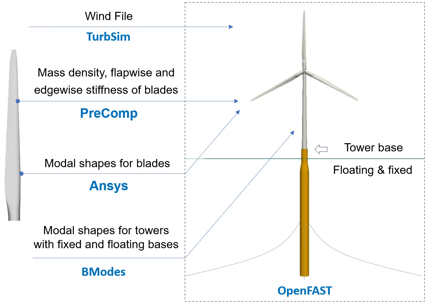
This study focuses on the global structural dynamic response of FOWT blades under fully coupled loads, and employs OpenFAST [20] to conduct integrated nonlinear aero-hydro-servo-elastic time-domain load simulations that consider aerodynamic, hydrodynamic, control, and electrical system (servo) dynamics, and structural (elastic) dynamics. Specifically, the simulated turbine is mounted on a spar-type floating platform. For comparison, a fixed-bottom (tower base) version is also replicated by disabling all platform displacements. In the full system FOWT modeling, four preprocessors are used to build input models for OpenFAST, as shown in Figure 2. Herein, TurbSim [21] is used to generate stochastic and full-field turbulent wind; PreComp [22] is used to compute span-variant structural properties for composite blades; Ansys [23] is used to calculate and derive modal shapes for blades; and BModes [24,25] is used to provide dynamically coupled tower modes for the fixed-bottom and floating configurations. The calculation of coupled blade structure responses is based on the assumed-mode method and Euler-Bernoulli beam theory.
3. Case Study
3.1. Blade Model
The blade structural model used in this study is consistent with the model employed in [3] and described in detail in [26], which is based on the reference model from [27]. This model was derived through a reverse structural design process from the publicly available distributed isotropic beam properties of the NREL 5-MW offshore wind turbine blade [28]. Specifically, the blade length is 61.5 m, and the maximum chord length is 4.652 m, which occurs at a spanwise position 15.85 m from the blade root. The blade contains two shear webs and two spar caps inside. Its constituent materials include uni-directional carbon reinforced polymer, glass reinforced polymer, foam, gelcoat, triaxial fabric, and biaxial fabric. Furthermore, the cantilevered hub-to-blade boundary condition (all degrees of freedom per node at the blade root are constrained) is employed in this work.
The blade structural dynamics can be calculated based on the linear normal mode superposition method and Euler-Bernoulli beam theory, by inputting the first three lowest blade modes computed by Ansys [23], mass per unit length, and flapwise and edgewise stiffness derived by PreComp [22] to the OpenFAST ElastoDyn module [20]. It can be found in Figure 3 that the first three mode shapes calculated are flapwise and edgewise bending modes, showing the so-called beam behaviour of a slender structure and the fact that the motions of the studied blade are dominated by bending. Given that the magnitude of blade torsion is much lower than that of bending deformation, the torsional mode is ignored in this work.
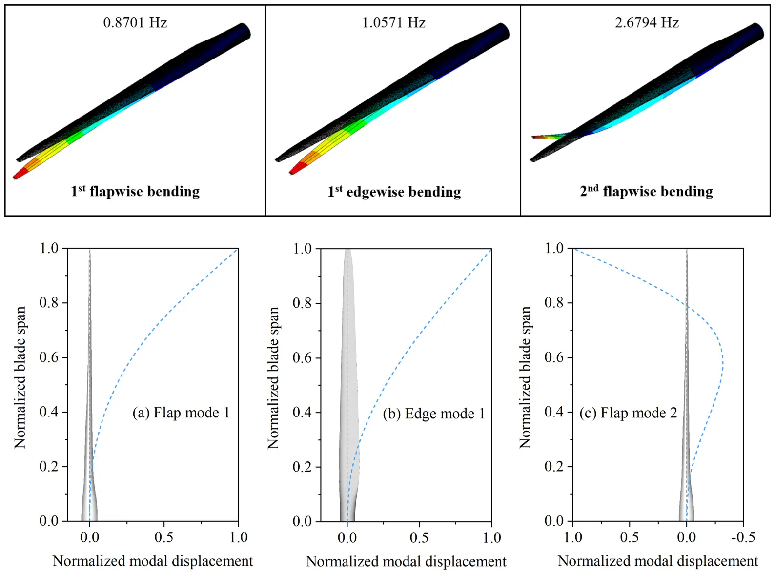
Figure 3. The first three modal frequencies and shapes of the nominal operating blade rotated at a rotor speed of 12.1 rpm: (a) 1st flap mode with the frequency of 0.8701 Hz; (b) 1st edge mode with the frequency of 1.0571 Hz; (c) 2nd flap mode with the frequency of 2.6794 Hz.
3.2. Full-System Model
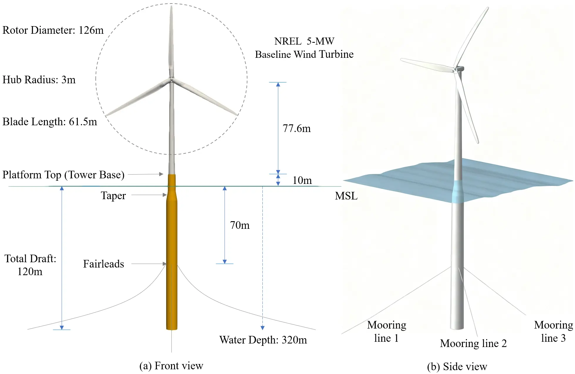
The offshore wind system used was the OC3-Hywind spar-type buoy, which was developed for use in the International Energy Agency (IEA) Offshore Code Comparison Collaborative (OC3) project [29], and supports NREL’s offshore 5-MW baseline turbine with the cut-in, rated, and cut-out wind speeds of 3 m/s, 11.4 m/s, and 25 m/s, respectively [27]. As observed in Figure 4, the “OC3-Hywind” system is composed of the NREL 5-MW prototype turbine (a conventional three-bladed upwind, variable-speed, variable blade-pitch-to-feather-controlled turbine), tower structure, spar-type buoy platform, and mooring systems. Additionally, 3 mooring lines with an included angle of 120 degrees are employed in this system to prevent the system from drifting; one of them is arranged in the nominal downwind direction. For more details about the system, refer to the Supplementary Materials. Table 1 lists the natural frequencies of the 6-DOF motions derived from the free decay simulations of this FOWT system, and these frequencies are consistent with the results from [1,13].
Table 1. Summary of natural frequencies derived from the free decay simulations of the FOWT (unit: Hz).
|
Motions |
Surge |
Sway |
Heave |
Yaw |
Pitch |
Roll |
|---|---|---|---|---|---|---|
|
Natural frequency |
0.0077 |
0.0077 |
0.0315 |
0.122 |
0.034 |
0.034 |
In order to achieve the research objectives of this study, the loads and motions of the wind turbine blade of the spar-type FOWT need to be compared to those of an equivalent fixed-bottom turbine. Thus, a fixed-bottom version of the FOWT is replicated by disabling all platform displacements at the tower base of the floating platform, meaning the tower base is clamped and the hydrodynamic loads are not applied. That is to say, in this work, the fixed-bottom model is created by constraining platform motions, and all other conditions are identical.
It is worth noting that since the computation of the tower modes depends on the boundary conditions of the tower, it is necessary to consider the influence of the platform flexibility on the stiffness of the substructure and the tower modes. In this work, BModes [24,25] was used to perform eigenanalysis and determine modal characteristics (eigenfrequencies and modal shapes) of the tower supported by fixed-bottom and floating platforms for comparison. Table 2 presents the natural frequencies of the first two eigenmodes of the support structure in fore-aft and side-side directions, with rigid and flexible tower-base boundary conditions. Corresponding mode shapes are illustrated in Figure 5. It can be seen that the fixed-bottom tower has a smaller natural frequency for each eigenmode compared to the tower with a floating base, which is consistent with the finding from [25]. Additionally, differences in modal shapes between the two towers are visible. Then, the modal shapes of the tower with a floating base are fitted by a sixth order polynomial whose fitting coefficients are input to the ElastoDyn module to take the effect of the floater on tower motions into account.
Table 2. Natural frequencies of tower with fixed-bottom and floating bases (unit: Hz).
|
Mode Shape |
1st Side-Side |
1st Fore-Aft |
2nd Side-Side |
2nd Fore-Aft |
|---|---|---|---|---|
|
Fixed-bottom |
0.3706 |
0.3756 |
1.9962 |
2.4926 |
|
Floating |
0.4777 |
0.4868 |
2.0523 |
2.5539 |
According to [30], eight load cases based on the statistics of 22 years of monitoring data from a site in the Dutch North Sea were established as possible environmental conditions, intended to represent load cases with high occurrence probabilities during normal power generation and a load case involving maximum wind speed during parking conditions. Table 3 lists the characteristic parameters of the involved turbulent wind and irregular waves. Moreover, the sub-surface current model with a sea surface velocity of 0.6 m/s is used to generate the sea current velocity profile. The turbulent wind field is created by TurbSim [21], which can use statistical models to numerically simulate time-varying three-component wind-speed vectors at points in a two-dimensional vertical rectangular grid that is fixed in space and produce wind output compatible with OpenFAST [20]. The grid size is set to 31 × 31 points comprising an area of 175 × 175 m2, and the center point of the grid is at the hub height. The IEC Kaimal model [31] was selected to generate full-field turbulent wind by applying the inverse Fourier transform to the wind-component power spectral densities. And the normal wind profile with the power law exponent of 0.14 as specified in [2] is employed. The JONSWAP irregular wave spectrum was used to generate wave-elevation time series [32]. The sub-surface current model (see [20]) is used to generate the sea current velocity profile. Furthermore, the employed wind, wave, and current are unidirectional, normal to the rotor plane, located in the middle of two mooring lines, with the remaining one mooring line pointing towards the downwind direction.
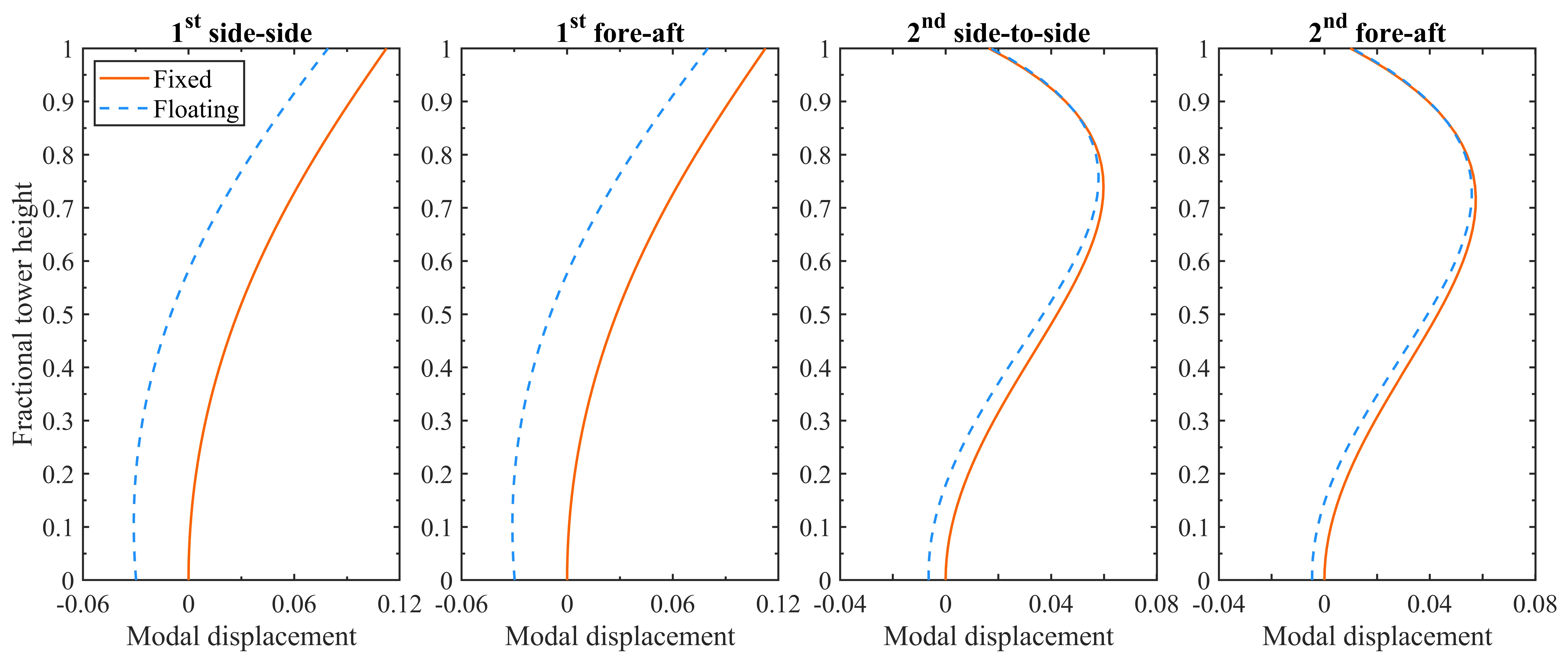
Table 3. Load cases set for fixed-bottom and floating wind turbines.
|
Load Case (LC) |
URef (m/s) |
TI (%) |
Hs (m) |
Tp (s) |
Note * |
|---|---|---|---|---|---|
|
1 |
6 |
17.5 |
1.18 |
5.76 |
Power production |
|
2 |
10 |
15.2 |
1.48 |
5.74 |
|
|
3 |
12 |
14.6 |
1.70 |
5.88 |
|
|
4 |
12 |
14.6 |
4.90 |
9.43 |
|
|
5 |
12 |
14.6 |
7.10 |
9.44 |
|
|
6 |
12 |
14.6 |
9.90 |
11.15 |
|
|
7 |
24 |
13.1 |
3.42 |
7.80 |
|
|
8 |
42 |
11.7 |
4.90 |
9.43 |
Parked |
* Where URef denotes the hub-height wind velocity in the nominally downwind direction, TI denotes turbulence intensity; Hs denotes significant wave height, Tp is peak-spectral period of incident waves, and the peak-shape parameter, which can be derived from Hs and Tp based on [24].
3.3. Integrated Analysis & Discussion
The FOWT is a multi-physics system that involves aerodynamics, hydrodynamics, structural dynamics, controller dynamics, soil mechanics, and so on. Aerodynamic and hydrodynamic loadings cause the platform and, therefore, rotor displacements, changing the relative wind at the rotor, which in turn affects the aerodynamic loads on the rotor. In which, the nonlinearities typically need to be accounted for in wind turbine analysis based on time-domain methods [4]. Past studies on the simulation duration have found that for the OC3-Hywind floating system, 10-min simulations were sufficient to capture the ultimate wind loads on the rotor and the hydrodynamic loads on the spar [33], so the total simulation time of is set to 700 s to exclude the start-up transients. The simulation time step is step to 0.0125 s. Furthermore, the blade with an initial azimuth angle of 0° is selected for the subsequent analysis. To gain insights into the dynamic behavior of the blade in the onshore and floating systems and enable a meaningful comparison between them, the simulation results under wind and wave conditions are split into two groups. More simulation details are provided in the Supplementary Materials at the end of the paper.
3.3.1. Effect of Wave Condition
At first, load cases 3–6 are investigated to analyze the effect of wave conditions. The wind conditions for the four load cases are the same, and the near-rated wind speed of 12 m/s is employed to provide large rotor thrust, as shown in Figure 6a. Moreover, Figure 6b plots the employed wave conditions from mild to severe, with their propagation direction aligned with the hub-height wind direction. It should be noted that the selected severe sea states, which include both steep and long waves, represent extreme conditions with relatively low probabilities of occurrence for the given wind speeds. Conditions with relatively large waves are expected to show the most important effects of platform motions, in addition to those with small wave amplitudes near platform resonance periods.
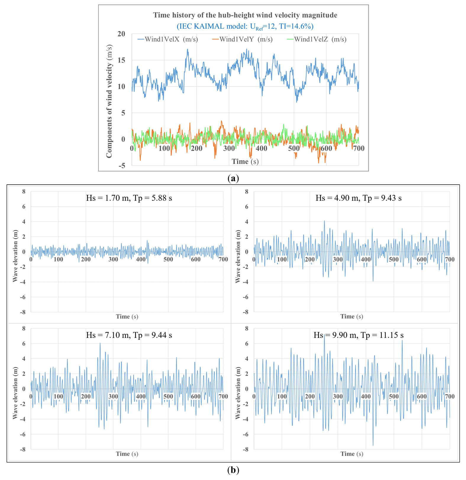 |
Figure 6. Illustration of external environmental conditions: (a) Wind condition; (b) Wave condition.
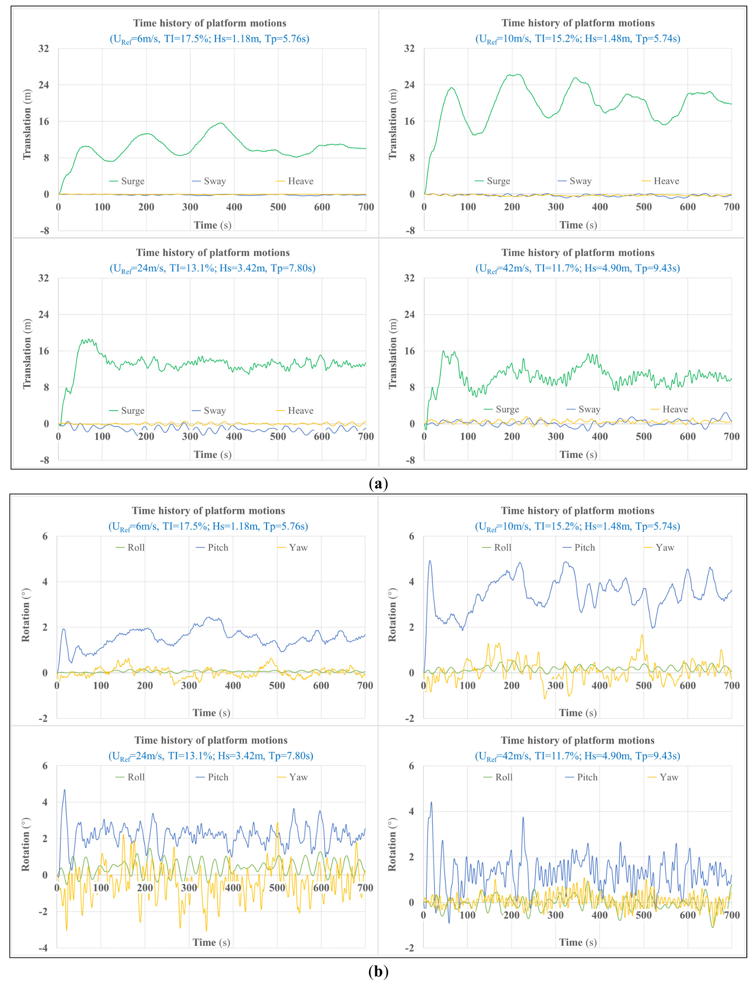
As illustrated in Figure 7, the floating platform motions are described by 6 DOFs: surge, sway, heave, pitch, roll, and yaw. Obviously, surge and pitch are dominant in platform translations and rotations, respectively, since large thrust forces and wind heeling moments act in their respective directions. Notably, the increase in significant wave height and peak-spectral period will cause significant oscillations in the platform motions in the direction of the incident waves.
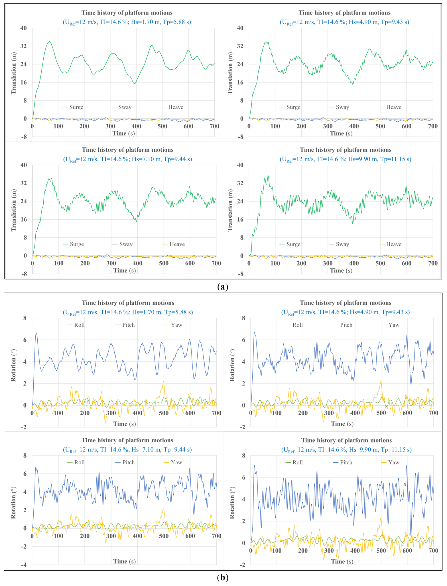
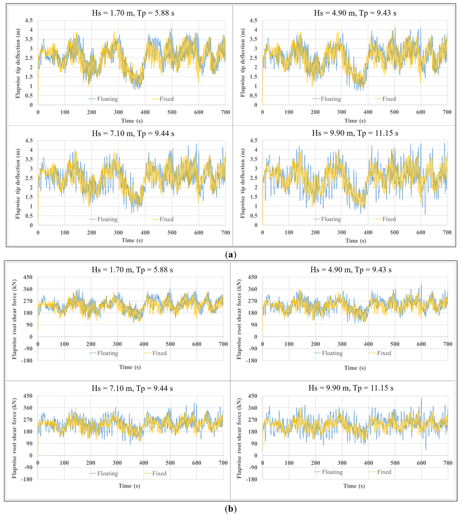
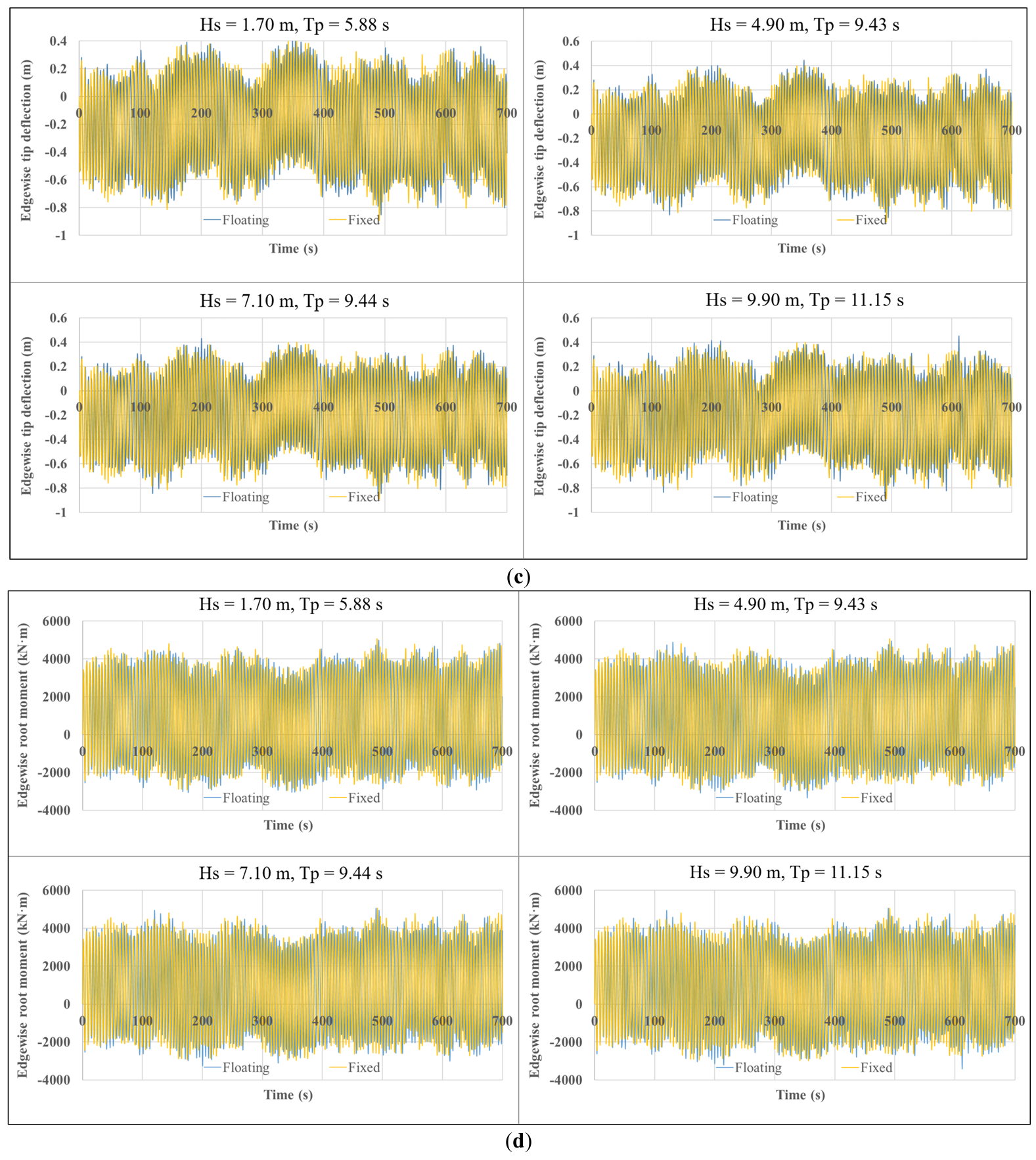
Figure 8 compares the effects of the four wave conditions on blade dynamic responses. Waves significantly influence the blade loads and motions under the same wind conditions. Specifically, as the significant wave height and peak-spectral period of incident waves increase, the flapwise, torsional, and axial peak responses of FOWTs increase significantly. For instance, when Hs rises from 1.70 m to 9.90 m, the difference in blade-tip flap between fixed-bottom and floating platforms increases from 0.104 m to 0.363 m (a 249% increase), the difference in root flapwise moment increases from 528.1 kN·m to 1817.4 kN·m (an increase of 244%), and the difference in root pitching moment increases from 5.02 kN·m to 18.73 kN·m (an increase of 273%). However, edgewise direction differences are insignificant (the peak value of edgewise blade-tip deflection only increases from 0.040 m to 0.046 m with the increasing wave height). These comparisons highlight significant amplification of blade root loads by wave-induced platform motions. Conversely, edgewise response differences are insignificant, likely due to higher structural stiffness in that direction or weaker coupling between aerodynamic excitations and platform motions.
 |
 |
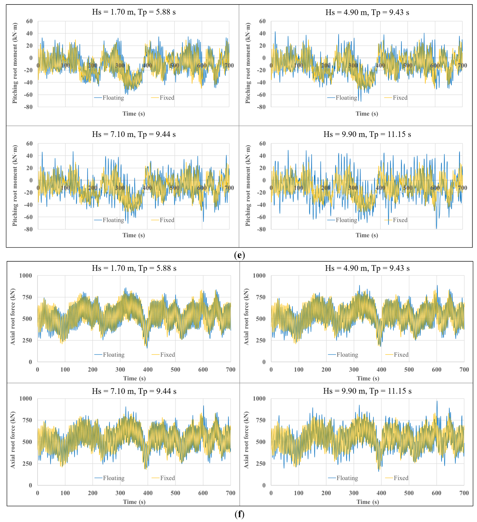 |
Figure 8. Blade dynamic responses under different wave conditions (LCs 3–6): (a) Flapwise tip deflection; (b) Flapwise shear force at the blade root; (c) Edgewise deflection at the blade tip; (d) Edgewise moment at the blade root; (e) Pitching moment at the blade root; (f) Axial tension at the blade root.
3.3.2. Coupled Effect of Wind and Wave
Except for load cases 3–6, the other load cases shown in Table 2 represent a range of wind and wind-induced wave conditions. Figure 9 illustrates the coupled effect of wind and wave on platform motions. By combining Figure 7 and Figure 9, it can be found that the greatest platform motions (the maximum values of the maximum dynamic response) are driven by simulations involving sustained near rated wind speed, because the thrust forces and wind heeling moments are typically the highest at rated wind speed.
Comparing the responses of blades on fixed-bottom and floating systems, as shown in Figure 10, enables quantification of the impact of the dynamic coupling between the turbine and floating platform in the presence of combined wind and wave loading. From Figure 10, it can be observed that the differences in peak dynamic responses between the fixed-bottom and floating systems under wind and wind-induced wave conditions are not as pronounced as those under varying wave-only conditions (Figure 8), and no uniform trend is evident. For one thing, in some cases, the comparison shows that the floating wind turbine exhibits a larger peak magnitude of blade responses (such as flapwise blade-root shear force during power production and most investigated responses during parking) compared to the fixed-bottom system. This may be caused by dynamic rotor motions upwind-downwind driven by platform surge and pitch motions—motions that alter the relative wind velocity at the rotor. For another, some surge motions result in a decrease in the relative wind speed seen at the blades, thus reducing the load. By combining Figure 8 and Figure 10, it is further noted that the peak responses of wind turbine blades mounted on the spar-type platform are more affected by waves than by wind.
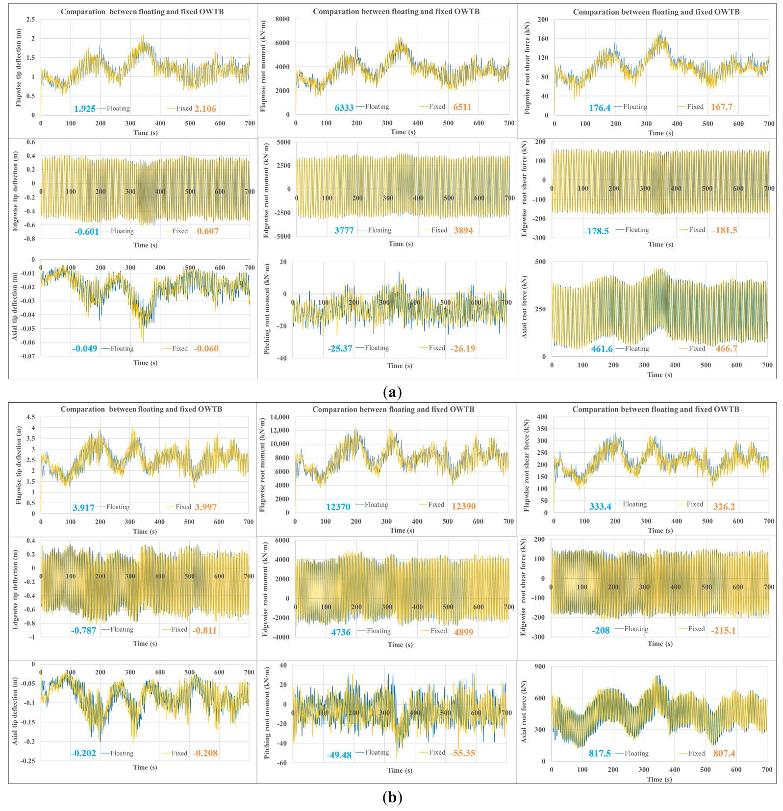
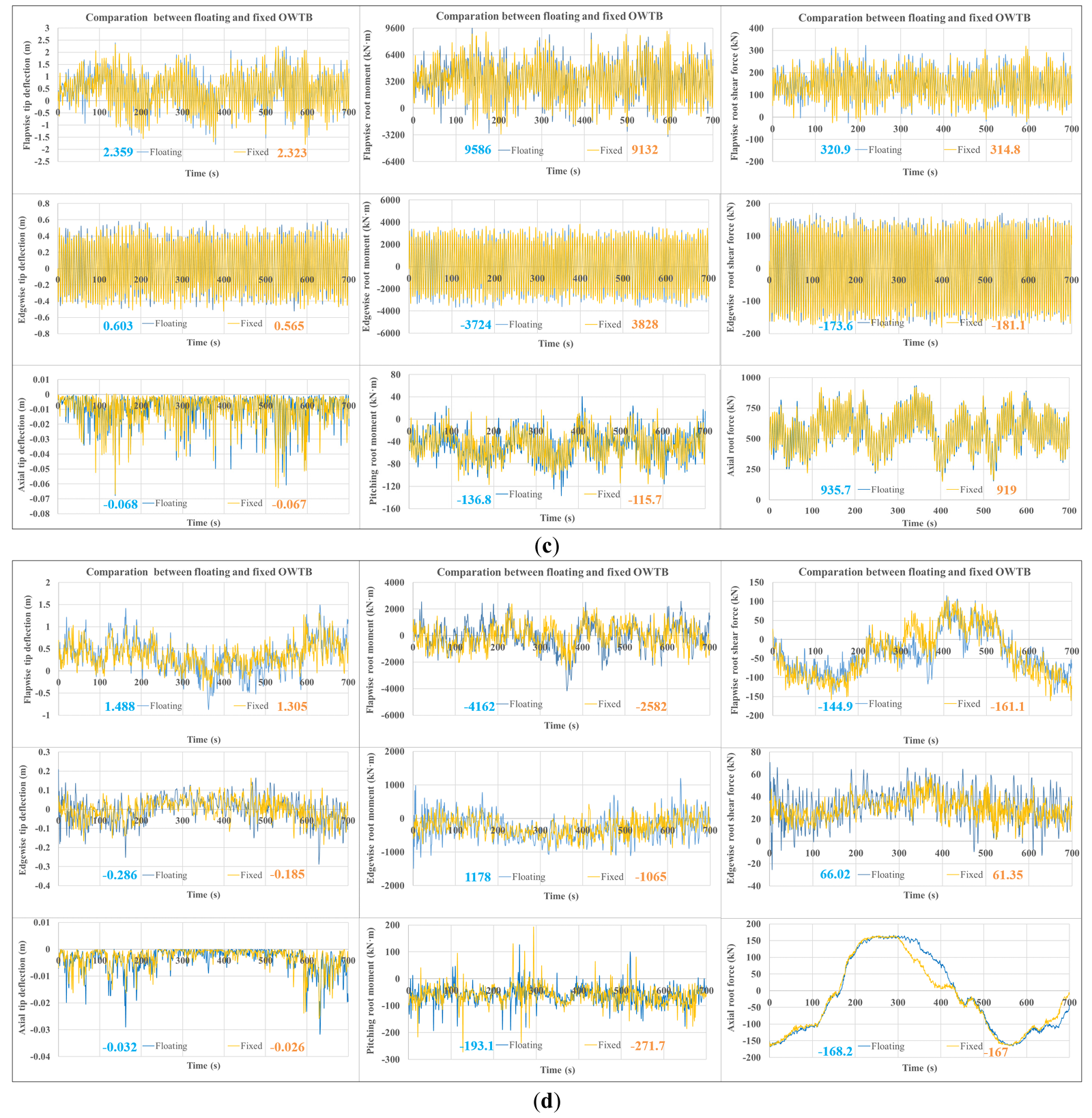
Figure 10. Coupled effect of wind and wave on blade dynamic responses (with extreme values marked): (a) LC 1; (b) LC 2; (c) LC 7; (d) LC 8.
3.4. Outlook for Future Research
While this study elucidates key coupling phenomena, several avenues warrant further investigation to enhance the fidelity and applicability of the findings. Future work should employ higher-fidelity structural dynamics methods, such as the geometrically exact beam theory implemented in BeamDyn or even 3D finite element models, to more accurately capture complex blade deformations and composite coupling effects. Notably, the OpenFAST BeamDyn module (based on geometrically exact beam theory and Legendre spectral finite element) that includes the DOFs bending, torsion, shear, and extension, with composite coupling terms, can be used to replace the ElastoDyn module for improving calculation accuracy, as discussed in [14]. Additionally, a broader range of environmental conditions must be explored, most notably the misalignment between wind and wave directions, which is common in real offshore sites and can drastically alter load patterns. The analysis should also be extended to larger, modern FOWTs (e.g., 15+ MW) to ensure relevance to current industry trends. Finally, to robustly address fatigue life prediction, longer simulation times and detailed spectral analysis of the response time series are essential for a statistically significant assessment of the long-term load cycles experienced by the composite laminate layers within the blade structure.
4. Conclusions
For obtaining a better understanding of how blade response differs between floating turbines and fixed-bottom turbines, in this work, aero-hydro-servo-elastic simulations of a 5-MW spar-type FOWT with floating and fixed-bottom platforms (rigid and flexible tower bases) are conducted under a wide range of wave conditions, as well as coupled wind and wave conditions. The effects of platform motions on the dynamic responses of floating offshore wind turbine blades are preliminarily investigated, and the following observations are summarized.
-
-
Quantitative comparison of the differences in mode shapes of support structures caused by different platform types shows that floating platform support structures have higher natural frequencies. The first-order natural frequency of the floating tower is approximately 29% higher than that of the fixed-bottom tower, with significant differences in mode shapes; the differences in second-order modal characteristics are smaller, and the difference in natural frequencies does not exceed 3%.
-
-
The increases in significant wave height (Hs) and corresponding peak-spectral period will cause significant oscillations in the platform motions in the direction of the incident waves. The higher the Hs, the greater the flapwise and torsional peak responses of the blades compared to those of fixed-bottom ones. When Hs is 1.70 m, the peak values of blade-tip flap deflection, root flapwise bending moment, and root torsional moment for FOWT blades are 0.104 m, 528.1 kN·m, and 5.02 kN·m higher than those of fixed-bottom platforms, respectively. When Hs reaches 9.9 m, the peak values of blade-tip flap deflection, root flapwise bending moment, and root torsional moment of FOWT blades are 0.363 m, 1817.4 kN·m, and 18.73 kN·m higher than those of fixed-bottom platforms, respectively. In addition, platform motion has a negligible effect on blade edgewise response, the difference in peak blade-tip edgewise deflection is less than 0.05 m. This indicates that when the wind direction angle is 0° and wind, waves, and currents are in the same direction, platform motion has a significant impact on the flapwise and torsional responses of blades, which should therefore be a key consideration in blade design.
-
-
The platform motions can both increase and mitigate the peak values of blade-tip motions and the blade-root structural loads. The blade responses are more sensitive to the wave condition, while the magnitude of platform motions is more sensitive to the wind condition. The corresponding mechanism requires further comprehensive and thorough investigation.
For future research to further evaluate this issue, the blade structure dynamics should be calculated more accurately using a method of higher fidelity, more additional environmental conditions (such as the misalignment of the wave and wind) and larger FOWTs representing current practice need to be examined in detail, especially for the ultimate strength and fatigue failure of various composite layers used in the blade laminate. Moreover, longer simulation times and spectrum assessment of the time series should be performed.
Supplementary Materials
The following supporting information can be found at: https://www.sciepublish.com/article/pii/764. The simulation codes and model data for the offshore wind turbine system in this work are open-source and can be found at https://github.com/OpenFAST/openfast (accessed on 13 November 2025, wind turbine simulation tool: OpenFAST v3.2.1), https://github.com/NREL/ROSCO (accessed on 13 November 2025, NREL’s Reference OpenSource Controller: ROSCO) and https://github.com/OpenFAST/r-test (accessed on 13 November 2025, Test 24: 5MW_OC3Spar_DLL_WTurb_WavesIrr). Moreover, data of the OpenFAST model and simulation details (taking the environmental setting of Load Case 3 as an example) involved in this manuscript are publicly available at https://git.zju.edu.cn/12112050/mer_supplementary-materials (accessed on 13 November 2025), so as to enable interested readers to reproduce the findings and conduct further innovative research.
Author Contributions
Conceptualization, B.W.; Methodology, B.W.; Software, B.W. and L.T.; Validation, B.W., Y.C. and J.Z.; Formal Analysis, Y.C. and L.T.; Investigation, B.W.; Resources, B.W.; Data Curation, H.Z. and Y.C.; Writing—Original Draft Preparation, B.W.; Writing—Review & Editing, B.W. and J.Z.; Visualization, J.Z. and H.Z.; Supervision, B.W.; Project Administration, B.W.; Funding Acquisition, B.W.
Ethics Statement
Not applicable.
Informed Consent Statement
Not applicable.
Data Availability Statement
Data will be made available on request.
Funding
Baoxuan Wang would like to acknowledge the fund from the Interdisciplinary Student Training Platform for Marine areas at Zhejiang University. Jianwei Zhang would like to acknowledge the Key Program of the Natural Science Foundation of Zhejiang Province (No. LZ24E070001).
Declaration of Competing Interest
The authors declare that they have no known competing financial interests or personal relationships that could have appeared to influence the work reported in this paper.
References
- Jonkman J, Musial W. Offshore Code Comparison Collaboration (OC3) for IEA Wind Task 23 Offshore Wind Technology and Deployment; No. NREL/TP-5000-48191; National Renewable Energy Laboratory: Golden, CO, USA, 2010. [Google Scholar]
- IEC 61400-3-1:2019; Wind Energy Generation Systems—Part 3-1: Design Requirements for Fixed Offshore Wind Turbines. International Electrotechnical Commission: Geneva, Switzerland, 2019. [Google Scholar]
- Wang B, Liang X, Zhang J, Rui S, Zha X, Wang S, et al. A Detailed Analysis Framework of Fully Coupled Dynamic Responses for Offshore Wind Turbine Blade. Int. Conf. Offshore Mech. Arct. Eng. 2023, 86908, V008T09A045. doi:10.1115/omae2023-104430. [Google Scholar]
- IEC 61400-3-2:2025; Wind Energy Generation Systems—Part 3-2: Design Requirements for Floating Offshore Wind Turbines. International Electrotechnical Commission: Geneva, Switzerland, 2025. [Google Scholar]
- Li Y, Li G, Zhu Q, Cui Y, Feng Y, Su O, et al. Effects of mooring line fracture on 15 MW floating offshore wind turbine under different operation strategies. Eng. Fail. Anal. 2025, 179, 109754. doi:10.1016/j.engfailanal.2025.109754. [Google Scholar]
- Wang B, Liang X, Jiang X. Experimental and Numerical Investigation on the Dynamic Response of Platform for a Spar-Type Floating Wind Turbine Under Aerodynamic and Hydrodynamic Forces. Int. Conf. Offshore Mech. Arct. Eng. 2022, 85932, V008T09A062. doi:10.1115/OMAE2022-81290. [Google Scholar]
- Johlas HM, Martínez‐Tossas LA, Churchfield MJ, Lackner MA, Schmidt DP. Floating platform effects on power generation in spar and semisubmersible wind turbines. Wind. Energy 2021, 24, 901–916. doi:10.1002/we.2608. [Google Scholar]
- Zavvar E, Rosa-Santos P, Taveira-Pinto F, Ghafoori E. Lifetime extension of offshore support structures of wind turbines: A review. Renew. Sustain. Energy Rev. 2025, 217, 115788. doi:10.1016/j.rser.2025.115788. [Google Scholar]
- Zavvar E, Rosa-Santos P, Ghafoori E, Taveira-Pinto F. Analysis of tubular joints in marine structures: A comprehensive review. Mar. Struct. 2025, 99, 103702. doi:10.1016/j.marstruc.2024.103702. [Google Scholar]
- Liu Y, Li S, Yi Q, Chen D. Developments in semi-submersible floating foundations supporting wind turbines: A comprehensive review. Renew. Sustain. Energy Rev. 2016, 60, 433–449. doi:10.1016/j.rser.2016.01.109. [Google Scholar]
- Igwemezie V, Mehmanparast A, Kolios A. Current trend in offshore wind energy sector and material requirements for fatigue resistance improvement in large wind turbine support structures—A review. Renew. Sustain. Energy Rev. 2019, 101, 181–196. doi:10.1016/j.rser.2018.11.002. [Google Scholar]
- Li Y, Li H, Wang B, Meng H, Su O, Tang Y. Effects of various freak waves on dynamic responses of a Spar-buoy floating offshore wind turbine. Ocean. Eng. 2024, 311, 118837. doi:10.1016/j.oceaneng.2024.118837. [Google Scholar]
- Nejad AR, Bachynski EE, Kvittem MI, Luan C, Gao Z, Moan T. Stochastic dynamic load effect and fatigue damage analysis of drivetrains in land-based and TLP, spar and semi-submersible floating wind turbines. Mar. Struct. 2015, 42, 137–153. doi:10.1016/j.marstruc.2015.03.006. [Google Scholar]
- IEC 61400-5:2020; Wind Energy Generation Systems—Part 5: Wind Turbine Blades. International Electrotechnical Commission: Geneva, Switzerland, 2025. [Google Scholar]
- Brøndsted P, Nijssen RPL, Goutianos S. Advances in Wind Turbine Blade Design and Materials, 2nd ed.; Woodhead Publishing Limited: Cambridge, UK, 2023. [Google Scholar]
- Wu S, Zhang H, Zhang L, Wang L, Sun X, Maeda T, et al. Multi-objective structural optimization of long flexible wind turbine blades for enhanced lightweight and reliability. Energy 2025, 336, 138487. doi:10.1016/j.energy.2025.138487. [Google Scholar]
- Papi F, Bianchini A. Technical challenges in floating offshore wind turbine upscaling: A critical analysis based on the NREL 5 MW and IEA 15 MW Reference Turbines. Renew. Sustain. Energy Rev. 2022, 162, 112489. doi:10.1016/j.rser.2022.112489. [Google Scholar]
- Robertson AN, Jonkman JM. Loads Analysis of Several Offshore Floating Wind Turbine Concepts. In Proceedings of the ISOPE 2011, 21st International Offshore and Polar Engineering Conference, Maui, HI, USA, 19–24 June 2011; International Society of Offshore and Polar Engineers: Mountain View, CA, USA, 2011; pp. 443–450. [Google Scholar]
- Jonkman JM, Matha D. Dynamics of offshore floating wind turbines—Analysis of three concepts. Wind. Energy 2011, 14, 557–569. doi:10.1002/we.442. [Google Scholar]
- OpenFAST Documentation. Release v3.2.1. National Renewable Energy Laboratory. 2022. Available online: https://github.com/OpenFAST/openfast (accessed on 13 November 2025). [Google Scholar]
- Jonkman BJ. TurbSim User’s Guide: Version 1.50; Technical Report No. NREL/TP-500-46198; National Renewable Energy Laboratory: Golden, CO, USA, 2009. [Google Scholar]
- Bir GS. User’s Guide to PreComp (Pre-Processor for Computing Composite Blade Properties); Technical Report NREL/TP500-38929; National Renewable Energy Laboratory (NREL): Golden, CO, USA, 2006. [Google Scholar]
- ANSYS Inc: Release 19.0. Available online: https://ansyshelp.ansys.com/ (accessed on 13 November 2025). [Google Scholar]
- Bir G. User’s Guide to BModes (Software for Computing Rotating Beam-Coupled Modes); Tech. Rep. NREL/TP-500-39133; National Renewable Energy Laboratory (NREL): Golden, CO, USA, 2005. [Google Scholar]
- Bir G, Jonkman J. Modal Dynamics of Large Wind Turbines with Different Support Structures. In Proceedings of the ASME 2008 27th International Conference on Offshore Mechanics and Arctic Engineering, Estoril, Portugal, 15–20 June 2008; ASME: New York, NY, USA, 2008; pp. 669–679. [Google Scholar]
- Wang B, Wang L, Liang X, Sheng F, Zhang J, Hong Y, et al. 3D multiscale dynamic analysis of offshore wind turbine blade under fully coupled loads. Renew. Energy 2024, 223, 119985. doi:10.1016/j.renene.2024.119985. [Google Scholar]
- Jonkman J, Butterfield S, Musial W, Scott G. Definition of a 5-MW Reference Wind Turbine for Offshore System Development; Technical Report NREL/TP-500-38060; National Renewable Energy Laboratory: Golden, CO, USA, 2009. [Google Scholar]
- Resor BR. Definition of a 5MW/61.5 m Wind Turbine Blade Reference Model; Technical Report SAND2013-2569 2013; Sandia National Laboratories: Albuquerque, NM, USA, 2013. [Google Scholar]
- Jonkman J. Definition of the Floating System for Phase IV of OC3; Technical Report NREL/TP-500-47535; National Renewable Energy Laboratory: Golden, CO, USA, 2010. [Google Scholar]
- Fischer T, De Vries W, Schmidt B. UpWind Design Basis (WP4: Offshore Foundations and Support Structures), Project UpWind: Stuttgart, Germany, 2010. Available online: https://www.upwind.eu/images/wp4_designbasis.pdf (accessed on 13 November 2025). [Google Scholar]
- IEC 61400-1:2019; Wind Energy Generation Systems—Part 1: Design Requirements. International Electrotechnical Commission: Geneva, Switzerland, 2019. [Google Scholar]
- IEC 61400-3:2009; Wind Turbines—Part 3: Design Requirements for Offshore Wind Turbines. International Electrotechnical Commission (IEC): Geneva, Switzerland, 2009. [Google Scholar]
- Haid L, Stewart G, Jonkman J, Robertson A, Lackner M, Matha D. Simulation-Length Requirements in the Loads Analysis of Offshore Floating Wind Turbines. In Proceedings of the ASME 2013 32nd International Conference on Ocean, Offshore and Arctic Engineering, Nantes, France, 9–14 June 2013; ASME: New York, NY, USA, 2013; Volume 55423, p. V008T09A091. [Google Scholar]