Application of Blades Aerodynamic Optimization Design Platform Based on the Performance of Offshore Wind Turbines

Application of Blades Aerodynamic Optimization Design Platform Based on the Performance of Offshore Wind Turbines
Meng Gao 1 Ankang Sun 1 Yinan Zhang 2,* Huipeng You 1
Received: 21 September 2025 Revised: 23 October 2025 Accepted: 03 November 2025 Published: 06 November 2025

© 2025 The authors. This is an open access article under the Creative Commons Attribution 4.0 International License (https://creativecommons.org/licenses/by/4.0/).
1. Introduction
Offshore wind energy has emerged as a vital component of the global renewable energy transition [1,2,3]. With stronger and more consistent winds at sea compared to onshore locations, offshore wind farms can generate substantial electricity with high efficiency [4,5]. Over the past decade, technological advancements, policy support, and decreasing costs have accelerated the deployment of offshore wind projects worldwide. The offshore wind industry is rapidly advancing towards larger-scale projects to enhance efficiency, reduce costs, and maximize energy output [6,7,8]. One key trend is the deployment of massive wind turbines, with modern models exceeding 15–20 MW per unit, compared to the 3–6 MW turbines that were common a decade ago [9,10,11]. For instance, GE’s Haliade-X (14 MW) and MingYang’s MySE 16–260 (16 MW) demonstrate how increased rotor diameters (over 260 m) and taller towers capture stronger winds, thereby boosting capacity factors. Another major shift is the development of gigawatt-scale wind farms [12,13,14,15]. Projects like the UK’s Dogger Bank (3.6 GW) and China’s Guangdong complex (17 GW upon completion) highlight the shift towards clustered installations in high-wind zones. These mega-projects benefit from economies of scale, lowering installation and maintenance costs per MW.
The relentless pursuit of larger offshore wind turbines, with rotor diameters now exceeding 250 m and individual blades stretching beyond 120 m, has introduced unprecedented engineering complexities in blade design. As the industry pushes the boundaries of scale to enhance energy capture and reduce levelized costs, several critical technical challenges for the design of blades have emerged that demand innovative solutions. As blade length increases, the aerodynamic and structural loads they endure also rise significantly, imposing higher demands on blade design. How to maintain excellent aerodynamic performance under low load conditions has become a primary task in current high-power wind turbine blade design. However, improvements in wind turbine blade power generation efficiency inevitably come with higher loads. Therefore, in iterative blade design, we cannot solely pursue optimization goals focused on high power generation efficiency.
Currently, aerodynamic optimization of wind turbine blades primarily involves parametric modeling of airfoil profiles [16,17,18], combined with various optimization algorithms and CFD simulations to achieve target improvements [19,20,21]. This approach enhances power generation performance by increasing the airfoil’s lift-to-drag ratio, thereby improving blade efficiency through the use of optimized airfoil shapes. In comprehensive optimization methods based on three-dimensional blade geometry [22,23,24,25,26], key parameters such as chord length and twist distribution are optimized, with design objectives including power generation efficiency [27], aerodynamic noise [28], and weight reduction. However, these conventional methods predominantly focus on the blade’s aerodynamic performance while largely neglecting design requirements for turbine safety and stability. When considering overall power generation efficiency, multi-objective optimization algorithms are employed for aerodynamic blade design, but convergence issues frequently occur during the optimization process, requiring extended iteration cycles to ensure solution validity. Consequently, traditional blade aerodynamic optimization methods exhibit significant limitations in wind turbine system design.
In the blade design process, simultaneously achieving load reduction while maintaining excellent aerodynamic performance can effectively prevent issues of overloading or low power generation efficiency. Different from conventional blade optimization design methods, the approach developed in this paper considers both the power generation performance and the load level of the blade as optimization objectives. While maintaining high power generation efficiency, it also requires the blade to have low root loads. Additionally, the method in this study can rapidly generate multiple aerodynamic blade shape schemes that meet the design requirements, unlike traditional design methods that rely on comparative analysis of a limited number of design options. Such optimized blades demonstrate superior turbine compatibility and enhanced market competitiveness. This study conducts blade redesign by balancing power generation requirements with load safety considerations, developing an aerodynamics optimization method based on overall turbine performance. By optimizing the blade’s aerodynamic shape to match both power output and load level requirements, the designed blades achieve better compatibility with wind turbines and greater market competitiveness. This aerodynamic optimization approach effectively enhances both the power generation performance and operational stability of wind turbines, offering a safe and reliable solution for designing large-capacity offshore wind turbine blades. This paper begins by presenting the capabilities of the blade aerodynamic design platform, including its computational methods, boundary condition settings, and data processing workflow. Subsequently, based on the development requirements for an 8.5 MW wind turbine, an aerodynamic profile scheme that meets the design specifications is obtained. Finally, the compliant aerodynamic profiles are evaluated and screened by balancing power generation performance against root load levels to determine the final blade aerodynamic layout.
2. Descriptions of the Wind Turbine Blade Aerodynamic Optimization Design Platform
The blade optimization design platform provides aerodynamic profile optimization algorithms. As shown in Figure 1, it generates high-performance blade geometries based on boundary conditions while simultaneously evaluating aerodynamic performance, including power curves and tip-speed ratios. Furthermore, the optimization platform can obtain blade root loads, stall characteristics, as well as complete turbine parameters such as rotor speed, thrust, power output, and annual full-load hours. This enables the development of aerodynamically optimized blade configurations with superior turbine compatibility under various environmental conditions. The blade optimization design platform significantly enhances aerodynamic design efficiency, reduces labor costs, decreases error rates, and improves production quality and reliability by applying automated design principles. The design platform’s core functionalities include:
-
-
Batch comparison of GH-Bladed data package files
-
-
Batch calculation of blade performance
-
-
Environmental adaptability assessment
-
-
Aerodynamic profile design
-
-
Generation of structural design input parameters
By implementing principles of operational simplification, reliability enhancement, and flexible scalability, the blade design platform can better meet user requirements and adapt to future developments in the wind energy industry.
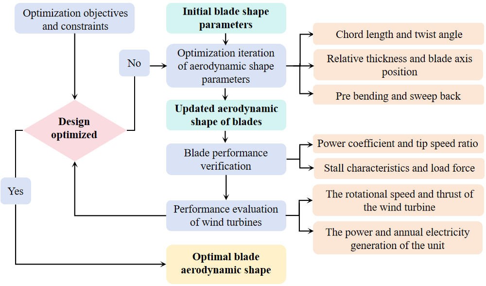
As shown in Figure 2, the optimization design platform utilizes the main program to perform iterative optimization based on the initial blade input file, ultimately outputting the target blade profile parameters. Simultaneously, it can automatically generate the necessary files and data for structural design, streamlining the structural design process and enabling seamless integration with blade structural design software such as FOCUS6 and CATIA.2020. The optimization design platform is developed using MATLAB.2024 programming. Taking 500 blade profile output samples as an example, the platform completes the iterative optimization and outputs the blade profile in 1.5 min, while generating the blade performance and complete turbine parameter results in approximately 5.0 min, demonstrating high optimization efficiency. Additionally, it synchronously produces comparative result curves.
The Input directory contains all required input files for computation, including:
-
-
Standard airfoil coordinate point clouds
-
-
Initial blade aerodynamic and structural parameters
-
-
Wind turbine model data
-
-
BLADED initial blade data packages
-
-
Stall characteristic evaluation data files
The main.m file contains execution scripts for multiple design functions:
-
-
Blade profile conversion
-
-
Blade data comparison
-
-
Batch execution of BLADED solver
-
-
Environmental adaptability assessment
-
-
Blade optimization design
The Output directory stores all generated results:
-
-
3D blade geometry models
-
-
FOCUS models
-
-
Computational evaluation results
-
-
Stall characteristic evaluation results
-
-
Optimized blade designs
-
-
Comparative plots and process log files

3. Results and Discussion
3.1. Descriptions of the Wind Turbine
This study utilizes a self-developed high-power wind turbine platform, that adopts variable speed, pitch control, and yaw regulation strategies. Table 1 presents the operational parameters of this turbine. Based on an 8.5 MW wind turbine, a GH-Bladed platform computational model is constructed to evaluate the blade’s power generation performance and load levels. During the design process, wind turbine blades must meet the requirements for both power generation efficiency and load capacity to align with the development targets of the wind turbine. The performance indicators required for the design of this 8.5 MW wind turbine blade are listed in Table 2.
Table 1. Geometrical and operational characteristics of a wind turbine.
|
Parameters |
Design Value |
|---|---|
|
Wind regime |
IEC ⅢC |
|
Power generation |
8.5 MW |
|
Rotor orientation |
Upwind |
|
Rotation |
Clockwise |
|
Number of blades |
3 |
|
Cut-in wind speed |
3 m/s |
|
Cut-out wind speed |
22 m/s |
|
Rated wind speed |
11 m/s |
|
Rotor diameter |
200 m |
|
Hub height |
140 m |
|
Lifetime |
20 years |
Table 2. Development requirements for wind turbine blade.
|
Blade Design Objectives |
Design Value |
|---|---|
|
Blade power coefficient CP |
≥0.45 |
|
Load at blade root |
≤2.6 × 10⁷ kNm |
|
Annual hours of full power generation (rated wind speed) |
≥5000 h |
3.2. Optimization of the Aerodynamic Shape of Wind Turbine Blades
The blade redesign was completed based on the aerodynamic optimization design platform developed in this study, resulting in optimized adjustments to power generation efficiency and load stability. The blade shape optimization program simultaneously iteratively optimizes the chord length, twist angle, relative thickness, blade central axis, and sweep/dihedral deformation. During the iteration process, eight optimization control points were selected on the shape layout curve, with each control point generating a new shape layout positioning point through random sampling. Subsequently, multi-order spline curves were used to fit these positioning points, generating a new aerodynamic shape layout curve. To ensure optimization stability, the allowable variation range of the shape curve was constrained to within 5%.
The number of shape samples per optimization iteration was set to 500, with the results for chord length, relative thickness, and twist angle shown in Figure 3. To efficiently obtain solutions that meet the design requirements, constraint boundary conditions were defined for the blade power coefficient (Cp) and tip-speed ratio (λ), requiring 0.45 ≤ Cpmax ≤ 0.47 and 11 ≤ λ < 12. As illustrated in Figure 4, the solution marked by a red star represents the blade shape layout that satisfies the optimization objectives. The power coefficients corresponding to the above blade shapes and the overall power generation of the wind turbine are shown in Figure 5 and Figure 6. Different blades exhibit distinct power curve distribution patterns. The maximum power coefficient for each blade type is around 0.46, occurring within a tip-speed ratio range of 10 to 12.5. Meanwhile, when the wind turbine reaches full power, the corresponding rated wind speeds for different blade shapes range between 10.4 and 12 m/s. As illustrated in Figure 7 and Figure 8, by extracting the turbine’s operational data under rated conditions, it can be observed that as the rated wind speed of the turbine increases, the corresponding power coefficient of the blade under rated conditions gradually decreases, while the resulting root loads show a declining trend. It can also be understood that the higher the rated wind speed of the wind turbine, the lower the ultimate load of the blades at the rated wind speed.
A comparison of the computational results reveals that increasing the blade chord length and twist angle effectively enhances the blade solidity and aerodynamic capture capability. This enables the blades to capture sufficient aerodynamic torque to reach the rated power at lower wind speeds, consequently reducing the rated wind speed. With increased solidity, adequate torque can be generated at lower rotational speeds, whereas excessively high speeds would instead increase drag losses. To achieve the rated power at lower wind speeds, the control system opts to reduce the rotational speed to align with the new, lower tip-speed ratio, thereby simultaneously achieving a reduction in both the rated rotational speed and the design tip-speed ratio. Aerodynamically superior profiles generally improve the maximum power coefficient Cpmax, enhancing wind energy conversion efficiency across all wind speed ranges before reaching the rated power. This is particularly evident in the frequently occurring low-wind-speed periods, significantly boosting the total annual energy production.

Figure 3. Result of the shape distribution of the iterated sample. (a) Chord length; (b) Relative thickness; (c) Twist angle.


Figure 8. Blade power coefficient with different root load.
Correspondingly, based on the performance indicators required for blade design (Table 2), three optimal solutions were selected from the shape layouts that met the optimization criteria: Blades #172, #397, and #436. Their corresponding shape results are presented in Figure 9. Among them, the 436# blade has a relatively smaller overall chord length distribution, while the 172# and 397# blades exhibit higher chord length values from the root to the mid-span. A larger chord length helps reduce the risk of stalling during blade operation [29,30,31,32,33]. All three blades have similar relative thickness levels near the root. However, the 397# blade has a higher relative thickness, whereas the 172# blade has a smaller relative thickness near the tip. A thinner blade profile improves aerodynamic performance, thereby enhancing power generation efficiency [33,34,35,36]. Additionally, the 397# blade has a smaller twist angle distribution in the mid-span, while the 172# and 436# blades have smaller twist angles near the 10 m tip region. The twist angle distribution influences whether the blade operates at the designed angle of attack of the airfoil, thereby significantly affecting the blade’s power generation performance [37,38].

Figure 9. Aerodynamic shape of the optimized blade. (a) Chord length; (b) Relative thickness; (c) Twist angle.
3.3. Analysis of Aerodynamic Performance of Blades
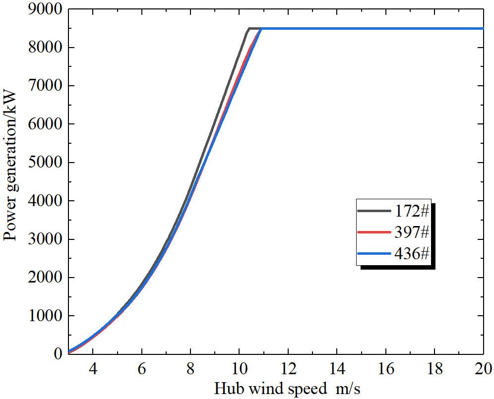
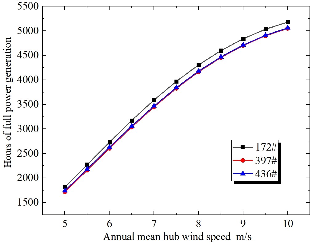
As shown in Figure 10, the power generation efficiency of the three blade designs shows no significant difference, with their maximum power coefficients all around 0.466 at a tip-speed ratio of 10.5. However, the 172# blade demonstrates higher efficiency under both high and low wind speeds. As shown in the shape results in Figure 9, the 172# blade, with its larger chord length and thinner profile, delivers superior aerodynamic performance. This enables it to achieve higher power generation efficiency within the 5–11 m/s wind speed range. Its excellent efficiency allows the wind turbine to reach full power output at a lower rated wind speed of 10.4 m/s. In contrast, the 397# and 436# blades, due to their relatively lower efficiency, require a higher rated wind speed of 10.9 m/s, as illustrated in Figure 11 and Figure 12. The 397# blade benefits from its larger chord length and lower twist angle, which contribute to improved aerodynamic performance. However, its higher relative thickness compared to the 436# blade results in no significant difference in power generation performance between the two. According to the calculations in Figure 13, when a wind turbine is equipped with the high-performance 172# blade, its annual full-power generation hours exceed those of turbines using the 397# and 436# blades.


3.4. Analysis of Load Level of Blades
For offshore fixed wind turbines, the primary source of blade loading originates from incoming wind flow, with aerodynamic forces constituting the dominant loading component. While wave-induced inertial forces are largely attenuated before reaching the rotor system, they nevertheless contribute to transient load variations that can affect operational stability [39,40]. Consequently, wave-induced disturbances have been incorporated in the stability analysis of turbine performance. The numerical simulations employ the JONSWAP/Pierson-Moskowitz wave spectrum with a significant wave height of 1.5 m within the GH-Bladed computational platform. The corresponding wave spectral characteristics are detailed in Table 3. The superior aerodynamic performance of the blade leads to higher wind energy utilization, which inevitably subjects the blade to increased aerodynamic forces and consequently results in higher root loads. As illustrated in Figure 14 and Figure 15, the 172# blade exhibits the highest thrust and root loads under rated wind speed conditions. Similarly, owing to its larger chord length and reduced twist angle, the 397# blade experiences greater thrust and root loads compared to the 436# blade at rated wind speed. Analysis of the blade loading results reveals that the primary geometric factors influencing load magnitude are chord length and twist angle distribution, whereas variations in relative thickness do not play a decisive role.
Table 3. Wave model.
|
Wave Characteristics |
JONSWAP/Pierson-Moskowitz Spectrum |
|---|---|
|
Peak spectral period |
6 s |
|
Significant wave height |
1.5 m |
|
Peakedness(1 = Pierson-Moskowitz) |
1 |


Based on the instantaneous inflow wind speeds at different rated wind speeds in Figure 16, the performance parameters of wind turbines equipped with different blades were obtained. The 172# blade has a rated wind speed of 10.4 m/s, while the 397# and 436# blades correspond to a higher rated wind speed of 10.9 m/s. Consequently, the instantaneous inflow wind speed for the 172# blade is significantly lower than that of the other two blades. As shown in Figure 17, the fluctuation trend of turbine power generation closely follows the variation in inflow wind speed. Power output increases with rising wind speed. Although the 172# blade exhibits the best power generation performance, its lower rated wind speed results in consistently lower total power output compared to turbines equipped with the other blades. Analysis of Figure 17 and Figure 18 reveals that when the inflow wind speed exceeds 12 m/s, the 397# blade experiences destructive root load fluctuations, exhibiting a load divergence state. Simultaneously, the power output of the turbine equipped with this blade shows severe instability. By extracting the inflow angle of attack from Figure 19, it is found that the primary cause of load divergence in the 397# blade is the high angle of attack at the mid-span under rated wind speed conditions, leading to deep stall and consequently excessive load fluctuations. This also severely impacts the turbine’s power generation. As illustrated in Figure 9c, this phenomenon occurs because the 397# blade has a low twist angle and high thickness at the mid-span. The #436 blade has a relatively low twist angle near the tip, which increases the inflow angle of attack in that region and significantly raises the likelihood of stall. Therefore, despite its aerodynamic advantage from a larger chord length, the insufficient twist angle and excessive thickness are the primary triggers for stall-induced instability during operation.
Through further processing of the transient load data for the 172# and 436# blades, the results shown in Figure 20 were obtained. The transient load stability of these two blade designs shows no significant difference, indicating comparable fatigue load characteristics between them. Based on a comprehensive analysis of aerodynamic performance and overall turbine efficiency, our developed blade optimization platform enables rapid iterative design refinement, from which three blade configurations meeting the optimization objectives were identified. Among these, the 397# blade exhibits notable stall risks, making it an unsuitable candidate for the optimal design. While the 172# and 436# blades demonstrate equivalent power generation performance, the 172# design carries higher ultimate load levels. In contrast, the 436# blade maintains excellent aerodynamic efficiency while achieving lower ultimate loads, effectively avoiding both overload risks and power generation deficiencies. The key aerodynamic parameters of the optimized 436# blade are detailed in Table 4. This aerodynamic optimization design method successfully achieves rapid iterative optimization of blade geometry, striking an optimal balance between load mitigation and power generation efficiency. The resulting blades exhibit enhanced turbine compatibility and superior market competitiveness, demonstrating the platform’s capability to produce designs that neither excessively compromise energy output nor structural reliability.
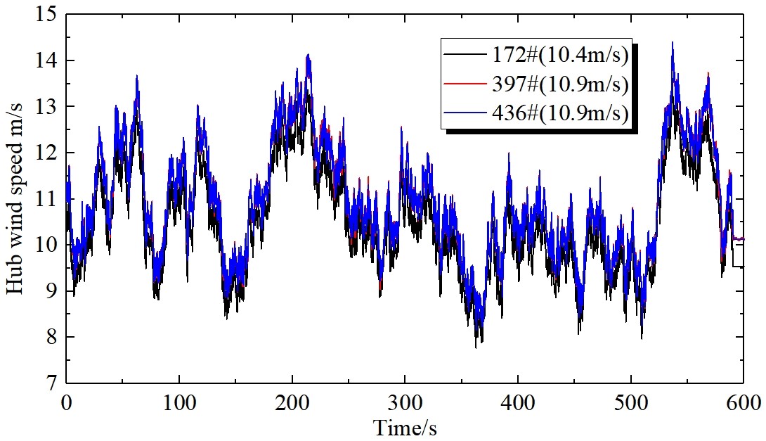


Table 4. Design parameters and performance indicators of blades.
|
Parameters |
436# Blade |
|---|---|
|
Length |
98 m |
|
Diameter of blade root |
3200 mm |
|
Maximum chord length |
4.141 m |
|
Pre bending of the blade tip |
4.8 m |
|
Twist angle of the blade root |
15° |
|
First order flapwise frequency |
0.2877 Hz |
|
First-order edgewise frequency |
0.5113 Hz |
|
First-order torsional frequency |
5.6189 Hz |
|
Steady maximum power coefficient |
0.4679 |
|
Weight |
25.8 t |
4. Conclusions
In order to improve the power generation efficiency of wind turbines while ensuring operational stability, the development of high-efficiency, low-load blades has become a core objective in the design of large-scale wind turbine blades. This paper presents a blade aerodynamic optimization design platform based on the performance of a wind turbine, which rapidly iterates to obtain blade aerodynamic profiles that meet the requirements of turbine development, balancing power output and load levels. The main conclusions of the study are as follows:
- (1)
- The blade aerodynamic optimization design platform significantly enhances design efficiency and reliability through the application of automated design principles. This platform enables batch performance calculations, environmental adaptability assessments, and aerodynamic profile optimization for wind turbine blades. With advantages such as simplified operation, improved reliability, and flexible scalability, the platform better meets the needs of designers and aligns with the evolving demands of the wind energy industry.
- (2)
- The aerodynamic profile of wind turbine blades has a significant impact on both power generation and load levels, necessitating simultaneous optimization of chord length, twist angle, and relative thickness. Among these, optimizing chord length and relative thickness distribution contribute notably to improving power performance and reducing loads. Additionally, the relative thickness and twist angle distribution are key parameters influencing stall characteristics during blade operation. Optimizing these parameters helps mitigate the risk of stalling.
- (3)
- Optimizing the twist angle distribution of the blade allows the local airfoil to operate closer to its optimal design angle of attack, thereby enhancing the blade’s aerodynamic performance. Blades with superior aerodynamic performance enable wind turbines to reach rated power output at lower inflow wind speeds. Moreover, excellent aerodynamic performance significantly increases the annual hours of rated power generation. However, such high aerodynamic performance is also a primary contributor to higher thrust and root loads on the blade. Additionally, a larger chord length distribution notably exacerbates blade loading.
- (4)
- Among the aerodynamic blade profiles meeting the wind turbine development requirements, the #397 blade exhibits severe stall issues at inflow wind speeds exceeding 12 m/s, which detrimentally affects both power generation and load stability. The #172 blade demonstrates the best aerodynamic performance, enabling the turbine to achieve rated power at an inflow speed of 10.4 m/s, with a maximum power coefficient (Cpmax) of 0.4695. However, under rated conditions, the #172 blade experiences an extreme load of 25,735.8 kNm, posing challenges to turbine safety. In contrast, while the #436 blade requires a slightly higher rated wind speed of 10.9 m/s, it exhibits significantly lower ultimate and fatigue loads. Furthermore, its annual rated power generation hours across varying wind speeds meet the turbine’s development requirements. Thus, the #436 blade demonstrates superior compatibility and matching performance with this 8.5 MW turbine.
5. Limitations and Future Research
Wind turbine blade design faces the challenge of complexity in multidisciplinary coupling and multi-objective trade-offs. This study primarily focuses on power generation efficiency and structural loads for the aerodynamic design of the blade, without comprehensively considering multiple objectives such as weight, noise, and cost. Single-discipline optimization struggles to achieve a globally optimal solution. Secondly, the optimization method employed in this research is based on fixed wind conditions and therefore fails to fully account for the complex turbulence and shear effects that occur in real wind farms. Future studies will integrate actual operational parameters of wind farms and leverage machine learning algorithms to achieve efficient and automated trade-offs among multiple objectives, including aerodynamics, structure, acoustics, and cost.
Statement of the Use of Generative AI and AI-Assisted Technologies in the Writing Process
During the preparation of this work the authors used DeepSeek in order to improve readability and language. After using this tool/service, the authors reviewed and edited the content as needed and take full responsibility for the content of the publication.
Acknowledgments
This work was supported by the development and research project of CRRC Shandong Wind Power Co., Ltd.
Author Contributions
Conceptualization, Y.Z.; Methodology, M.G.; Software, M.G.; Validation, A.S. and H.Y.; Formal Analysis, M.G. and A.S.; Investigation, Y.Z.; Data Curation, A.S. and M.G.; Writing—Original Draft Preparation, Y.Z.; Writing—Review & Editing, Y.Z.; Visualization, M.G.; Supervision, Y.Z.; Project Administration, Y.Z.
Ethics Statement
Not applicable for studies not involving humans or animals.
Informed Consent Statement
Not applicable for studies not involving humans.
Data Availability Statement
The data is publicly available and can be used with the author's approval.
Funding
This research received no external funding.
Declaration of Competing Interest
The authors declare that they have no known competing financial interests or personal relationships that could have appeared to influence the work reported in this paper.
References
-
Ma Y, Zhao R, Zhao W, Tai B, Dong G. Dynamic analysis to reduce the cost for fixed offshore wind energy turbines. Appl. Energy 2025, 378, 124804. doi:10.1016/j.apenergy.2024.124804. [Google Scholar]
-
Linnerud K, Dugstad A, Rygg BJ, Gilpin GS, Holden E. Energy crisis and social acceptance of offshore wind-A before-and-after analysis. Energy 2025, 325, 136049. doi:10.1016/j.energy.2025.136049. [Google Scholar]
-
Wang W, Wang B, Ke S, Zhang T, Ren H, He C, et al. Research on wind-wave induced dynamic responses and energy dissipation mechanism of the offshore new floating tube platform with flexible photovoltaic array. Ocean Eng. 2025, 318, 120077. doi:10.1016/j.oceaneng.2024.120077. [Google Scholar]
-
Pan W, Shittu E. Optimizing energy storage capacity for enhanced resilience: The case of offshore wind farms. Appl. Energy 2025, 378, 124718. doi:10.1016/j.apenergy.2024.124718. [Google Scholar]
-
Xi R. Dynamic analysis of 10 MW monopile supported offshore wind turbine based on fully coupled model. Ocean Eng. 2021, 234, 109346. doi:10.1016/j.oceaneng.2021.109346. [Google Scholar]
-
Zhang Y, Zhang Z, Zhong R, Yu J, Houssein EH, Zhao J, et al. Under complex wind scenarios: Considering large-scale wind turbines in wind farm layout optimization via self-adaptive optimal fractional-order guided differential evolution. Energy 2025, 323, 135866. doi:10.1016/j.energy.2025.135866. [Google Scholar]
-
Xie S, Li Y, Li Y, Kan Y. Preliminary study of the dynamics and environmental response of multiple floating offshore wind turbines on a single large-scale platform. Ocean Eng. 2025, 316, 120008. doi:10.1016/j.oceaneng.2024.120008. [Google Scholar]
-
Chen H, Sun Y, Cai Y, Charpentier J-F, Han J, Aït-Ahmed N, et al. Improved torque compensation control based-maximum power point tracking strategy for large scale floating offshore wind turbines. Ocean Eng. 2023, 273, 113974. doi:10.1016/j.oceaneng.2023.113974. [Google Scholar]
-
Koragappa P, Verdin PG. Design and optimisation of a 20 MW offshore wind turbine blade. Ocean Eng. 2024, 305, 117975. doi:10.1016/j.oceaneng.2024.117975. [Google Scholar]
-
Wang J, Ren Y, Shi W, Collu M, Venugopal V, Li X. Multi-objective optimization design for a 15 MW semisubmersible floating offshore wind turbine using evolutionary algorithm. Appl. Energy 2025, 377, 124533. doi:10.1016/j.apenergy.2024.124533. [Google Scholar]
-
Garrett E. Barter, Latha Sethuraman, Pietro Bortolotti, Jonathan Keller, David A. Torrey. Beyond 15 MW: A cost of energy perspective on the next generation of drivetrain technologies for offshore wind turbines. Appl. Energy 2023, 344, 121272. doi:10.1016/j.apenergy.2023.121272. [Google Scholar]
-
Fontenla-Carrera G, Pensado EA, Veiga-López F, González-Jorge H. Efficient offshore wind farm inspections using a support vessel and UAVs. Ocean Eng. 2025, 332, 121416. doi:10.1016/j.oceaneng.2025.121416. [Google Scholar]
-
Pryor SC, Barthelmie RJ. Wind shadows impact planning of large offshore wind farms. Appl. Energy 2024, 359, 122755. doi:10.1016/j.apenergy.2024.122755. [Google Scholar]
-
Thomas B, Costoya X, Decastro M, Carvalho D, Gómez-Gesteira M. Wake effect impact on the levelized cost of energy in large floating offshore wind farms: A case of study in the northwest of the Iberian Peninsula. Energy 2024, 304, 132159. doi:10.1016/j.energy.2024.132159. [Google Scholar]
-
Shao M, Mao Z, Sun J, Guan X, Shao Z, Tang T. Multi-scale offshore wind farm site selection decision framework based on GIS, MCDM and meta-heuristic algorithm. Ocean Eng. 2025, 316, 119921. doi:10.1016/j.oceaneng.2024.119921. [Google Scholar]
-
Bedon G, Paulsen US, Madsen HA, Belloni F, Castelli MR, Benini E. Computational assessment of the DeepWind aerodynamic performance with different blade and airfoil configurations. Appl. Energy 2017, 185, 1100–1108. doi:10.1016/j.apenergy.2015.10.038. [Google Scholar]
-
Zhang Y, Zhao M, Zhang M. Research on the aerodynamic performance of the wind turbine blades with leading-edge protuberances. Ocean Eng. 2023, 280, 114615. doi:10.1016/j.oceaneng.2023.114615. [Google Scholar]
-
Meng R, Chen L, Zhao R, Cai X, Xie N. Integrated design of aerodynamic and anti-flutter performance of offshore wind turbine airfoil based on full information cooperative game method. Ocean Eng. 2023, 281, 114967. doi:10.1016/j.oceaneng.2023.114967. [Google Scholar]
-
Chan CM, Bai HL, He DQ. Blade shape optimization of the Savonius wind turbine using a genetic algorithm. Appl. Energy 2018, 213, 148–157. doi:10.1016/j.apenergy.2018.01.029. [Google Scholar]
-
Zengin İ, Erdoğan B, Benim AC. CFD and Taguchi based optimization of air driven single stage partial admission axial turbine blade profiles. Energy 2024, 290, 130333. doi:10.1016/j.energy.2024.130333. [Google Scholar]
-
Fatahian E, Mishra R, Jackson FF, Fatahian H. Optimization and analysis of self-starting capabilities of vertical axis wind turbine pairs: A CFD-Taguchi approach. Ocean Eng. 2024, 302, 117614. doi:10.1016/j.oceaneng.2024.117614. [Google Scholar]
-
Zhang Y, Zhang C, You H, Liang K, Wei C, Sun A. Analysis of performance improvement methods for offshore wind turbine blades affected by leading edge erosion. Ocean Eng. 2024, 310, 118773. doi:10.1016/j.oceaneng.2024.118773. [Google Scholar]
-
Du Q, Yang L, Li L, Liu T, Zhang D, Xie Y. Aerodynamic design and optimization of blade end wall profile of turbomachinery based on series convolutional neural network. Energy 2022, 244, 122617. doi:10.1016/j.energy.2021.122617. [Google Scholar]
-
Nabhani A, Tousi NM, Coma M, Bugeda G, Bergada JM. Large-scale horizontal axis wind turbine aerodynamic efficiency optimization using active flow control and synthetic jets. Energy 2025, 319, 134940. doi:10.1016/j.energy.2025.134940. [Google Scholar]
-
Ma G, Liu L, Wang H, Zhang J, Sun K, Chen H. Reconstruction of scaled FOWT blades for achieving aerodynamic similarity with control strategy adjustment. Ocean Eng. 2025, 317, 120078. doi:10.1016/j.oceaneng.2024.120078. [Google Scholar]
-
Qian X, Zhang B, Gao Z, Wang T, Zhang L, Li Y. Flutter limit optimization of offshore wind turbine blades considering different control and structural parameters. Ocean Eng. 2024, 310, 118558. doi:10.1016/j.oceaneng.2024.118558. [Google Scholar]
-
Dai Y, Zhong L, Li B, Deng Z, Wang J, Zhao C. An analysis of the effects of a fused blade tip construction on a wind turbine's aerodynamic performance and wake flow characteristics was carried out. Ocean Eng. 2024, 313, 119464. doi:10.1016/j.oceaneng.2024.119464. [Google Scholar]
-
Zhang Y, Cao H, Liu X, Qi L. Effect of the leading-edge protuberances on the aeroacoustic and aerodynamic performances of the wind turbine airfoil. Ocean Eng. 2022, 266, 113153. doi:10.1016/j.oceaneng.2022.113153. [Google Scholar]
-
Lamei A, Hayatdavoodi M, Riggs HR, Ertekin RC. Dynamic response of multi-unit floating OWT to wave, current, and wind loads. J. Renew. Sustain. Energy 2024, 16, 023307. doi:10.1063/5.0172543. [Google Scholar]
-
Tian H, Tang Z, Ouyang H, Wang R, Wang F, Duan S. Optimization and control strategy for wind turbine aerodynamic performance under uncertainties. J. Renew. Sustain. Energy 2024, 16, 013312. doi:10.1063/5.0167442. [Google Scholar]
-
Fernandez G, Usabiaga H, Vandepitte D. An efficient procedure for the calculation of the stress distribution in a wind turbine blade under aerodynamic loads. J. Wind Eng. Ind. Aerodyn. 2018, 172, 42–54. doi:10.1016/j.jweia.2017.11.003. [Google Scholar]
-
Dai J, Li M, Chen H, He T, Zhang F. Progress and challenges on blade load research of large-scale wind turbines. Renew. Energy 2022, 196, 482–496. doi:10.1016/j.renene.2022.07.017. [Google Scholar]
-
Wang B, Wang L, Liang X, Sheng F, Zhang J, Hong Y, et al. 3D multiscale dynamic analysis of offshore wind turbine blade under fully coupled loads. Renew. Energy 2024, 223, 119985. doi:10.1016/j.renene.2024.119985. [Google Scholar]
-
Tirandaz MR, Rezaeiha A. Effect of airfoil shape on power performance of vertical axis wind turbines in dynamic stall: Symmetric Airfoils. Renew. Energy 2021, 173, 422–441. doi:10.1016/j.renene.2021.03.142. [Google Scholar]
-
Truong KV. Blade aerodynamic model for thick airfoils of the series NACA00xx in pre-stall conditions. J. Renew. Sustain. Energy 2024, 16, 023312. doi:10.1063/5.0181713. [Google Scholar]
-
Naik K, Sahoo N. Aerodynamic performance and starting torque enhancement of small-scale Darrieus type straight-bladed vertical axis wind turbines with J-shaped airfoil. J. Renew. Sustain. Energy 2024, 16, 033304. doi:10.1063/5.0203557. [Google Scholar]
-
Zheng KF, Zhang SQ, Song WP, Nie H, Xu JH, Han ZH, et al. Wind turbine airfoil family design method based on prescribed pressure gradient distributions. Renew. Energy 2024, 224, 120105. doi:10.1016/j.renene.2024.120105. [Google Scholar]
-
Du X, Liang J, Muro JL, Qian G, Burlion L, Bilgen O. Development of a control co-design optimization framework with aeroelastic-control coupling for floating offshore wind turbines. Appl. Energy 2024, 372, 123728. doi:10.1016/j.apenergy.2024.123728. [Google Scholar]
-
Mohapatra SC, Amouzadrad P, Bispo IB, Guedes Soares C. Hydrodynamic Response to Current and Wind on a Large Floating Interconnected Structure. J. Mar. Sci. Eng. 2025, 13, 63. doi:10.3390/jmse13010063. [Google Scholar]
-
Amouzadrad P, Mohapatra SC, Guedes Soares C. Review on Sensitivity and Uncertainty Analysis of Hydrodynamic and Hydroelastic Responses of Floating Offshore Structures. J. Mar. Sci. Eng. 2025, 13, 1015. doi:10.3390/jmse13061015. [Google Scholar]