Robot Grinding: From Frontier Hotspots to Key Technologies and Applications

Robot Grinding: From Frontier Hotspots to Key Technologies and Applications
Zeming Li 1,2,3 Shuoshuo Qu 1,2,3,* Yang Sun 1,2,3 Yadong Gong 4 Dongkai Chu 1,2,3 Peng Yao 1,2,3 Zhe Li 5 Xinbo Xu 6
Received: 27 August 2025 Revised: 05 September 2025 Accepted: 22 September 2025 Published: 29 September 2025

© 2025 The authors. This is an open access article under the Creative Commons Attribution 4.0 International License (https://creativecommons.org/licenses/by/4.0/).
1. Introduction
With the continuous rise of national economy and science and technology, as the pillar of national economy and a key industry to measure industrialization and national defense strength, manufacturing industry is moving towards a manufacturing power through the strategy of “Made in China 2025”, and intelligent manufacturing driven by innovation and transformation and upgrading into the main battlefield is established as the core engine, aiming at liberating labor force, improving manufacturing level, optimizing experience and giving birth to new models. In the production process of products, grinding is an indispensable step that determines the final quality and surface accuracy of products. It is widely used in aerospace, transportation, shipbuilding, furniture manufacturing, and other industries. However, for a variety of small batch production of complex parts, the current methods mainly rely on traditional manual operation. This mode is not only inefficient and time-consuming, but it also has poor precision and is difficult to ensure product uniformity. Furthermore, it requires workers to operate in a harsh environment for an extended period, seriously restricting automated production [1,2,3,4,5,6]. The traditional CNC grinding machine tool is difficult to meet the requirements of large components for stroke, and the design of special machine tools is extremely high cost. It is difficult to meet the processing requirements of large complex parts, and the machine tool structure is complex and low in flexibility, making it is difficult to meet the requirements of large components in situ measurement. At the same time, industrial robots with high flexibility, low cost, and other advantages are gradually rising in the field of industrial manufacturing. Robot grinding refers to the use of industrial robots as actuators, combined with grinding tools for precision machining of workpieces. This technology combines the flexibility of the robot with the high precision requirements of the grinding process, which can avoid errors caused by human factors, especially for the machining of complex curved surfaces, irregular structures, or large size workpieces. Not only can it replace manual grinding and improve production efficiency, but robot grinding systems also offer the advantages of flexibility, integration, and multi-degree of freedom, which can significantly reduce production costs and enhance product quality and processing consistency [7,8,9,10].
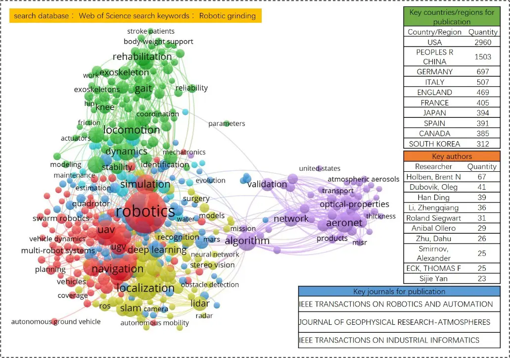
The research on robot grinding system is gradually becoming the key field of academic research and the main direction of the development of manufacturing industry, as shown in Figure 1, through the Web of Science database search keyword Robotic grinding can be seen, in recent years, the research heat and SCI papers on robot grinding system are gradually increasing, more than 300 scholars from more than 80 countries and regions in the world have published a large number of research results in the field of robot grinding. In the past ten years, a lot of research on robot grinding technology has focused on a series of research aspects such as trajectory planning, pose control algorithm, robot kinematics, compliance force control, deep learning, etc. The main sending countries and regions include China, the United States, Germany, Italy, and Britain.
Despite the significant advantages of robotic grinding, its practical application still faces core challenges, mainly due to the inherent limitations of industrial robots. Firstly, the rigidity is insufficient and varies with the pose; secondly, the motion accuracy is low, which is limited by the gear clearance, joint friction, and motion coupling of the reducer; thirdly, there is a vibration control problem, and grinding chatter needs to be analyzed and avoided to ensure process stability. Together, these factors greatly affect the surface quality and profile accuracy of robot grinding [11,12,13,14,15,16,17,18]. In view of the persistent core challenges identified above—particularly the inherent limitations of industrial robots regarding stiffness, positioning accuracy, and vibration susceptibility, which collectively lead to insufficient machining accuracy, large fluctuations in grinding force, and poor surface quality consistency—this review paper is compiled with a clear purpose. We posit that the attainment of high-precision robotic grinding fundamentally depends on synergistic advancements across three interconnected domains: meticulous kinematic analysis and optimized motion planning to enhance path accuracy and smoothness; sophisticated compliance control strategies to stabilize tool-workpiece interaction forces; and intelligent process optimization aimed at achieving uniform and efficient material removal under strict surface integrity constraints. Accordingly, the primary objective of this paper is to deliver a structured and critical synthesis of the state-of-the-art in robotic grinding technology, with a specific focus on recent developments and research hotspots within these core areas.
Following this structured analysis, the paper aims to offer insights into promising research directions capable of overcoming the identified bottlenecks and enabling wider adoption of robotic precision grinding.
2. Frontier Hotspots and System Overview of Robot Grinding
The robotic grinding system is an advanced automation solution that combines industrial robots with grinding processes. It utilizes the flexibility, programmability, and high repeatability of the robot, combined with special grinding tools and sensing technology, to achieve efficient, consistent, and high-quality surface treatment of complex curved surfaces and irregular shapes.
2.1. Evolution and Milestones of Robot Grinding Technology
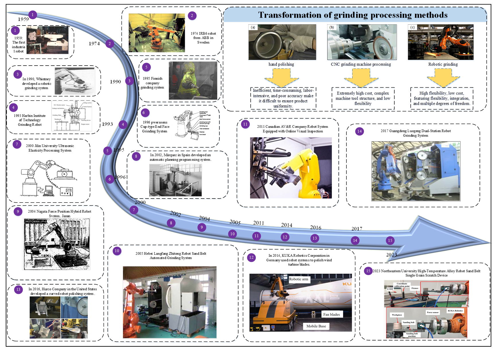
The United States developed the world’s first industrial robot in 1959. After entering the 1980s, the United States began producing the second generation of robots with visual detection and force feedback, quickly occupying the robot market. ABB Company of Sweden developed the world’s first fully electronically controlled industrial robot, IRB6, in 1974, which is mainly used for workpiece picking and placing and material handling [19]. The rapid development of robot technology and the continuous improvement of industrial robot control accuracy make industrial robots widely used in automatic grinding processing systems [20,21,22]. The early industrial robot grinding system mainly uses the robot arm to grasp the abrasive tool and grind the workpiece with a simple shape and low precision requirements. Whitney et al. [23,24,25,26] used a PUMA 560 robot equipped with flexible grinding tools in 1992 to finish cast iron stamping dies to smooth, regular, and accurate final shapes. The robot can execute an arbitrary force trajectory under the condition of workpiece fixture error, and realize automatic weld grinding. In 1995, ORAS [27] introduced the ABB robot system to upgrade the stainless-steel faucet production line. The system adopts a workpiece grinding method, and the robot clamps the faucet workpiece close to the grinding machine to realize grinding processing. Pwersoons et al. [28] performed robotic heavy duty cup face grinding of gray iron workpieces in 1996 using resin bond wheels. A dynamic model is proposed to predict the profile of the workpiece during grinding. A robot deburring strategy for small and large workpieces is proposed [29].
Robot grinding research is moving towards high precision machining with the development and breakthrough of robot key technology in developed countries. In 2002, Spain Márquez et al. [30] developed an automatic planning and programming system for robot grinding based on CAD system data, considering the use of constant contact force control in the machining process to achieve process automation. In 2004, Nagata et al. [31] developed a high precision polishing robot with a hybrid position/force controller, which can effectively eliminate the influence of complex surface shape factors on grinding quality in the robot grinding process. The grinding system developed by Canadian AV&R Company in 2011 is equipped with an online vision inspection system, which can capture the size deviation of the blade profile in real time. It adopts a modular design and supports fast switching between abrasive belt and polishing wheel, greatly saving machining time compared to the traditional offline inspection method. With the development of robot technology, the robot grinding system is used for complex surface machining and polishing, the Germany KUKA company in 2014 robot grinding processing application for glass fiber wind turbine blades, creating a mobile processing robot system, respectively, giving different solutions for wind turbine blade grinding. In 2016, Hurco Company of the United States integrated robot high-precision motion control technology and developed a robot grinding system suitable for curved surface machining. It realized adaptive machining of complex curved surfaces through a six-axis attitude control algorithm. Its customized flexible clamping tooling system achieved Ra0.2 μm surface roughness in precision machining of integral bladed disks [32,33,34,35].
The research on robot grinding and the research and development of the grinding system in China have also achieved remarkable results. In the 1990s, Harbin Institute of Technology developed a HITDM-1 grinding robot that was managed and controlled by a computer through demonstration. The teaching track of the robot was detected by the code disk and stored in the computer [36]. In 2000, Jilin University carried out research on a robot ultrasonic elastic machining system, established the control model of a robot machining system for free-form surface, and verified the feasibility and technical advancement of the scheme through experiments [37]. In 2005, Hebei Langfang Zhitong Robot Company built a robot belt automatic grinding system, which combined the grinding head polishing and the integrated polishing method of seven-axis linkage belt polishing, greatly improving the surface quality and profile accuracy of the compressor blade [38]. In 2012, Beihang University designed a grinding unit with force control function and online adjustment function of the contact wheel, which can realize online error real-time compensation and an automatic replacement robot, which can not only compensate various errors of the robot system in real time, but also ensure that the workpiece contacts the polishing wheel when the radius of the polishing wheel changes greatly [39]. In 2017, Huazhong University of Science and Technology proposed a trajectory and force scheduling method. It gave an optimization model with joint velocity, acceleration, and robot feed rate, with grinding acceleration constraints to maximize robot feed rate [40]. Chongqing University uses the advantage of low cost of robot, uses the grinding head structure with a floating belt compensation function to grind blades, and explores the feasibility of floating belt compensation technology applied to blade robot belt grinding [41]. The automatic grinding system of the double-station robot developed by Luo Geng of Guangdong Province adopts off-line programming to determine the theoretical machining path. It combines the force and position hybrid control to carry out online correction to realize the adaptive control of grinding machining [42]. In 2023, Northeastern University carried out a single abrasive grain scratch experiment based on robot belt grinding, studied the removal behavior of high temperature alloy robot belt grinding, analyzed the rule of scratch length, removal depth, and accumulation ratio changing with grinding speed and grinding depth, and provided an important reference for optimization of the robot belt grinding process [43]. Through a large number of research and practice at home and abroad, it has been proven that robot grinding can indeed bring more advantages than manual grinding, with higher reliability and production efficiency, and its future market breadth is immeasurable, we have summarized the development history of robot grinding technology, as shown in Figure 2.
2.2. Composition and Classification of Robot Grinding Systems
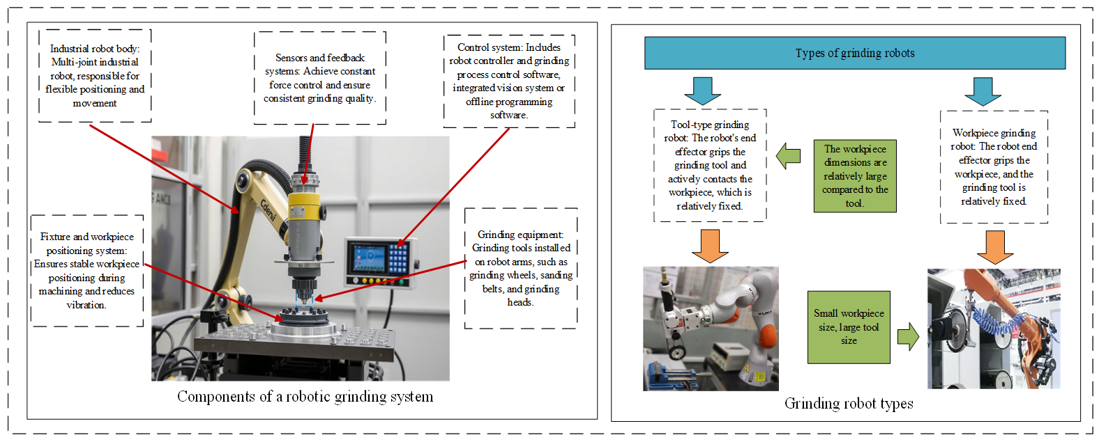
Robot grinding system is usually composed of industrial robot, grinding equipment, control system, sensor and feedback system, fixture and workpiece positioning system several key parts, as shown in Figure 3, where industrial robot is the core of robot grinding system, responsible for the execution of grinding action, grinding tools according to the basic shape and method of use divided into two categories: The control system of fixed abrasive tools (such as grinding wheel, grinding head, oilstone, etc.) and coated abrasive tools (such as gauze, sandpaper, abrasive belt, etc.) is responsible for controlling the motion track and grinding parameters of the robot. To improve grinding accuracy, robotic grinding systems are usually equipped with sensors for real-time monitoring of forces and displacements during grinding, thereby adjusting grinding parameters [44].
Grinding robots can be divided into tool-type grinding robots and workpiece grinding robots. A Tool-type robot through the robot end effector clamping tool active contact workpiece, workpiece is relatively fixed, this way is usually used in the robot’s load capacity is poor, generation of workpiece quality and volume are large. The workpiece type robot grasps the workpiece through the robot end effector, the processing tool is relatively fixed, and the grinding process is completed through the workpiece’s close contact. It is usually used for the workpiece grinding robot with a small size and high grinding accuracy. Lakshminarayanan et al. [45] Fix the belt grinding machine at the end of the robot through the flange. An adaptive learning controller based on impedance control is proposed. The controller adjusts the position and force simultaneously in each iteration to adjust the polishing process. Zhang et al. [46] fixed the parts at the end of the robot. It developed a hybrid force/position anti-interference control strategy based on fuzzy PID control to improve the grinding quality of aviation blades. However, when the two control strategies are adopted, the robot needs to control the position and force of the end effector simultaneously, and it is difficult to ensure good force control accuracy.
The key issue in achieving precision machining with robotic grinding lies in accurately managing the contact force between the tool and the workpiece. Different approaches to handling this contact force have given rise to various robotic grinding methods, which can be broadly categorized into position control, active force/torque control, passive compliance, and hybrid control. Position control adjusts the relative position between the tool and the workpiece. It relies on high-precision programming and path repeatability, imposing stringent requirements on robot rigidity and workpiece consistency. This method is suitable for rough machining of geometrically simple parts or for scenarios assisted by flexible tools. Active force/torque control dynamically adjusts the robot’s posture through real-time sensor feedback, effectively compensating for various errors and enabling high-quality, stable machining of complex surfaces. However, the system is relatively complex and costly. Passive compliance uses mechanical devices to buffer contact force. It offers low cost and quick response, making it suitable for medium- to low-precision applications where some deviation is acceptable. Finally, hybrid control combines position and force control strategies, balancing efficiency and precision, though the programming logic is more complex.
In summary, the choice of method should be based on workpiece requirements, precision targets, and overall cost considerations. Among these, active force control has increasingly become the mainstream approach for high-demand applications, thanks to its significant enhancement of quality and stability.
2.3. Current Research Status of Robot Grinding Processes
Robotic grinding systems are increasingly vital in modern manufacturing, particularly in aerospace, automotive, mold manufacturing, and complex surface processing. The quality of grinding directly determines the service life of workpieces, assembly accuracy, and the overall performance of the final product. As shown in Figure 4, as a core evaluation indicator of final surface quality, the surface parameters of workpieces ground by robots directly reflect the comprehensive performance of the processing system. By optimizing the robot’s posture to maintain optimal stiffness and employing high-rigidity end-effectors and work-holding fixtures, the surface quality after grinding can be improved. Installing a six-axis force/torque sensor at the robot’s wrist or flange end enables the system to monitor in real time and precisely control the contact force between the grinding tool and the workpiece, achieving compliant robotic machining. High-precision offline programming and simulation software for robotic grinding systems can directly generate robot processing paths, which undergo rigorous collision detection and reachability analysis. This ensures a high degree of consistency between the theoretical trajectory and the actual executed trajectory, thereby producing geometric profiles that meet design requirements. These technologies enable robotic grinding surface quality to gradually meet precision manufacturing standards, demonstrating the potential to replace traditional CNC grinding machines.
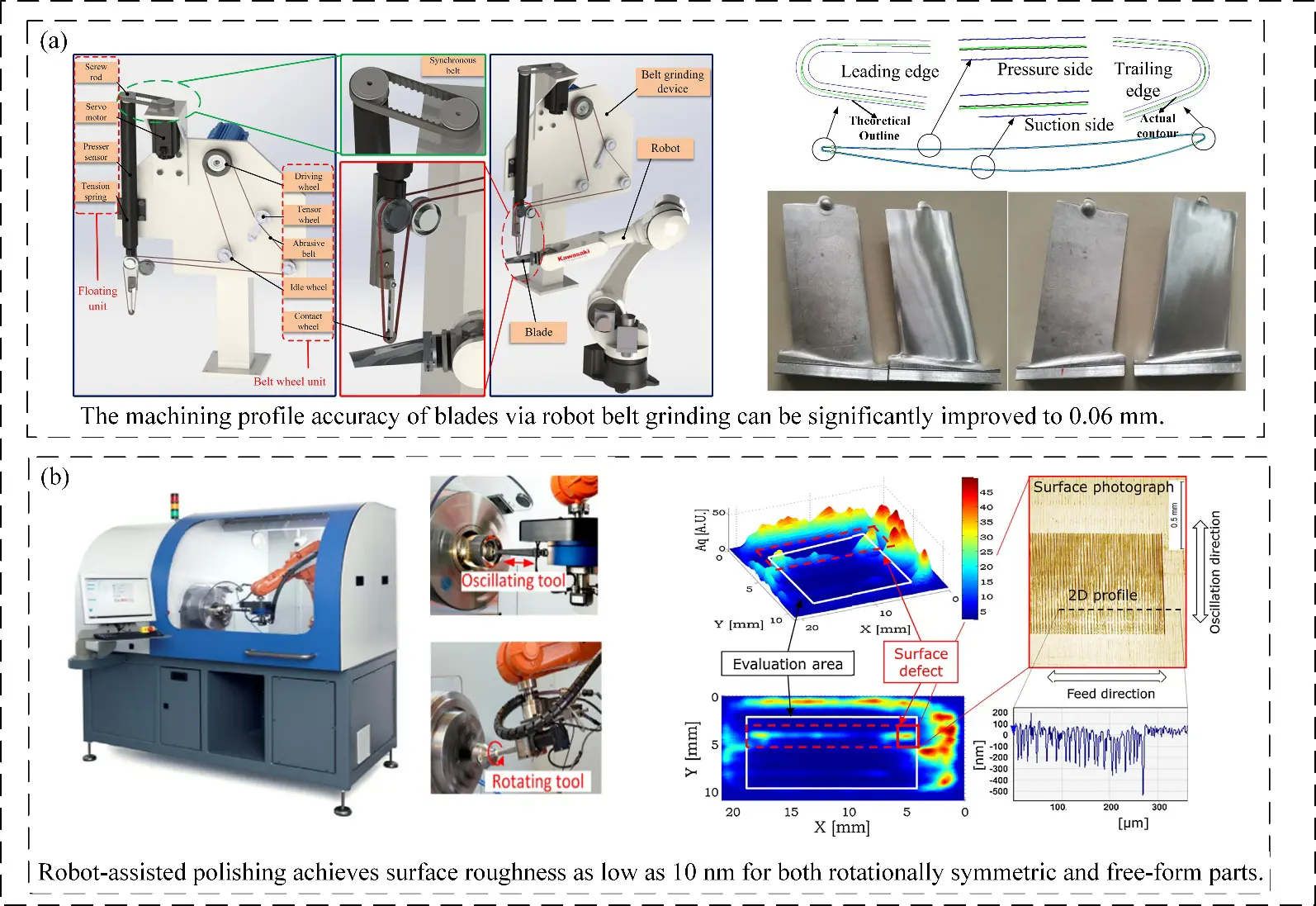
Figure 4. Surface quality after robotic grinding: (a) Blades after robotic belt grinding; (b) Surface after robot-assisted polishing.
With compact structure, high motion flexibility, and cost advantages, industrial robots promote the evolution of grinding technology to standardization and universality, gradually replace manual and CNC machine tools, and face high-precision complex surface machining. There are many grinding processes based on industrial robots, mainly belt grinding, disk grinding, ball head grinding, airbag grinding, etc. Each process has its own characteristics, which are applied to different fields, and its processing requirements are also different.
Due to their different physical mechanisms, various processes put forward different requirements for robot stiffness, force control accuracy, and trajectory planning, which together constitute a robot grinding solution system for different industrial scenarios. Figure 5a shows that the belt grinding process adopts a rubber contact wheel and a flexible belt to form an elastic machining system. When processing the surface with abrupt curvature, the elastic deformation characteristics of the rubber material enable the belt to adapt to the complex profile, effectively avoiding the over-cutting or under-cutting caused by rigid machining, and solving the machining problem of blade complex curved workpieces. Zou et al. [47] designed an abrasive belt grinding device with a floating compensation function to reduce machining errors and carried out a series of grinding experiments on aluminum alloy blades. The experimental results show that the profile accuracy can be improved to 0.06 mm and the surface roughness can be less than 0.4 μm under the optimum parameters. Zhang et al. [48] proposed an adaptive sliding mode iterative constant force control method for a 6-DOF robot with a grinding platform based on a 1-D force sensor, which improved the grinding quality and efficiency of the robot. Disc grinding tools are most widely used in the robot grinding process, as shown in Figure 5b. Zhang Tie et al. [49] developed a robot disc machining system based on a floating platform, and proposed a constant force grinding strategy of linear automatic disturbance rejection control. The experimental results show that the linear ADRC can significantly reduce the force fluctuation in the stable grinding process of the robot, and greatly reduce the surface roughness of the grinding workpiece. Feng et al. [50] proposed an automatic polishing method for curved metal parts. In order to control the contact force, the relationship between the displacement of the polishing disk and the impact force on polished parts is established. According to the specific process parameters, the pressure distribution model of plane and curved polishing in the contact area between the polishing disk and polished parts is derived. Figure 5c is a ball head grinding tool often used for milling in CNC machine tools. With the development of robot technology, ball head grinding tools are gradually applied to robot automatic grinding. Hertzian contact theory is commonly used in ball grinding, through which a more accurate material removal model can be obtained to achieve a uniform material removal rate on the workpiece surface. Yang et al. [51] proposed a method to obtain the local removal rate of the small aspheric lens mold polishing process using a spherical tool. When a small spherical polishing tool is moved on an aspheric surface, uneven polishing areas and local removal rates are generated around the contact points according to curvature changes of the aspheric surface. The model proposed by Fan et al. [52] assumes that the material removal rate follows the Preston equation and that the pressure distribution in the contact region is Hertzian. The effect of tool attitude (described by tilt angle and pitch angle) on the local material removal profile was modeled and analyzed. Wu et al. [53] proposed a new force-controlled spherical polishing tool for an automatic polishing process, which combines rotation and co-rotation motion. The polishing force fluctuation caused by robot positioning error can be effectively reduced, and a stable, symmetric Gaussian removal function can be obtained. The precision of polishing force and the convergence efficiency of the workpiece surface are improved obviously. In robot airbag grinding, an inflated airbag has elasticity and can fit complex curved surfaces, so it is often used for optical element processing, as shown in Figure 5d. The airbag grinding advantage is that it does not scratch the surface of the component; the polished workpiece surface quality is high. Lee et al. [54] proposed a novel bladder-tool polishing technique for small aspherical glass lens molds. For mold materials such as tungsten carbide, ultra-precision grinding techniques are used to produce aspheric surfaces. The final surface roughness is Ra2 nm. Microscopic observations also revealed a cleaner, scratch-free surface. Figure 5e illustrates robotic grinding with a grinding wheel. Robotic grinding with a grinding wheel employs an end-of-arm tool similar to the wheel on an angle grinder, mainly used for heavy stock removal, weld seam grinding, and rough machining. This process generates significant forces and vibrations, thus requiring high-rigidity heavy-duty robots. Ge et al. [55] and colleagues utilized a robotic grinding wheel system to process weld seams, aiming to improve assembly accuracy and surface integrity of structural components. By modeling the grinding force contact mechanics of the wheel and simulating the material removal process during actual grinding, they investigated the influence of grinding wheel process parameters on the machined surface. As shown in Figure 5f, flap wheel grinding is another approach. A flap wheel consists of multiple overlapping abrasive cloth flaps, which expose fresh abrasives as they wear, giving it a long service life and gentle cutting force. It combines both grinding and polishing functions. Derived from abrasive belts, the flap wheel not only inherits the advantages of belt grinding—such as high efficiency and good surface finish—but also offers additional benefits, including adjustable abrasive cloth shapes, simple mounting structures, good accessibility, flexible surface conformity, and cool-state polishing. These features make flap wheels widely applicable. Zhang et al. [56] and colleagues applied a robot-controlled flap wheel to polish investment-cast blades. After polishing, the blade surface roughness reached Ra ≤ 0.4 μm, while the overall profile accuracy of the blade surfaces was maintained within ±0.05 mm.
The selection of tools primarily depends on the workpiece material (metal, composite, glass, stone, etc.) and the processing objectives (deburring, weld seam grinding, rough grinding, or fine polishing).
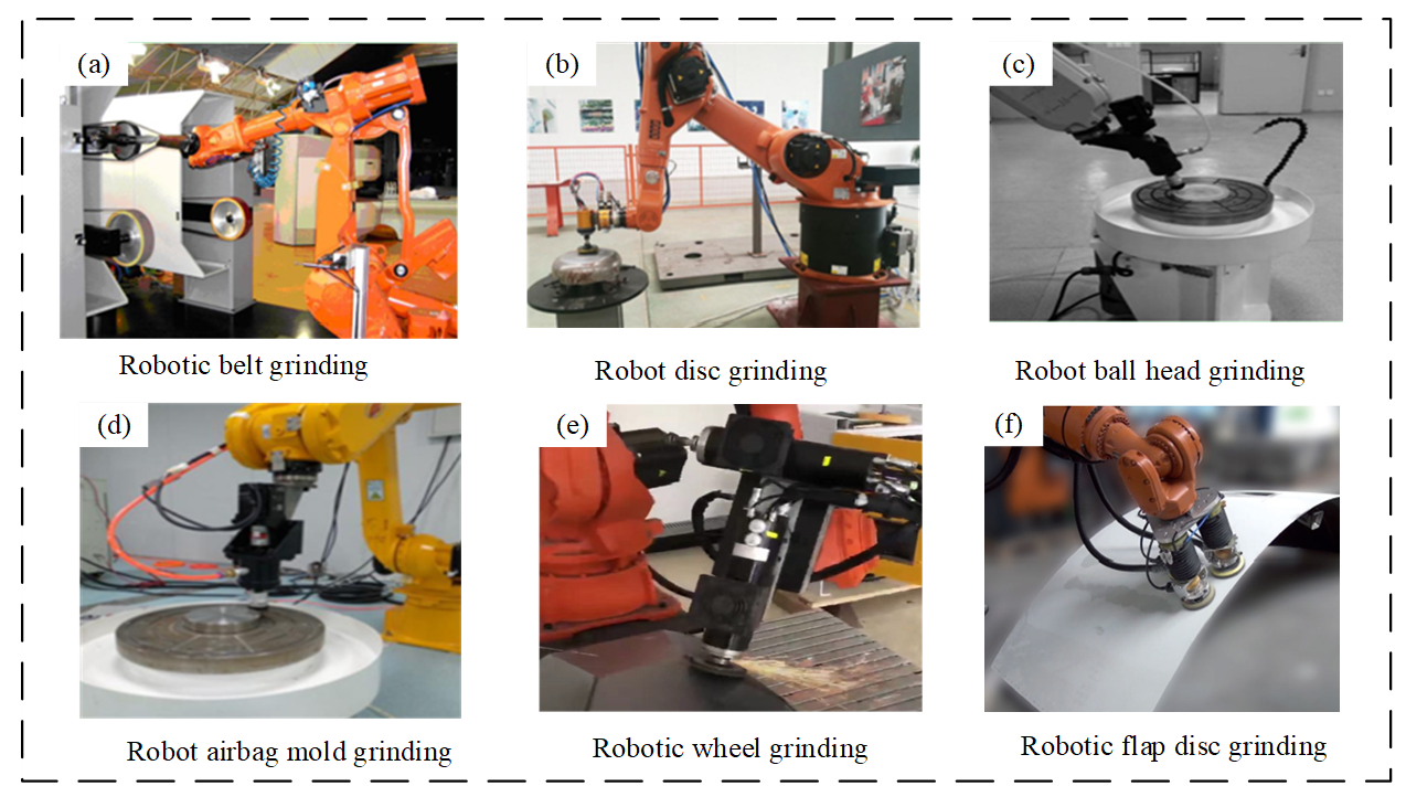
Figure 5. Robot grinding process: (a) Robotic belt grinding, (b) Robot disc grinding, (c) Robot ball head grinding, (d) Robot airbag mold grinding, (e) Robotic wheel grinding, (f) Robotic flap disc grinding.
3. Stiffness Optimization of the Robot Machining System
Robot stiffness refers to the ability of the robot structure to resist deformation when subjected to external forces. It is a key index of robot precision and performance. Compared with CNC machine tools with high stiffness, industrial robots have relatively low stiffness due to their structural characteristics of open chain and series links, which is the main bottleneck affecting their precision machining applications. On the one hand, the weak stiffness of the robot will lead to the reduction of trajectory machining accuracy; on the other hand, the weak stiffness will lead to the deterioration of cutting stability and the degradation of machining quality. Moreover, the weak rigidity of industrial robots will lead to poor machining quality, and it is difficult to obtain ideal surface machining quality and machining accuracy [57].
3.1. Stiffness Modeling Method and Performance Evaluation Index of the Robot
3.1.1. Stiffness Modeling Method of an Industrial Robot
In a robot machining system, stiffness also reflects its machining ability and its ability to maintain positioning accuracy under machining load. As shown in Figure 6, different methods for modeling robot stiffness are presented, along with the actual contour. From the cutting point of view, robot stiffness directly determines its tolerance to cutting load, and then affects the selection of process parameters and cutting parameters in the machining process [58]. Lipkin et al. [59] combined with the robot body structure characteristics, elaborated the robot system stiffness characteristics, and defined the coupling relationship between the load direction and deformation direction, on this basis, proposed the idea of stiffness ellipsoid, described the robot stiffness center, and visually demonstrated the basic characteristics of robot stiffness from the physical and geometric angles. Li et al. [60] realized the stiffness modeling of hybrid redundant robot based on structural analysis and evaluated the basic properties of stiffness matrix by matrix structural analysis method. Shneor et al. [61] defined the minimum collinear stiffness value to evaluate the stiffness characteristics of a 5-axis series-parallel hybrid manipulator, and solved the local stiffness and global stiffness characteristics of the manipulator in engineering applications. For serial robots, the stiffness characteristics are generally divided into link stiffness and joint stiffness, and joint stiffness has the most significant effect on robot performance. For an industrial robot machining system, joint drive servo stiffness and joint transmission structure stiffness are the main factors affecting robot stiffness performance, and their combined action can be regarded as linear elastic torsion deformation at joints [62]. Abele et al. [63] proposed a Cartesian stiffness calculation method based on polar coordinate stiffness, evaluated the robot’s machining performance and solved the stiffness matrix. Zhou et al. [64] proposed a new robot calibration algorithm, which can identify joint compliance and kinematics parameters of industrial robots, compensate for kinematics errors and compliance errors of industrial robots, and improve the positioning accuracy of industrial robots. Slavkovic et al. [65] used the Jacobian matrix and the joint flexibility matrix obtained from experimental identification to establish a stiffness model of the 5-axis serial robot, and analyzed the influence of individual joint flexibility on the Cartesian three-dimensional stiffness one by one, as a basis for optimizing the end force and correcting the robot processing trajectory. Klimchik et al. [66] coupled the influence of link gravity on robot stiffness, and adopted the virtual axis method to integrate gravity and end load into the stiffness modeling process, further improving the accuracy of the model, and verified the effectiveness of the method by numerical simulation and experimental evaluation.
3.1.2. Evaluation Index of Robot Stiffness Performance
The stiffness matrix obtained by the robot stiffness model is a Cartesian space stiffness matrix. Although it can fully reflect the stiffness characteristics of the robot in a certain posture, the stiffness matrix is a tensor measure of robot stiffness, which cannot directly express the quality of robot stiffness performance. The Rayleigh quotient, force ellipsoid, and stiffness ellipsoid are three common scalar evaluation indices of robot stiffness performance, which can directly and quantitatively evaluate robot stiffness characteristics. The Rayleigh quotient is defined as the ratio of the square of the external force vector modulus to the square of the corresponding deformation vector modulus. The Rayleigh quotient reflects the distribution of stiffness performance of the robot under different postures. Therefore, when the end of the robot is loaded, the larger the Rayleigh quotient, the stronger the robot’s ability to resist deformation and the greater the stiffness. The physical meaning of the force ellipsoid is to measure the maneuverability of the robot. The shorter the spindle length, the better the maneuverability of the robot, and the worse the stiffness in this direction. On the contrary, the longer the main shaft, the better the stiffness in this direction and the worse the operability. The Jacobian matrix is closely related to robot pose, so the force ellipsoid also depends on robot pose and changes with robot pose. When the force ellipsoid is close to a circle, robot operability tends to be isotropic, and there is consistent load transmission ability in all directions [67]. The stiffness ellipsoid describes the robot in the current pose, and the spatial distribution of stiffness reflects the basic mechanical performance of the robot, which is the basis for further research on robot stiffness characteristics [68]. The three stiffness performance evaluation indexes can reflect the stiffness characteristics of the robot body in a specific posture, obtain the direction of maximum and minimum stiffness of the robot body, and measure the average level of stiffness of the robot body in a specific posture.
3.2. Coupling Relation between Robot Attitude and Stiffness
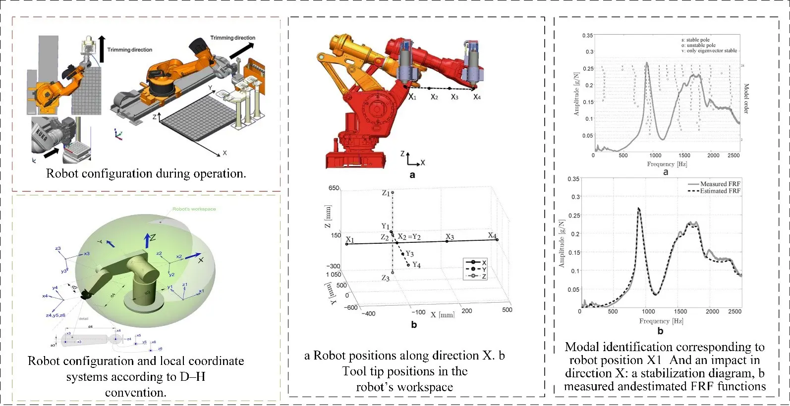
From the transfer relation of the stiffness matrix in angle space and Cartesian space, it is not difficult to find that the flexibility matrix of the angle joint has a decisive influence on the Cartesian stiffness of the robot. Usually, when a robot completes assembly, each angle joint is in a stable state, and its equivalent torsional elastic coefficient can be considered a constant, so the flexibility matrix of the robot’s angle joint can be considered invariant and not changed by external factors. Another factor affecting the Cartesian stiffness of the robot is the Jacobian matrix. The robot kinematics model directly controls the Jacobian matrix; the robot’s working posture determines Jacobian matrix properties. The Jacobian matrix is different for different robot postures, thus revealing the reason why robot stiffness characteristics vary with postures. Choosing a suitable robot processing attitude is of great significance in improving robot processing performance, expanding the processing parameters range, and improving processing quality and efficiency. As shown in Figure 7, the figure illustrates the coupling relationship between different robot poses and stiffness. Slamani et al. [69] Take the conditional number and rank of the Jacobi matrix of the robot as observation objects to measure the posture of the robot. Experiments show that although the robot has similar kinematic performance under different postures, there will be obvious differences in machining quality. By adjusting the distance from the workbench to the robot base and shortening the distance from the machining end to the robot base, the machining quality of the robot will be improved. From this phenomenon, it is found that shortening the telescopic distance of the robot joint arm can improve the stiffness of the robot, and it can be found that posture has an important impact on the stiffness and machining performance of the robot. Vosniakos et al. [70] can reduce the range of required joint torques by using genetic algorithms to select the most appropriate initial pose of the robot relative to the workpiece, thus alleviating the high demands on the robot to some extent. The joint position and torque of the robot are calculated by the inverse kinematics model and inverse dynamics model to minimize joint torque load. The coupling relationship between robot stiffness and pose optimises robot posture. Zargarbashi et al. [71] believe that the processing attitude has an important influence on the load transfer characteristics of the robot after the end force is applied. The robot processing trajectory planning based on kinematic attitude characteristics cannot fully reflect the robot processing performance. So, it is necessary to comprehensively plan the robot processing path and attitude according to the processing task goal and robot stiffness characteristics. Matsuoka et al. [72] use small diameter end mills and high-speed spindles to reduce cutting forces during machining, and use the flexibility of articulated robots to compensate for the cutting accuracy of articulated robots to reduce the impact of low stiffness of articulated robots. To further study the coupling relationship among robot attitude, stiffness, and cutting performance. Rafieian et al. [73] found that the modal characteristics of the robot are different in different postures. For a robot grinding system, it is necessary to measure its natural frequency according to several typical machining postures. Claudiu et al. [74] carried out detailed modal experiments on the KUKAKR240-2 industrial robot to analyze the dynamic behavior of the robot. Three groups of robot postures (P1, P2, P3) were selected in the experiment, and the terminal postures remained unchanged, but the terminal postures were away from the robot base in turn. The modal experiment results show that the stiffness and natural frequency of the X direction are the highest at P3 attitude, farthest from the robot base, and the stiffness and natural frequency of the X direction are the lowest at P1 attitude, closest to the robot base. P3 has the lowest stiffness and natural frequency in Y and Z directions, while P1 has the highest stiffness and natural frequency in Y and Z directions. The experimental results agree well with the theoretical analysis, and the coupling of attitude, stiffness, and frequency characteristics of industrial robots is quantitatively proved. Mejri et al. [75] used the ABBIRB6660 industrial robot to plan 11 test points (4 in X direction, 4 in Y direction, and 3 in Z direction) in sequence in the operation space, expanding the test range of natural frequencies of industrial robots. The experimental results show that the pose significantly affects the natural frequencies of robots. Similarity in robot poses correlates with proximity in their natural frequencies, whereas increased disparity in pose results in a greater divergence in natural frequencies.
3.3. Optimization of Robot Stiffness
The overall stiffness of a robotic system is governed by three principal determinants: the structural stiffness of the linkage elements, which is influenced by their geometric design and material properties; the joint stiffness, particularly in industrial robotic arms, arising from the integrated effect of the drive train’s output torque and the reduction transmission’s rigidity; and the kinematic configuration of the robot, which defines its instantaneous pose and directly affects the distribution of stiffness throughout the workspace. Usually, the methods to improve the stiffness of robots are carried out from the above three points, and the optimization objectives are also optimized by the Rayleigh quotient, force ellipsoid, and stiffness ellipsoid as the reference criteria of the robot stiffness performance index. The method of improving robot stiffness by optimizing link structure is mostly used in the robot design stage. In robot function design, the robot kinematics and stiffness model is established in advance according to the task objective, key geometric parameters of link design are brought into the robot stiffness model, and the threshold of link design size meeting the robot stiffness requirement is solved by calculation. This method is mostly used in selected cases of a robot control system [76]. Another way to optimize the stiffness of a robot is to design a variable stiffness controller. The design idea of the variable stiffness controller is to adjust the output torque of the driving motor according to the requirement of a specific task for robot stiffness, to achieve adaptive optimization of stiffness. To optimize the stiffness of the robot by using a variable stiffness controller, not only accurate and perfect stiffness model needed, but also a complex control system is needed [77]. The above two methods are often used in the robot design stage, and mature industrial robot products are used as processing carriers for robot grinding systems. For mature industrial robots, changing their link structure and enhancing their stiffness is almost impossible. The design of variable stiffness control needs complex communication with the robot servo control system. it is also very difficult to realize variable stiffness control due to the limitation of communication caused by the closeness of robot controller. Therefore, improving robot stiffness tends to start with optimizing robot posture. Andres et al. [78] defined the robot task objective based on the redundant characteristic of industrial robot function when planning the robot processing path, and regarded the position and posture of the robot arriving at the processing point as the first level task, and included the robot kinematics operability as the second level task into the first level task. The significance lies in the fact that the robot adjusts the posture further by using its redundant degree of freedom to arrive at the position and posture. Pei et al. [79] used the robot force ellipsoid as the stiffness performance criterion. By optimizing the working posture of the robot, the maneuverability of the robot in the direction of load action was improved, and the grasping accuracy and efficiency of the robot were also improved. Ajoudanj et al. [80] take the shape and size of stiffness ellipsoid as the evaluation index of robot stiffness performance to measure the basic mechanical characteristics of robot in current attitude; introduce the concept of maximum allowable Cartesian force/displacement region of flexible robot, and discuss the role of different configurations in defining the performance limit of Cartesian stiffness controller, and design a stiffness control method, which can reasonably utilize joint control parameters and redundant solution to realize the required task space interaction behavior.
4. Kinematic Analysis and Motion Planning in Robot Grinding
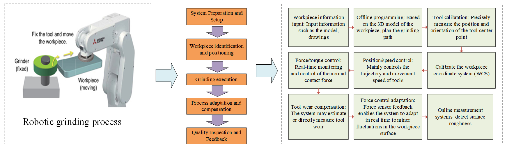
The core of the robot grinding operation is to drive the grinding tool to accurately follow the workpiece contour movement to remove residual material under the premise of ensuring workpiece size tolerance, as shown in Figure 8. The process consists of two key subtasks: precise contour tracking (ensuring that the tool always moves in the direction of the contour) and applying appropriate constant force control (ensuring efficient removal of excess material while avoiding damage to the workpiece or tool). Its working principle is mainly divided into three steps: first, path planning, according to the workpiece geometry and grinding requirements (such as grinding ability, pressure and grinding rate at specific positions) Planning the robot trajectory; then performing grinding, the robot moves according to the planned path, and the grinding tool (or moving workpiece) is processed; finally, through real-time feedback and adjustment, using sensors to monitor parameters such as force/displacement, the grinding process is dynamically adjusted (such as precise positioning using mobile platform) to ensure the processing quality. The motion trajectory of the robot will directly affect processing efficiency and surface quality. Machining trajectories are critical to the uniformity of coverage of the part surface and adapt ation of residence time along the path to achieve uniform material removal. Improper machining path shape, spacing, or feed speed will lead to obvious machining texture and intermediate frequency topography error on the surface, reduce the performance of parts, and directly affect the smoothness of robot motion. Therefore, it is necessary to combine the influence of robot kinematics and dynamics characteristics on the grinding process, improve robot motion accuracy and smoothness by means of error calibration and compensation, processing attitude optimization, and robot motion simulation technology, and finally realize precision machining.
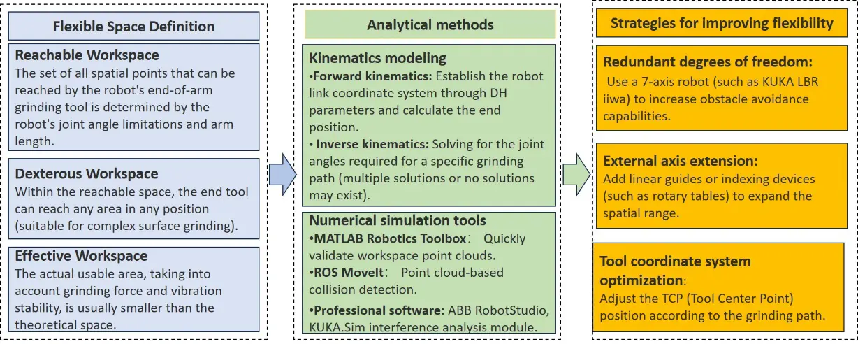
4.1. Dexterous Workspace Analysis for Grinding Robots
Robot dexterity and reachable workspace are important basic characteristics to characterize robot motion characteristics. The dexterity characteristics of robots decisively reflect the task execution ability of robots in the working environment. Therefore, the dexterity analysis of the robot body and the study of dexterity characteristics of the robot can provide a theoretical analysis basis for deeply evaluating the dexterity performance of the robot, analyzing the influencing factors of dexterity performance, and optimizing the structural parameters. As shown in Figure 9, the method and steps for analyzing the flexible space of robotic grinding are as follows:
Vahrenkamp et al. [81] proposed an extension of the manipulability ellipsoid metric that takes into account constraints such as joint constraints or self-distances between the manipulator and other robot parts. The simulation results show how the extended operability metric can be used in the grasping and manipulation pipeline of humanoid robots. Roberts et al. [82] uses kinematics and dynamics-based robot dexterity formulas to introduce a new method of describing joint limit singularities, configurations where one or more joints reach their joint limits, and full control of the end effector is not achieved. Park et al. [83] proposed a mathematical theory to optimize the kinematic flexibility of robotic mechanisms by defining the forward kinematics of mechanisms as a mapping between Riemannian manifolds and applying the coordinate-free language of differential geometry to define natural measures of kinematic flexibility and workspace volume, and obtained a collection of analytical tools for robot design, as shown in Figure 10.
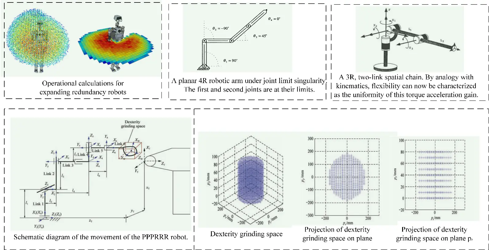
Tchon and Zadarnowska [84] propose an algorithm for managing redundant measurements provided by stereo multi-camera systems to achieve accurate visual tracking of moving objects. The algorithm uses the extended Kalman filter embedded in the efficient pose estimation process of 3D objects modeled geometrically based on binary spatial segmentation trees as a geometric optimization tool in mobile robot design. Gao et al. [85] proposed an optimization strategy of grinding robot structure size and relative wheel position based on the particle swarm optimization algorithm to obtain the required dexterity grinding space.
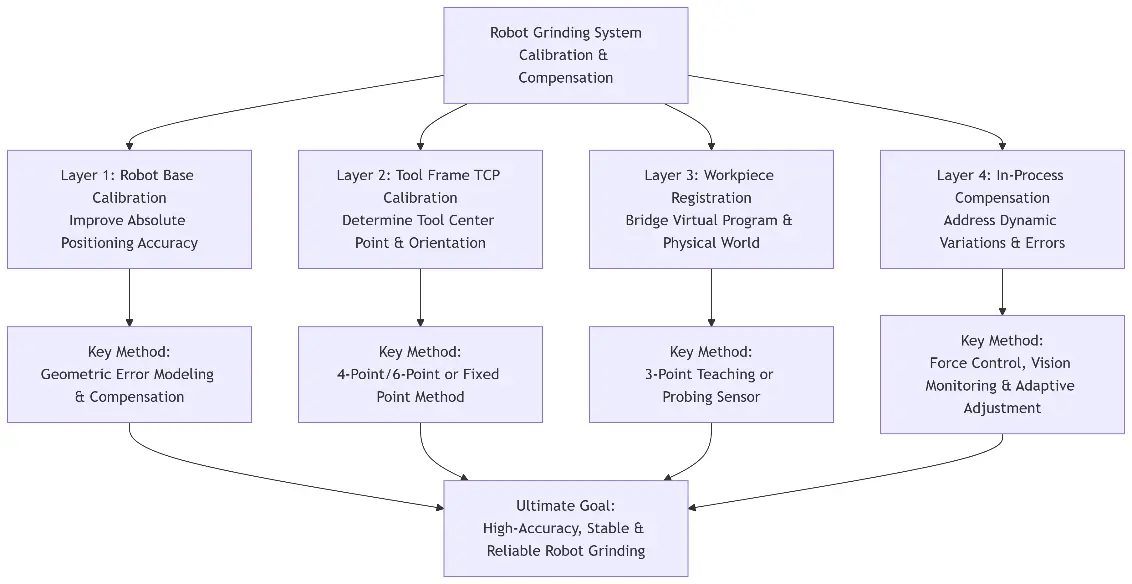
4.2. Calibration and Compensation of Robot Grinding System
In the working process of the robot grinding system, calibration and compensation of the robot grinding system are carried out firstly, as shown in Figure 11, reasonable robot pose is determined, or robot pose in machining is optimized and compensated, robot pose with small stiffness is avoided, dynamic performance index of the system is improved, and accessibility of machining path in machining process of robot system is improved. Calibration and compensation of the robot grinding system are the premise and important guarantee of robot grinding. The identification and compensation of the structure parameters of an industrial robot is the most important part of the calibration and compensation of the robot grinding system. The identification and compensation of robot parameters are mainly divided into kinematics modeling, system measurement, parameter identification, and error compensation. Its main purpose is to identify the parameters of the robot motion model through the measurement of target points, and then optimize these parameters to improve the absolute position accuracy of the robot. Insufficient positioning accuracy of the robot body will cause machining tools to reach the machining position accurately and reach the expected contact state. The improvement of robot positioning accuracy can effectively improve the relative pose accuracy between the grinding tool and the part surface. However, the grinding tool size error, part installation error, part surface deformation error, and other factors will still cause the actual polishing trajectory to deviate from the ideal trajectory. Therefore, it is necessary to calibrate the motion transfer parameters between the “robot-tool-workpiece” multi-coordinate systems to ensure the accuracy of the relative pose relationship between the polishing tool and part surface. The calibration methods of the robot tool coordinate system can be divided into the multi-point repeated positioning method and the external reference method. The multi-point repeated localization method requires the robot end tool to arrive at the same position in different postures many times, and the center point position (TCP) of the tool can be obtained by fitting according to the angle value of each joint and the forward kinematics of the robot. The external reference method generally requires the use of camera, laser tracker and other measuring equipment, establish a closed-loop spatial size chain among the measurement coordinate system, robot base coordinate system and tool coordinate system, track the position of the end tool by measuring instruments, and identify the characteristic parameters of the base coordinate system in the measurement coordinate system and the tool coordinate system in the base coordinate system by combining the forward kinematics of the robot and the measurement data. Aiming at the installation error and surface deformation error of parts, measuring and registering the surface of parts before polishing can increase the contour information of the actual surface obtained and improve the accuracy of its spatial position, thus improving the accuracy of machining tool positioning [86].
The positioning error of the robot grinding process consists of geometric error and non-geometric error, among which geometric error is caused by misalignment of the robot working unit and the difference between nominal value and actual value of robot motion parameters, and it is also the main source of robot positioning error, while non-geometric error mainly comes from joint flexibility error [87]. Kinematic error calibration can be used to compensate for robot geometric errors, which mainly includes four steps: kinematic modeling, robot positioning accuracy measurement, parameter identification, and error compensation. Obtaining the information of the robot terminal position and pose in machining space is the basis of identifying the geometric parameters of the robot [88]. Scholars at home and abroad have adopted various compensation algorithms and measurement methods to improve the absolute positioning accuracy of the robot. As shown in Figure 12, this illustrates the hand-eye calibration and laser tracking calibration methods for different robots. Xu et al. [89] proposed a TCP (Tool Center Point) based calibration method to calibrate the relationship between a pre-calibrated 3D laser scanner and a robotic end-effector by using a standard sphere as a calibration object. Li et al. [90] proposed a new calibration method for robot grinding. Joint parameter error and pose parameter error are considered in the hand-eye calibration equation. The need for expensive and complex tracking processes using laser trackers is avoided. Zhang et al. [91] proposed a new PPPRRR grinding robot. The mathematical model of the grinding path of the robot is established, and the influence of workpiece attitude relative to the terminal joint and contact wheel position relative to the robot base coordinate system {O} on the grinding ability of the system is analyzed. The above attitude and position factors are optimized based on the Monte Carlo method, which improves the grinding capability of the system. Gao et al. [92,93] proposed a new hybrid algorithm combining BP neural network (BPNN) and particle swarm optimization (PSO) algorithm for kinematic parameter identification of industrial robots and enhanced convergence response to solve the problems of slow parameter estimation and control performance lag in traditional adaptive control methods. Based on enhanced local attitude measurement, Klimchik et al. [94] robot calibration and compensation method can calibrate industrial robots in a real industrial environment. A reasonable calibration configuration can be found to ensure the best robot positioning accuracy by establishing a robot geometric model and adjusting attitude.
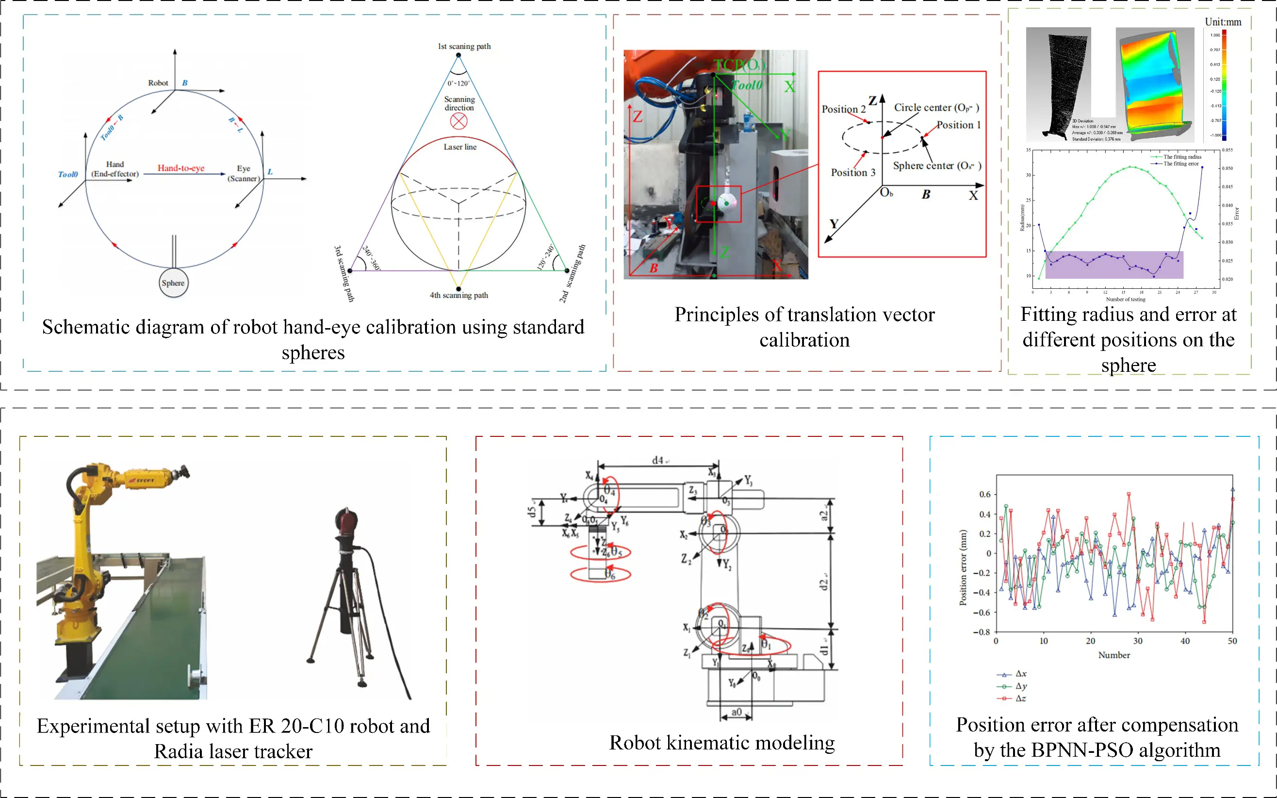
Nubiola et al. [95] proposed a novel 6D measurement system consisting of a commercially available telescope club and two custom fixtures. Of the 72 poses of the tool holder relative to the base holder, six distances between the magnetic cup on the tool holder and the magnetic cup on the base holder can be measured using the club, thereby calculating the poses with high accuracy. Guo et al. [96] proposed a multi-level calibration technique to improve the absolute accuracy of an industrial robot (ABBIRB2400) with a parallelogram mechanism. Zhang et al. [97] analyzes the mathematical model of hand-eye calibration in a robot grinding system, and use a calibration tool with sharp points to quickly obtain measurement data. Based on the original singular value decomposition algorithm, an improved algorithm based on weighting is proposed. Compared with the original algorithm, the average calibration error of the improved algorithm is reduced by 45.9%, and the maximum error is reduced by 24.4%. Deng et al. [98] proposed a hybrid algorithm combining the Levenberg-Marquardt algorithm and squirrel search algorithm based on reverse learning to identify the kinematic parameters of polishing robots, so that the kinematic parameters of robots can be effectively calibrated.
4.3. Robot Trajectory Planning Technology
When the robot performs grinding tasks, the first thing to consider is planning the robot’s execution trajectory. It makes it possible for the robot to drag the grinding tool or workpiece to be ground precisely from one position to another. Grinding path planning and robot machining pose optimization are also key technologies to ensure the machining quality and machining efficiency of parts, and the results of machining path planning will also directly impact the smoothness of robot motion. It is very important to plan the tool path correctly for high precision grinding of a complex curved surface.
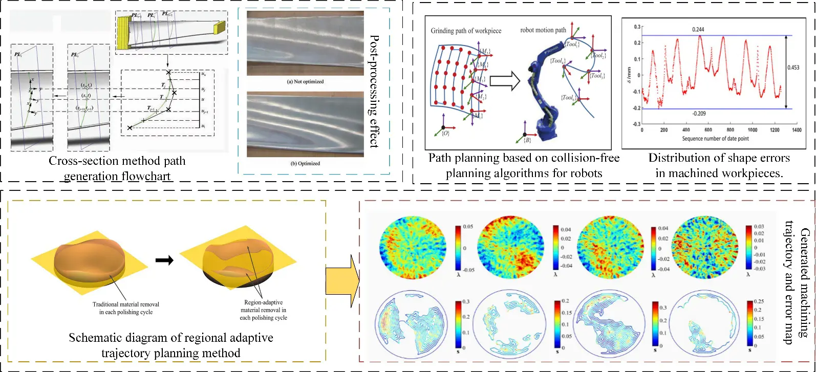
Common trajectory planning methods can be divided into direct and indirect methods. The direct method directly generates machining paths according to geometric constraints such as workpiece shape and size during robot machining. As shown in Figure 13, this is a direct method for robotic trajectory planning. Wang et al. [99] established a grinding path generation method including curve length spacing optimization. The method is verified by off-line simulation, and the grinding experiment improves the surface quality. Wan et al. [100] proposed a new area adaptive path planning method, which adaptively generates paths according to specific shape errors. The polishing time can be reduced by 80%, thus greatly improving the stability and efficiency of robot polishing. Gao et al. [101] proposed an optimal trajectory planning method for robotic arms, using the improved Instructional Learning Optimization (ITLBO) algorithm, which can be applied to any robotic arm to generate time-optimal trajectories. Zhang et al. [102] developed a collision-free planning algorithm for robot motion path based on the collision layer method. The collision-free planning of robot motion path is studied, and the method of adjusting the belt machining frame (i.e., moving along the belt axis and rotating around the tangent) is determined. Neighborhood search and recursion methods are used to find planning curves quickly on collision layers, which significantly reduces the number of collision detections. Planning curves are transformed into robot motion paths.
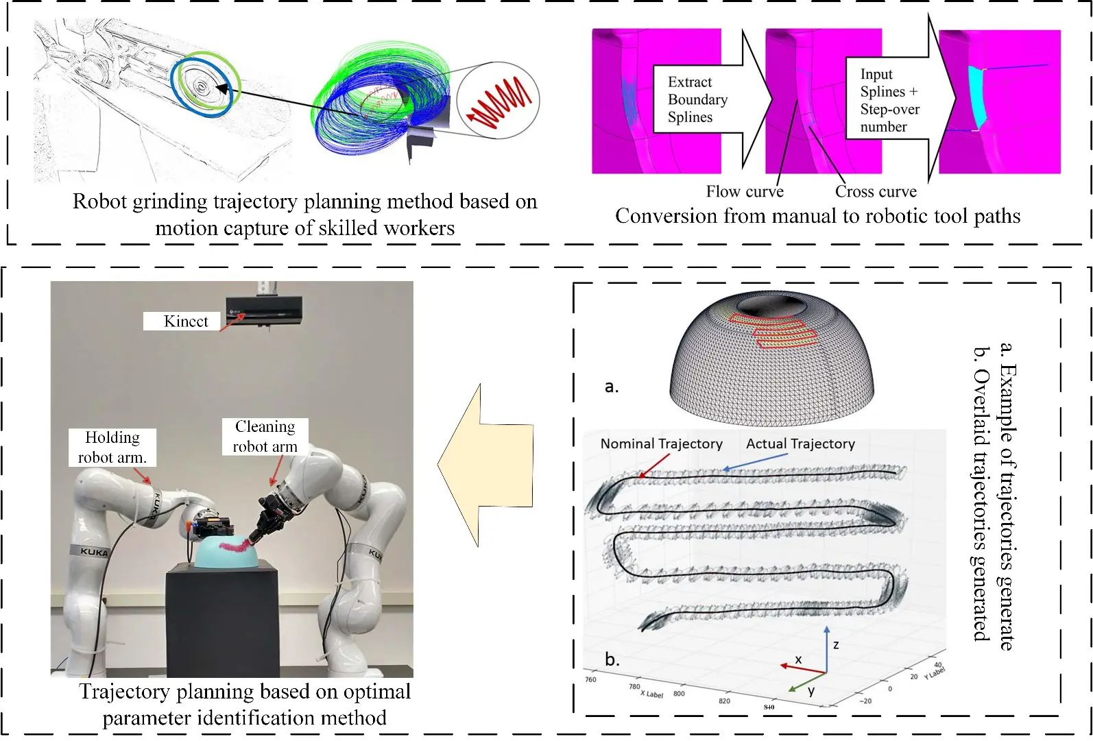
As shown in Figure 14, the indirect method for robotic trajectory planning The indirect method means that the robot searches the path in the constrained space of the grinding structure and obtains the final grinding path according to these constraints (such as machining speed, contact force, average position, etc.). Ng et al. [103] propose a novel approach to reducing the workload of automated manual surface finishing processes by bridging the knowledge transfer gap between manual operator skills and robotic programs. By capturing tool characteristics such as amplitude, velocity, average position, direction of travel, and contact force. Using the inherited trajectory information, linear interpolation and spline interpolation are used to interpolate the robot trajectory, respectively. Through the robot finishing strategy experiment, the workpiece can be machined to within 0.7 mm of the target shape. Kabir et al. [104] propose robot planning algorithms for nonplanar surfaces. By considering kinematics constraint generation of the robot, priority branch-bound search is used to generate a setup plan, so that trajectory parameters converge to the optimal point quickly. Kharidege et al. [105] found that kinematic singularities greatly affect the performance of the robot arm, requiring the use of the determinant of the Jacobian matrix of the robot arm to identify singular regions in the mission space explicitly, and proposed an automatic polishing system scheme consisting of a 6-DOF robot arm. Chen et al. [106] proposed a deformation-based trajectory optimization method by analyzing the relationship between feed rate, deformation, and trajectory planning. Firstly, the relationship among grinding angle, feed speed, deformation, and interpolation point planning is studied, and two speed constraint conditions are proposed. Then adjust the position of interpolation points according to velocity constraints to optimize the trajectory. Experimental results show that the proposed trajectory optimization method can significantly reduce the deformation and vibration during robot grinding. Qi et al. [107] proposed a method of robot grinding trajectory planning and force control for complex surfaces based on DMP generalized mapping. The planned path on the unknown surface shows good grinding effect, good practicability, and stability. Mao et al. [108] proposed an attitude planning method for robot grinding tools based on spherical linear interpolation. The discrete grinding path is fitted to B-spline curve, and the curvature information of the spline path is extracted to identify the critical area of wheel grinding and generate the tool attitude that changes smoothly along the path, so that the grinding stability can be effectively improved.
The direct method generates the robot’s motion trajectory directly based on the geometric shape, dimensional constraints, and processing requirements of the workpiece through mathematical modeling or simulation. It can generate paths directly without the need for multiple iterative optimizations. Characterized by high computational efficiency, it can quickly produce high-quality paths for workpieces with regular geometries and smooth curvature variations. This method is suitable for rough and semi-finish machining of regular surfaces, simple surfaces, planes, or workpieces with uniform contours. However, it performs poorly in adapting to complex surfaces or environments with obstacles. The indirect method involves searching for an optimal trajectory in the configuration space or task space through optimization algorithms under certain constraints. It can handle complex surfaces, multi-obstacle environments, and non-ideal working conditions, demonstrating strong adaptability. Additionally, it can simultaneously consider multiple requirements such as force control, dynamics, and vibration suppression. Integrating real-time sensor data enables adaptive trajectory modifications. However, the computational process is relatively complex and time-consuming, requiring the integration of multiple sensors and advanced control algorithms, which increases system complexity. This method is suitable for precision grinding of complex free-form surfaces (e.g., aerospace blades), force-controlled polishing, adaptive machining, and other scenarios with high demands on contact conditions.
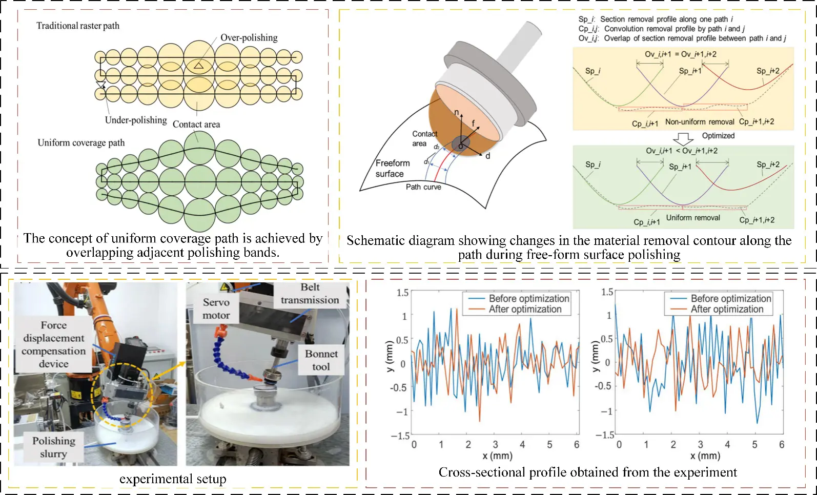
Achieving high precision and uniform material removal is still a key challenge in manufacturing for complex curved parts. From the perspective of material removal uniformity, the grinding contact area can cover the part surface without a gap and uniform overlap, effectively avoiding quality problems such as under/over grinding. For free-form surface parts with complex geometric features, the shape of the contact area will change greatly with the change of local shape information of the part surface. It is necessary to consider the change of contact area shape at different machining positions, adaptively optimize and adjust the distance between adjacent machining paths, so as to reduce the uncovered gap and excessive overlap area in the grinding contact area. As shown in Figure 15, a trajectory planning method for uniform material removal is presented. Han et al. [109] proposed an adaptive polishing path optimization method based on footprint evolution to reduce RMS of the center region of the machined part surface from 5.1766 nm to 4.1448 nm. Although the polishing path planning method using uniform coverage of the grinding contact area can reduce the surface removal depth profile error and surface waviness, it still fails to directly consider the material removal effect in the process planning, and it is difficult to solve the problem of overlapping processing contact areas between adjacent paths. Optimization of width and correction of the removal depth profile fluctuation error. The smoothness of the polishing path will directly affect the smoothness of the robot processing process. Accurate control of the robot contact force to ensure that all polished surface areas have equal removal depth can improve efficiency and reduce the cost and time consumption caused by manual use and traditional polishing machines [110]. Gong et al. [111] proposed a discrete partition algorithm for free-form surface parts from the simplification point of view. The algorithm ensures that the machining equipment can complete each sub-surface and plan the polishing path according to the surface division results to realize the complete polishing process of the surface in the shortest time. In order to improve the smoothness of robot polishing. Liu et al. [112] proposed an improved Douglas-Peucker (DP) algorithm, which can reduce the number of machining path points on the hub surface by considering the change in path point posture. Secondly, it combines greedy best first search (GBFS) and sine cosine algorithm (SCA) to find the optimal joint motion efficiently.
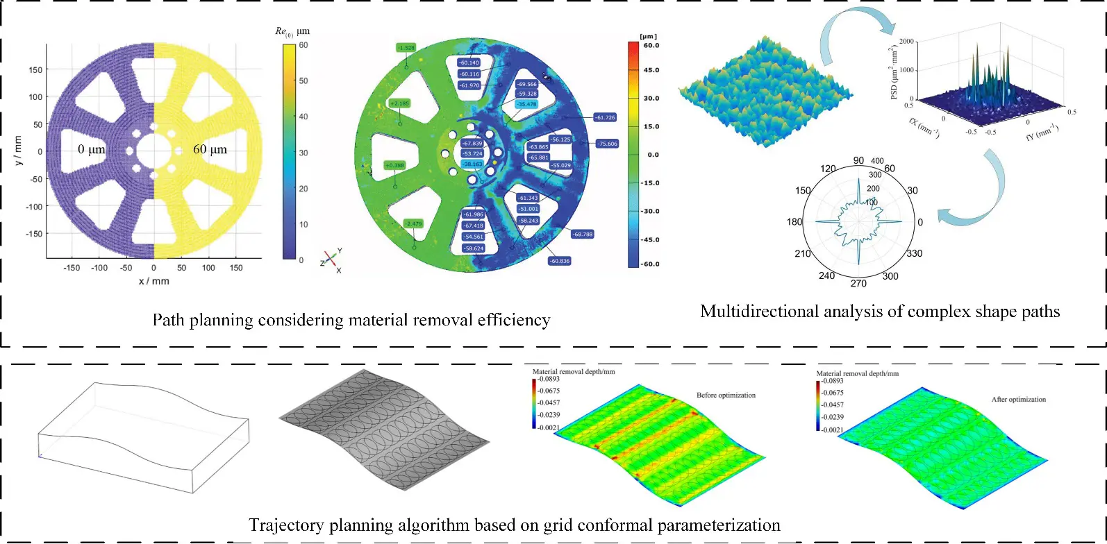
As shown in Figure 16, this illustrates the application of material removal simulation technology in path planning. Applying material removal simulation technology to machining path planning can effectively reduce the surface waviness of parts to the desired value. Deng et al. [113,114,115] developed a numerical contact mechanics model for point-sampled complex workpieces to efficiently predict the contact pressure distribution and material removal depth on the workpiece point cloud, considering the needs of robotic polishing of complex wheel hub parts. Multidirectional paths and adaptively adjusted spacing enable more uniform material removal. Xu et al. [116] developed a new algorithm based on conformal parameterization of mesh, which simplifies cycloidal tool path generation with complex free-form surface into a two-dimensional domain and considers mapping distortion. By accurately calculating the effects of overlapping toolpath trajectories, material removal variations along cycloidal toolpath guide lines are accounted for using optimized cycloidal step sizes and radii. In the real industrial environment, the surface reconstruction of free-form surface can not completely fit the actual surface, and the curvature of a complex surface often changes sharply, resulting in a non-smooth path and incomplete coverage. Liang et al. [117] proposed an integrated robot polishing trajectory planning method using point cloud processing technology. The collected point cloud is preprocessed, including filtering and plane segmentation algorithms. Douglas-Puke algorithm and pose frame estimation are applied to extract the tool tip position and optimize tool contact attitude respectively. Alessandra et al. [118] achieved the minimization of polishing time and the optimal polishing quality of free-form multi-surfaces in an actual industrial environment by controlling the density, overlap, edge distance, and scanning direction of path points, segmenting surfaces based on curvature similarity, and connecting separately calculated trajectories. Zhang et al. [119] created polishing paths by preprocessing and slicing the 3D point cloud of the blade, using point cloud discretization and B-spline curve fitting methods to ensure accuracy errors within 0.1 mm.
To sum up, a lot of research has been carried out on the uniformity of contact area, path spacing optimization considering material removal simulation, complex polishing path planning, and path adjustment based on motion smoothness in the robot grinding process, which have solved the problems of material removal uniformity and machining accuracy in robot grinding process and laid a foundation for robot precision grinding.
5. Force Control and Process Optimization in Robot Grinding
Robot motion control technology is one of the indispensable key technologies in complex robot applications such as grinding, polishing, assembly, and online inspection. Motion control devices with precision, fast dynamic response, and strong adaptability are the foundation for improving robots’ complex working ability and broadening robots’ application field. They are also an indispensable part of robot grinding and intelligent machining. The output torque and high response speed produced by the complex grinding environment will somewhat cause shock and vibration. Excessive impact force will cause instability in the system and easily lead to electromechanical coupling vibration among the electric spindle, grinding wheel, and grinding load. Even the robot body, processing tools, and workpiece surface quality caused serious damage. In order to make the robot polishing system widely used in polishing various workpieces, it is necessary to add compliance control to the grinding robot, which can make the robot change its task quickly and adapt to the requirements of multi-variety machining in the aerospace field. It has a low cost, is fast, and is efficient while improving product production efficiency and quality [120].
5.1. Compliance Force Control Strategies
The robot grinding compliance force control technology is the core of high precision and adaptive machining, especially for complex curved surfaces, abnormal parts, or uneven hardness of materials. This technology can avoid overload or under-machining by real-time sensing and dynamic adjustment of grinding contact force. The traditional scheme to improve robot grinding adaptability usually involves adding a 3D force sensor at the end of the robot and modifying the trajectory of the robot by sensing the change of pressure to achieve pressure maintenance. However, the response speed of the robot is far from meeting the grinding application of high-precision parts. In recent years, robot compliance joint devices include force sensing and pressure maintaining actuators, which can satisfy accurate pressure maintenance and rapid pressure response without changing the trajectory of the robot. The steady-state force tracking ability is the most essential problem of robot force control, so in order to meet the process requirements, it is necessary to integrate modern control theory and optimization algorithm to enable the robot to achieve more accurate force tracking. Active compliance and passive compliance are two core force control strategies in the robot grinding field, which are used to solve the problems of impact, overload, vibration, or poor surface quality when the robot rigidly contacts the workpiece. The core difference is how compliance and force control are achieved.
As shown in Figure 17a, active compliance control refers to the interaction force between the robot and the environment (workpiece) sensed in real time by the force/torque sensor during the actual compliance motion of the robot. Based on this feedback information, the robot’s motion control algorithm is used to actively adjust the robot’s position or force output to achieve the desired contact force or conform to the workpiece surface, mainly including impedance control, force/position hybrid control, adaptive control, and intelligent control [121]. Zhou et al. [122] proposed a new robust sliding mode impedance control method by taking the environmental position uncertainty and the implicit dynamic adjustment term of impedance model parameters as concentrated disturbances and combining the sliding mode variable structure theory. Simulation and experimental results show that the relative contact force error is less than 4.73%. Ye et al. [123] developed a hybrid impedance and admittance control (HIAC) scheme to obtain a second-order target impedance model representing optimal interaction behavior independent of accurate environmental dynamics and acceleration feedback, providing optimal performance for the target impedance model. Wu et al. [124] established a dual-PID adaptive variable impedance control to control the force tracking error within ±0.2 N and improve the workpiece surface roughness to Ra0.218 μm, thus improving the robot grinding performance. Hamedani et al. [125] proposed an intelligent variable impedance control method combined with a fuzzy gain dynamic surface to improve the interaction between the manipulator and an unknown variable environment. Abu et al. [126] proposed a learning and demonstration framework that integrates force sensing and variable impedance control to enable robots to respond satisfactorily to new task conditions. Li et al. [127] established an efficient variable impedance control method that uses a probabilistic Gaussian process model as the transitional dynamics of the internal simulation of the system to achieve long-term reasoning and planning in a Bayesian manner. Then, a model-based reinforcement learning algorithm is used to search for the optimal impedance regulation strategy. Experiments show that this method can improve the flexibility of the system. Dong et al. [128] proposed the concept of force/position hybrid drive for developing human-machine friendly robot systems. Experimental results show that a hybrid drive can significantly improve the performance compared with the drive system using pneumatic artificial muscle only. Chiaverini et al. [129] studied the stable position/force adjustment of a robot manipulator with elastic flexible surface contact. By using the classical Lyapunov method and LaSalle invariant set theorem, the asymptotic stability of the system near the equilibrium state was proved. Ravandi et al. [130] solves the problem of hybrid force/position control of manipulator in an uncertain environment by combining fuzzy logic with traditional sliding mode control (SMC). Rani et al. [131] develop an intelligent controller for hybrid force and position control of robot manipulators with external disturbances and model uncertainties. By using a radial basis function neural network to identify the nonlinear function of model dynamics, the function of the adaptive boundary part is to estimate the boundary of model disturbance, the friction term, and neural network reconstruction error.
As shown in Figure 17b, passive compliance refers to adding a physical flexible structure (such as springs, dampers, pneumatic elements, elastomers, etc.) between the robot and the tool/workpiece. Wang et al. [132] proposed a new passive compliance control method by using the elastic deformation of the structure to absorb shocks and adapt to geometric errors or positional deviations. A passive compliance grinding device is designed to reduce the fluctuation of the normal grinding force of the robot, and its mechanical modeling and analysis are carried out. Considering the elastic deformation of the contact wheel, inherent precision error of the robot, uneven distribution of grinding allowance, and weak blade stiffness, a control model of the robot normal grinding force is established to maintain its stability. Huang et al. [133] proposed a hybrid force/position control strategy for a robot grinding system based on a passive compliance device. A compliance device is installed at the end of the robot to decouple the force control and position control of the tool end. Good surface quality is obtained by grinding and polishing the aviation blade. Passive force control devices maintain a constant contact force between the polishing tool and the workpiece by means of flexible support elements, and their force control performance depends on the compliance and stability of their overall structure. With the development of material technology and structural design optimization methods, some complex variable stiffness mechanical structures are applied to the design of robot terminal force control devices. Combined with stiffness modeling, structure/size parameter optimization and other technologies, contact force overshoot and steady-state control error are reduced. However, this kind of actuator lacks the ability to respond actively, and its force control performance is greatly affected by the external environment, especially in the polishing of complex curved parts. The change of tool attitude will cause large contact force error, making it difficult to be competent for more complex polishing tasks. In order to solve the above problems, low impedance series elastic actuators can be developed by adding elastic elements to the main power control device to improve the compliance of the output force. Chen et al. [134] developed an active compliance force control end-effector based on series elastic actuators for robotic surface grinding, as shown in Figure 17c. The grinding results show that the maximum force control error of the flexible force control end effector is reduced by 70% compared with the rigid force control end effector, and the overshoot of force control is reduced from 30% to nearly 0 at the same response speed. In summary, different compliance force control strategies each have their own advantages and disadvantages. Their selection requires careful consideration of factors such as force control accuracy, response speed, system complexity, cost, and dependency on environmental models. Each compliance force control strategy is suited to different application scenarios. Based on research findings from domestic and international scholars, this paper summarizes the characteristics and suitable application scenarios of various compliance force control strategies, as shown in Table 1.
Table 1. Comparison of Different Compliance Force Control Strategies.
Control Strategy |
Application Scenarios |
Advantages |
Disadvantages |
|---|---|---|---|
Impedance Control |
Grinding, Deburring |
Some robustness to environmental stiffness changes |
Complex parameter tuning |
Hybrid Force/Position Control |
Rigid surface grinding, Edge deburring |
High force control accuracy |
Relies on accurate environmental geometric models |
Passive Compliance |
Rough grinding, Scenarios with low constant force requirements |
Extremely fast response, no control delay; Low cost |
Performance depends on mechanical design |
Active Compliance End-Effector |
High-precision, high-response constant force grinding |
High force control accuracy and response speed |
System complexity and high cost |
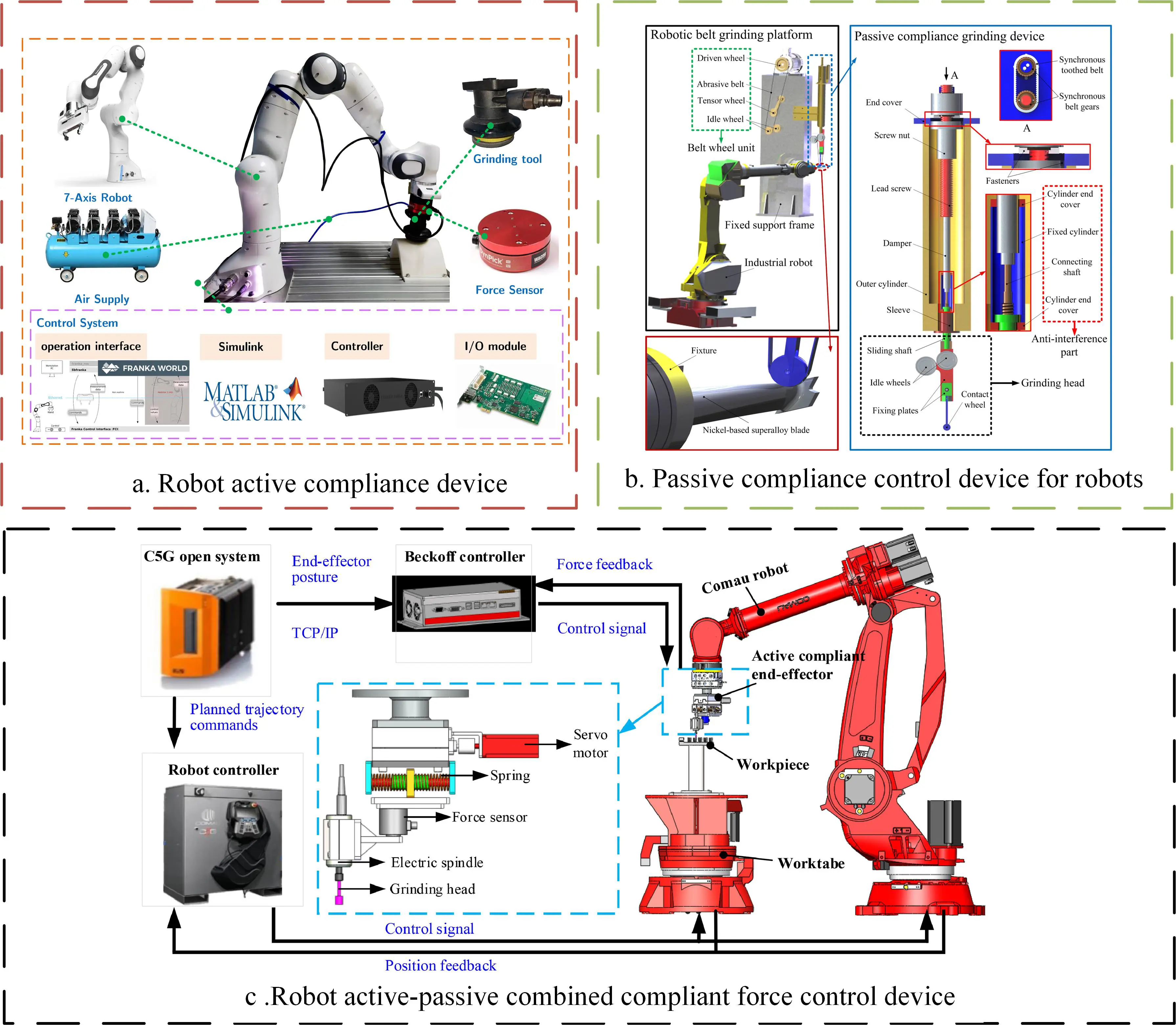
Figure 17. Robot compliance control device: (a). Robot active compliance device, (b). Passive compliance control device for robots, (c). Robot active-passive combined compliance force control device.
5.2. Active Control of Grinding Chatter
An industrial robot belongs to a chain multi-link series structure, and its system stiffness is low. When robots are used in the assembly field of aviation and aerospace, such as titanium alloy, nickel-based alloy, or composite material, because of the cutting force and disturbance produced by these difficult-to-machine materials, excited, robot machining system is easy to produce cutting chatter, which leads to the decline of machining accuracy. It even causes serious consequences such as product scrap and robot damage. Therefore, chatter monitoring during machining is the basis for ensuring machining quality.
Chatter of the robot machining system is a complex elastic dynamic phenomenon, which is mainly caused by the self-excitation of the robot machining system structure absorbing energy from the periodic cutting force in the cutting process. Robot stiffness is an important index that satisfies robot machining accuracy and performance requirements. The robot arm of the robot machining system is a mechanical structure with a multi-link series connection, and its structural characteristics lead to low overall stiffness of the robot, which is also the main factor of robot machining chatter. At present, research on the chatter phenomenon in the robot machining process is still in the initial stage at home and abroad. Pashkevich et al. [135] proposed a method to enhance the stiffness analysis of series and parallel manipulators with passive joints, introducing a nonlinear stiffness model for manipulators with passive joints and providing stability criteria for kinematic chain configuration. Özer et al. [136] studied chatter phenomena in the drilling of a two-link manipulator model. The results show that chatter phenomena can be passively controlled by spindle speed and joint stiffness changes, and flutter stability lobe diagrams under different joint stiffness are drawn. Tobias [137] proposed a mathematical theory of tool chatter. Chatter is categorised into two types based on whether the amplitude falls in the direction of the tool holder or the workpiece velocity. Research indicates that the stability of the system is influenced by factors such as workpiece velocity, workpiece material, and the geometry of the tool and holder. Furthermore, under certain conditions, variations in chip thickness may exert a stabilising effect. Pan et al. [138] studied the chatter mechanism of a milling robot system used to machine casting blanks, and established the theoretical model of cutting force and structural model. The results show that the chatter of an articulated machining robot may belong to a coupled mode, which is different from the regenerative chatter mechanism of general cutting machine tools. Hazel et al. [139] found that there is a repeated impact phenomenon between the tool and the workpiece in the robot grinding system by using a high-speed camera. After studying the machining chatter problem of the grinding robot, it is pointed out that the mechanism of regenerative chatter may be the cause of machining chatter of the grinding robot, and the stable region of the robot grinding technician is given by simulation calculation. Hao et al. [140] studied the mechanism of machining chatter in robot boring process, and thought that the chatter occurred in the whole robot boring system, not the boring bar itself, which was different from the regenerative chatter in machine tool boring. Stability optimization was carried out by increasing the pressing force between the pressure foot and the machined workpiece. The results showed that the robot may have experienced modal coupling chatter before the regenerative chatter occurred. According to the present research, the chatter types of different robot machining systems may be different, and the theoretical viewpoints of modal coupling chatter and regenerative chatter need to be verified in robot machining system cutting chatter. In addition, the theoretical model of the robot machining system cutting chatter is still to be perfected. It is necessary to carry out multidimensional vibration modal analysis based on establishing the dynamic model of robot machining system, and solve the chatter stability region by using time domain method and frequency domain method to reveal the action mechanism of system dynamic parameters such as mass matrix, stiffness matrix and damping matrix on cutting chatter under different machining parameters and robot poses, and explore the mechanism of cutting chatter.
RAFIEIAN et al. [141] studied the instability of regenerative vibration in the robot grinding process, and found that the cyclic dynamic impact in the material removal process is the main cause of regenerative vibration in the machining process. To solve the problem of machining quality degradation caused by polishing tool vibration in the engine blade polishing process, Zhu et al. [142] established the stiffness equation of a six-degree-of-freedom robot, proposed the method of extracting mold boundary line based on Virtual Reality Modeling Language (VRML) technology, optimized the feed grinding track near mold boundary, designed the feed grinding track planning and vibration optimization system of pneumatic grinding wheel, and realized the vibration suppression of robot-controlled pneumatic grinding wheel feed grinding. Jin et al. [143] by combining theoretical modeling and numerical simulation, the vibration law of belt grinding of the blade profile of an integral bladed disk is studied, and the theoretical grinding stability conditions and the optimal combination of process parameters were obtained.
Currently, flutter suppression methods mainly include passive, active, and semi-active control. Silva et al. [144] proposed a damping method to solve the flutter instability problem by using embedded piezoelectric plates connected to a passive shunt circuit in the tool holder to provide additional damping to the system. Wu et al. [145] proposed a subtractive average optimization algorithm (SABO) to optimize the key parameters of variational modal decomposition (VMD), constructed a flutter identification index based on power spectral entropy difference (Δ PSE) according to the spectral characteristics of the flutter signal, and adopted the K-means ++ algorithm to identify different flutter types. Liu et al. [146] proposed an improved empirical mode decomposition method based on a permutation entropy algorithm, which detects and eliminates abnormal signals in vibration signals. BP neural network is optimized by a genetic algorithm to establish flutter identification model. Finally, the extracted five characteristic parameters are used as feature vectors to monitor the machining state.
5.3. Optimization of Grinding Process Parameters
Process parameter optimization technology is the main means to improve the surface integrity and machining efficiency of robot polished parts, and it is also a key task of the robot automatic machining system. From the microscopic point of view, abrasive is pressed into the surface of parts by polishing pressure during the grinding process, and at the same time, relative movement occurs with the surface of parts driven by tool rotation and feed movement, and then the interaction, such as scraping and impact, occurs continuously to achieve material removal. After repeated processing a certain number of times, the final surface morphology of parts has different degrees of medium frequency waviness and high frequency roughness. According to the requirements of robot precision manufacturing, the allowable intervals of polishing pressure, tool rotation speed, tool feed, and grinding times should be limited for the stability of the grinding removal process. The prediction mechanism of surface roughness under different process parameters should be established, and the optimal efficiency planning method of robot grinding process parameters should be established, considering the constraints of surface roughness and surface waviness.
The robotic grinding system based on a process parameter optimization model, primarily comprises a robotic module, a belt grinder module, and an acoustic detection module. As shown in Figure 18, the acoustic detection module captures belt dressing sound signals via omnidirectional capacitive microphones. Utilizing a data-driven model trained with optimal pruning limit learning machines enables rapid and accurate detection and prediction of the system's machining status. By controlling process parameters such as grinding force and belt linear speed, the system achieves optimal machining quality.
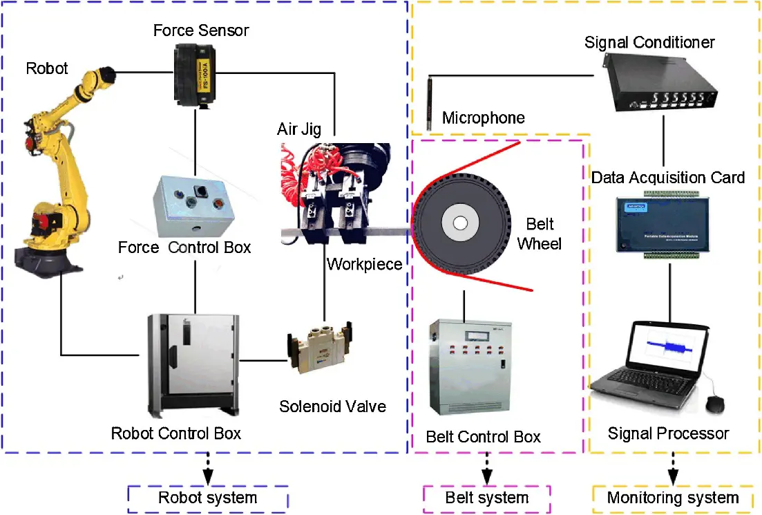
Surface waviness and surface roughness are the main indexes to measure the surface integrity after robot grinding. Establishing the correlation model between them and grinding process parameters is the premise of process parameter optimization. The polishing path distribution and polishing tool removal function profile directly affect surface waviness. The removal function can effectively evaluate the influence of process parameters on surface waviness. Existing surface roughness prediction models can be divided into three categories:
- (1)
- Based on machining theory, the roughness prediction method is used to estimate the surface roughness by numerical simulation using the micro-cutting action between abrasive particles and workpiece or the geometry of the grinding movement process.
- (2)
- Roughness prediction methods based on design of experiments (DoE) and analysis are used to predict surface roughness through DOE, experimental data processing and analysis, among which the regression analysis method, response surface method, and Taguchi experimental method are the most widely used methods.
- (3)
- Roughness prediction methods based on artificial intelligence models mainly use data mining and artificial intelligence algorithms to describe the correlation between polishing process parameters and surface roughness, and finally predict surface roughness.
The roughness prediction method based on machining theory needs geometric simulation of abrasive distribution, and also needs to consider the influence of abrasive random distribution on the material removal process, which requires high relative motion accuracy between the abrasive and part surface. Due to the influence of nonlinear error factors such as machining vibration and motion positioning error of the robot, the prediction accuracy of this method is poor in robot polishing scene, and it can only qualitatively analyze the influence of process parameters on surface roughness. At present, a lot of research has been carried out on roughness prediction methods based on experimental design and analysis, and roughness prediction methods based on artificial intelligence models in the optimization of process parameters. Khalick et al. [148] utilized neural networks (NNW) and genetic algorithms (GA) to predict grinding performance parameters and optimize machining parameters corresponding to specific grinding parameters. The effectiveness of the proposed algorithm is verified by experiments on grinding uneven surfaces. Mohsin et al. [149] analyzed the effects of different input polishing parameters on machining efficiency and torque in a robotic grinding system for circular workpieces by using Taguchi’s method and ANOVA. In the design of experiments (DOE) technique, Taguchi’s L18 array was selected to find optimized process parameters for machining efficiency (based on surface roughness) and torque. Statistical analysis of the experimental results by signal-to-noise ratio and ANOVA (95% confidence level) confirms that grinding force and tool speed are the most important factors affecting the grinding efficiency of the system. Pan et al. [150] proposed a prediction model of polished workpiece surface based on the XGBoost algorithm, and verified the accuracy of the model by experiments. The experimental results show that the maximum absolute error between the predicted roughness and the experimental roughness is 0.035 μm, and the maximum relative error is less than 9%. Huai et al. [151] proposed a grinding process parameter optimization method based on a neural network and genetic algorithm for the autonomous selection and optimization of process parameters of the robot grinding system. The complex nonlinear problem among process parameters was solved by using the workpiece surface roughness prediction model based on artificial neural network. The genetic algorithm is used to optimize all process parameters globally to solve the double objective optimization problem of machining quality and efficiency and to obtain the optimal combination of process parameters. Rao et al. [152] proposed a new method based on frequency domain features to directly connect spatial process parameters and frequency domain evaluation indicators for manufacturing free-form surfaces with nano-precision for polished car covers. Bessel functions and single pulse convolution are introduced to establish the model. A self-designed polishing robot optimizes polishing parameters. The surface roughness is improved from 5.13 nm to 2.36 nm.
The stability of the robot grinding process and the final quality of the parts surface are affected not only by machining process parameters, but also by time-varying abrasive wear, surface topography error before machining, and lubrication conditions of cutting fluid [153,154,155]. Abrasive wear process is a kind of abrasive self-sharpening process, abrasive will undergo wear, fracture, shedding a series of changes, more prominent height abrasive will be preferentially damaged by wear, with the gradual progress of the machining process, protruding height of the abrasive will gradually participate in the grinding process to maintain the stability of the machining tool, gradual change in machining removal capacity will change with the time of abrasive wear into the polishing removal model, can effectively improve the accuracy and uniformity of surface material removal [156]. Wan et al. [157] analyzed the generation mechanism of the grinding pad to quantitatively predict the wear amount of the grinding pad under different process parameters, so that TIF error caused by grinding pad wear can be compensated. Experimental results show that the proposed model can reliably predict the pad shape and TIF after different wear times, and the forming quality and convergence rate of robot grinding can be improved significantly. Gao et al. [158] proposed a new CFRP grinding method using multi-angle two-dimensional ultrasonic vibration energized nano-lubricant MQL to develop a steady-state model of forces under different ultrasonic and lubricating cooling conditions to optimize and adjust machining strategies and parameters. Liu et al. [159] analyzed the dynamic mechanism of atomized droplet film formation, revealing the influence of normal and tangential momentum sources generated by gas impact disturbance flow and droplet impact steady flow on the driving effect of liquid film flow. Effectively improve the heat transfer and lubrication performance of oil film in grinding area. Zheng et al. [160] proposed a method for optimizing robot polishing parameters considering time-varying wear. This greatly reduces the amount of experimental data required for the original regression model. Based on the prediction model, a genetic algorithm is used to optimize polishing parameters to achieve better machining quality and lower energy consumption.
Related research shows that surface roughness and cutting signal characteristic parameters such as force, heat and vibration tend to be stable gradually with the increase of machining times under the same abrasive grain size in robot grinding process, and there is a mapping relationship between machined surface roughness and cutting signal characteristic parameters [161]. Segreto et al. [162] evaluated the surface roughness of robot-assisted polished steel bars using an acoustic emission sensor monitoring system. After sensor signal pretreatment, a feature extraction program is applied to the processed AE signal and input into a pattern recognition paradigm to identify the correlation between process-generated AE and polished workpiece surface roughness. Bissacco et al. [163] propose a monitoring and control strategy based on a multi-sensory robotic arm for automatic detection of process endpoints, as well as characterization of the total surface area of the machine and identification of local defects, measuring acoustic emission signals and grinding forces, and surface roughness up to 10nm when robot-assisted polishing (RAP) rotationally symmetric and free-form parts. Zhu et al. [164] proposed a method for tool state recognition in the robot machining process based on neural ordinary differential equation (Neural ODE) and BP neural network optimization based on genetic algorithm (BP-GA). Numerical experiments show that the accuracy of the model recognition is 96.55%.
To sum up, the robot grinding process parameters directly impact the surface quality indicators such as surface waviness and surface roughness. The existing research establishes the correlation model between grinding process parameters and material removal rate and surface roughness based on experimental design, and then guarantees efficient and precise robot grinding by optimizing the processing process parameters. In addition, combined with sensor technology, a large amount of research on machining tool wear, real-time online evaluation of surface roughness, and other issues has been carried out, which has laid the foundation for robotic automatic precision grinding.
6. Conclusions and Future Perspectives
6.1. Conclusions
As systematically analyzed throughout this review, leveraging the flexibility, precision and programmability of industrial robots, combined with specialized grinding tools and sensing technology, robotic grinding systems have demonstrated significant potential as advanced automation solutions for complex workpiece finishing. The primary purpose of this study was to dissect the key technological pillars enabling high-precision robotic grinding, specifically focusing on motion control, compliance force control, and process optimization, as a means to address the critical challenges of machining accuracy, force stability, and surface quality consistency. Combined with advanced measurement technology, a flexible robotic grinding system can become an effective means of precision grinding, improving flexible high-precision machining ability and promoting the upgrading of the national manufacturing equipment industry. Through summary research, it is found that the key technologies of robot grinding are mainly embodied in three aspects:
- (1)
-
From the perspective of robot kinematics, existing research has significantly improved the motion accuracy and path smoothness of robots in complex surface grinding through high-precision calibration compensation, dexterous workspace analysis, and advanced trajectory planning algorithms. By integrating workpiece geometric characteristics and requirements for uniform material removal, path planning strategies have been optimized, providing a kinematic foundation for robotic precision grinding.
- (2)
- From the perspective of force control in robotic grinding systems, active and passive compliance control strategies have become effective means to address the insufficient stiffness of robots, suppress machining chatter, and maintain stable grinding forces. These strategies enhance the adaptability of robots to complex surfaces and difficult-to-machine materials, improve system robustness and machining consistency, and strengthen the flexibility and capability of robotic systems to handle multi-variety and challenging material processing tasks.
- (3)
- From the perspective of robotic grinding process optimization, the establishment of mapping models between process parameters and surface quality indicators, combined with experimental design and intelligent algorithms for parameter optimization, effectively enhances grinding efficiency and surface consistency. The introduction of online monitoring technology further improves process controllability and adaptability, ensuring process stability and controlled surface quality, thereby providing theoretical support for the intelligent development of robotic grinding systems.
6.2. Future Perspectives
Although significant progress has been made in robotic grinding technology, several core challenges remain in fully replacing traditional CNC machine tools for ultra-precision machining applications. To further enhance the capabilities and application scope of robotic grinding systems, more systematic and cutting-edge explorations can be conducted in the following directions:
- (1)
- Intelligent Process Decision-Making and Quality Prediction
Building upon existing research on roughness prediction models and material removal simulation technology, future efforts will focus on developing self-optimizing intelligent decision systems. Such systems will integrate real-time online monitoring data with a process knowledge base to enable dynamic optimization and adaptive adjustment of grinding parameters, significantly improving consistency and reliability in machining quality. This will achieve real-time self-optimization of grinding parameters and facilitate the construction of a digital twin-driven grinding process optimization system, allowing dynamic prediction and fine-tuning of process parameters through virtual mapping of the physical system. - (2)
- High-Dynamic Force Control and Vibration Suppression
Current robotic systems exhibit limited stiffness, resulting in force-tracking lag and a tendency for vibration when processing surfaces with abrupt curvature changes or difficult-to-machine materials. Future work should develop adaptive variable impedance control schemes incorporating disturbance observers to compensate for system dynamics and external disturbances. Additionally, exploring online chatter recognition and suppression technology based on multi-modal sensing—integrating force, acoustic, and vibration data—will enable real-time vibration control. - (3)
- Modular Integration and Closed-Loop Manufacturing
Current robotic system integration remains costly and lacks reconfigurability, making it difficult to adapt to low-volume, high-variety production demands. Future grinding systems should evolve toward modular, reconfigurable, and highly integrated architectures to enhance system flexibility and intelligence. This requires deeply integrated multi-functional end-effectors as processing execution units and high-precision in-situ inspection technology as sensing units. The ultimate goal is to establish a seamlessly integrated closed-loop smart manufacturing unit encompassing “machining—real-time in-situ inspection—intelligent correction”. Furthermore, developing an open-source robotic grinding algorithm framework that encapsulates core functions such as calibration, path planning, and force control will reduce system integration barriers.
The future development of robotic grinding systems will rely on deep integration with artificial intelligence technologies. By focusing on the above research directions, robotic grinding systems are expected to overcome existing bottlenecks such as low machining accuracy, significant grinding force fluctuations, and poor surface quality consistency. This will provide economical and efficient precision machining solutions for high-value fields such as aerospace and energy equipment.
Statement of the Use of Generative Al and Al-Assisted Technologies in the Writing Process
During the preparation of this manuscript, the authors used embedded AI in Grammerly in order to check grammar. After using this tool, the authors reviewed and edited the content as needed and take full responsibility for the content of the published article.
Author Contributions
Conceptualization, Z.L. and S.Q.; Methodology, Y.G., D.C. and P.Y.; Investigation, Y.S.; Data Curation, Y.S. and X.X.; Writing—Original Draft Preparation, Z.L.; Writing—Review & Editing, Z.L. and S.Q.; Funding Acquisition, S.Q.
Ethics Statement
Not applicable.
Informed Consent Statement
Not applicable.
Data Availability Statement
The data that support the findings of this study are available from the corresponding author upon reasonable request.
Funding
This study was supported by Key Laboratory of High-effciency and Clean Mechanical Manufacture at Shandong University, Ministry of Education, the National Natural Science Foundation of China (No. 52305484, No. 52305475, and No. U23A20632), the China Postdoctoral Science Foundation (No. 2024M761876), the National Key Research and Development Program of China (No. 2023YFC2413301), the Taishan Scholars Program (No. tsqn202408242), the Shandong Provincial Natural Science Foundation (No. ZR2022QE053 and No. ZR2022QE159), the Guangdong Basic and Applied Basic Research Foundation (No. 2022A1515111124), the Major Scientific and Technological Innovation Project of Shandong Province (No. 2023CXGC010207), the Major Basic Research of Shandong Provincial Natural Science Foundation (No. ZR2023ZD34), and the talent research project for the pilot project of integrating science, education, and industries of Qilu University of Technology (Shandong Academy of Sciences) (2024RCKY009).
Declaration of Competing Interest
The authors declare that they have no known competing financial interests or personal relationships that could have appeared to influence the work reported in this paper.
References
-
Zhao J. Application and development of industrial robot technology in intelligent manufacturing. Autom. Appl. 2023, 64, 16–18. [Google Scholar]
-
Dai HC, Sun DN, Zhao WB. A review of the development and application of industrial robot technology. New Ind. 2021, 5–6. [Google Scholar]
-
Yao Q. “Made in China 2025” The impact of intelligent manufacturing on economic growth under the policy of technological innovation. China Mark. 2022, 5. [Google Scholar]
-
Deng Z, Qu X. Industrial robot development and manufacturing transformation and upgrading--based on the survey of industrial robot use in China. Reform 2021, 25–37. [Google Scholar]
-
Zhang Q, Han LL, Xu F, Jia K, and Zou F. Research on Force/Position Hybrid Control Strategy Based on Grinding Robot. Chem. Autom. Instrum. 2012, 7, 4. [Google Scholar]
-
Qu S, Yang Y, Yao P, Li L, Sun Y, Chu DK. Fiber reinforced ceramic matrix composites: from the controlled fabrication to precision machining. Int. J. Extrem. Manuf. 2025, 7, 062004. [Google Scholar]
-
Bu CW. Control Research on Wind Turbine Blade Grinding Robots. Master’s Thesis, Harbin Engineering University, Harbin, China, 2013. [Google Scholar]
-
Li L, Ye T, Tan M, Chen XJ. Current situation and future of mobile robot technology. Robotics 2002, 24, 475–480. [Google Scholar]
-
Zhu D, Feng X, Xu X, Yang ZY, Li WL, Yan SJ, Ding H. Robotic grinding of complex components: A step towards efficient and intelligent machining—Challenges, solutions, and applications. Robot. Comput. -Integr. Manuf. 2020, 65, 101908. [Google Scholar]
-
Ding X, Qiao J, Liu N, Yang Z, Zhang R. Robotic grinding based on point cloud data: developments, applications, challenges, and key technologies. Int. J. Adv. Manuf. Technol. 2024, 131, 3351–3371. [Google Scholar]
-
Villagrossi E, Cenati C, Pedrocchi N, Beschi M, Molinari Tosatti L. Flexible robot-based cast iron deburring cell for small batch production using single-point laser sensor. Int. J. Adv. Manuf. Technol. 2017, 92, 1425–1438. [Google Scholar]
-
Pappachan BK, Caesarendra W, Tjahjowidodo T, Wijaya T. Frequency Domain Analysis of Sensor Data for Event Classification in Real-Time Robot Assisted Deburring. Sensors 2017, 17, 1247. [Google Scholar]
-
Eder SJ, Cihak-Bayr U, Pauschitz A. Nanotribological simulations of multi-grit polishing and grinding. Wear 2015, 340–341, 25–30. [Google Scholar]
-
Tang J, Wang T, Yan ZQ, Wang LW. Design and Analysis of the End-Effector of the Flexible Polishing Robot. Key Eng. Mater. 2016, 693, 58–63. [Google Scholar]
-
Huang Y, Xiao G, Zou L. Research Status and Development Trend of Robot Precision Abrasive Belt Grinding for Aeroengine Blades. J. Aeronaut. 2019, 40, 53–72. [Google Scholar]
-
Xiao G, Huang Y, Wang J. Path planning method for longitudinal micromarks on blisk root-fillet with belt grinding. Int. J. Adv. Manuf. Technol. 2018, 95, 797–810. [Google Scholar]
-
Liang W, Song YX, Lv HB, Jia PF, Gan ZG, Qi LZ. A Novel Control Method for Robotic Belt Grinding Based on SVM and PSO Algorithm. In Proceedings of the 2010 International Conference on Intelligent Computation Technology and Automation, Changsha, China, 11–12 May 2010; pp. 258–261. [Google Scholar]
-
Quintana G, Ciurana J. Chatter in machining processes: A review. Int. J. Mach. Tools Manuf. 2011, 51, 363–376. [Google Scholar]
-
Yu D. Development status and trend of industrial robots at home and abroad. Public Electr. 2017, 32, 20–21. [Google Scholar]
-
Qi M, Li X, Gao B. Analysis on the Present Situation and Trend of Robot Technology Development in Foreign Aviation Field. Aerosp. Manuf. Technol. 2018, 61, 97–101. [Google Scholar]
-
Ji W, Wang L. Industrial robotic machining: A review. Int. J. Adv. Manuf. Technol. 2019, 103, 1239–1255. [Google Scholar]
-
Wu D. Research on Development and Prospect of Industrial Robots in China. Appl. Mech. Mater. 2014, 536–537, 1717–1720. [Google Scholar]
-
Whitney DE, Edsall AC, Todtenkopf AB, Kurfess T R, Tate A R. Development and Control of an Automated Robotic Weld Bead Grinding System. J. Dyn. Syst. Meas. Control. 1990, 112, 166–176. [Google Scholar]
-
Whitney DE, Tung ED. Robot Grinding and Finishing of Cast Iron Stamping Dies. J. Dyn.Syst.Meas. Control. 1992, 114, 132–140. [Google Scholar]
-
Kazerooni H. Automated robotic deburring using impedance control. IEEE Control. Syst. Mag. 1988, 8, 21–25. [Google Scholar]
-
Van Brussel H, Persoons W. Robotic Deburring of Small Series of Castings. CIRP Ann. 1996, 45, 405–410. [Google Scholar]
-
Tian F, Lv C, Li Z, Liu GB. Modeling and control of robotic automatic polishing for curved surfaces. CIRP J. Manuf. Sci. Technol. 2016, 14, 55–64. [Google Scholar]
-
Persoons W, Vanherck P. A Process Model for Robotic Cup Grinding. CIRP Ann. —Manuf. Technol. 1996, 45, 319–325. [Google Scholar]
-
KUKA. KUKA robot enables automatic removal of casting burrs. Met. Process. Hot Process. 2018, 11. [Google Scholar]
-
Márquez JJ, Pérez JM, Rı́os J, Rı́os J, Vizán A. Process modeling for robotic polishing. J. Mater. Process. Technol. 2005, 159, 69–82. [Google Scholar]
-
Nagata F, Kusumoto Y, Watanabe K, Tsuda K, Yasuda K, Yokoyama K, et al. Polishing robot for PET bottle molds using a learning-based hybrid position/force controller. In Proceedings of the 2004 5th Asian Control Conference (IEEE Cat. No.04EX904), Melbourne, VIC, Australia, 20–23 July 2004. [Google Scholar]
-
Xiao G, Huang Y, Yin J. An integrated polishing method for compressor blade surfaces. Int. J. Adv. Manuf. Technol. 2017, 88, 1723–1733. [Google Scholar]
-
Whitton S. Adaptive robot grinding improves turbine blade repair. Ind. Robot. Int. J. 2003, 30, 1–6. [Google Scholar]
-
Sun Y, Giblin DJ, Kazerounian K. Accurate robotic belt grinding of workpieces with complex geometries using relative calibration techniques. Robot. Comput. -Integr. Manuf. 2009, 25, 204–210. [Google Scholar]
-
Husmann S, Stemmler S, Hähnel S, Vogelgesang S, Abel D, Bergs T. Model Predictive Force Control in Grinding based on a Lightweight Robot. IFAC-PapersOnLine 2019, 52, 1779–1784. [Google Scholar]
-
Feng Y, Xu D, Wang Y. Development of HITDM-Ⅰ grinding robot. Robotics 1993, 15, 38–42. [Google Scholar]
-
Zhan J, Zhao J, Zhu P. Precision machining system of robot ultrasonic polishing free-form surface. China Mech. Eng. 2000, 11, 3. [Google Scholar]
-
Huang Y, Xiao G, Zou L. Research status and development trend of integral bladed disk polishing technology. J. Aeronaut. 2016, 37, 2045. [Google Scholar]
-
Qi L, Gan Z, Sun Y, Tang Q, Yun C, Wu SH. Robotic grinding and polishing system for complex surface workpiece. Mech. Des. 2011, 28, 38–41. [Google Scholar]
-
Mao Y, Zhao H, Zhao X, Ding H. Trajectory and Force Generation with Multi-constraints for Robotic Belt Grinding. In Intelligent Robotics and Applications, Proceedings of the International Conference on Intelligent Robotics and Applications 2017; Springer International Publishing: Cham, Switzerland, 2017; pp. 14–23. [Google Scholar]
-
Ren X. Research on Key Technology of Robot Abrasive Belt Grinding for Aeroengine Blades. Master’s thesis, Chongqing University, Chongqing, China, 2017. [Google Scholar]
-
Wang P. Research on Key Technology of Robot Grinding and Polishing System for Engine Blades. Master’s thesis, Nanjing University of Aeronautics and Astronautics, Nanjing, China, 2025. [Google Scholar]
-
Gong Y, Zhao X, Zhang W,Tang BJ. Influence factors of single abrasive grain material removal in robot belt grinding. J. Northeast. Univ. (Nat. Sci. Ed.) 2023, 44, 1285–1291. [Google Scholar]
-
Shi X, Li M, Dong Y, Dong YH, Feng SY. Research on Surface Tracking and Constant Force Control of a Grinding Robot. Sensors 2023, 23, 4702. [Google Scholar]
-
Lakshminarayanan S, Kana S, Mohan DM, Manyar OM. An adaptive framework for robotic polishing based on impedance control. Int. J. Adv. Manuf. Technol. 2021, 112, 401–417. [Google Scholar]
-
Zhang HY, Li L,Zhao JB, Zhao JC. The hybrid force/position anti-disturbance control strategy for robot abrasive belt grinding of aviation blade base on fuzzy PID control. Int. J. Adv. Manuf. Technol. 2021, 114, 3645–3656. [Google Scholar]
-
Zou L, Liu X, Ren X, Huang Y. Investigation of robotic abrasive belt grinding methods used for precision machining of aluminum blades. Int. J. Adv. Manuf. Technol. 2020, 108, 3267–3278. [Google Scholar]
-
Zhang T, Yu Y, Zou Y. An Adaptive Sliding-Mode Iterative Constant-force Control Method for Robotic Belt Grinding Based on a One-Dimensional Force Sensor. Sensors 2019, 19, 1635. [Google Scholar]
-
Zhang T, Wu S, Cai C. Constant Force Control Method for Robotic Disk Grinding Based on Floating Platform. J. Shanghai Jiaotong Univ. 2020, 54, 515–523. [Google Scholar]
-
Feng D, Sun Y, Du H. Investigations on the automatic precision polishing of curved surfaces using a five-axis machining centre. Int. J. Adv. Manuf. Technol. 2014, 72, 1625–1637. [Google Scholar]
-
Yang MY, Lee HC. Local material removal mechanism considering curvature effect in the polishing process of the small aspherical lens die. J. Mater. Process. Technol. 2001, 116, 298–304. [Google Scholar]
-
Fan C, Zhao J, Zhang L, Zhou WS, Sun L. Local material removal model considering the tool posture in deterministic polishing. Proc. Inst. Mech. Eng. Part C J. Mech. Eng. Sci. 2016, 230, 2660–2675. [Google Scholar]
-
Wu X, Huang Z, Wan Y, Liu HT, Chen X. A Novel Force-Controlled Spherical Polishing Tool Combined with Self-Rotation and Co-Rotation Motion. IEEE Access 2020, 8, 108191–108200. [Google Scholar]
-
Lee H, Kim J, Kang H. Airbag tool polishing for aspherical glass lens molds. J. Mech. Sci. Technol. 2010, 24, 153–158. [Google Scholar]
-
Ge J, Deng Z, Cao D, Li ZY, Lv L, Liu W, Nie JX. Study on modelling simulation and distribution characteristics of residual stress during robotic weld end grinding of high strength modulated steel. J. Manuf. Process. 2023, 108, 98–113. [Google Scholar]
-
Zhang J. Flexible Contact Mechanics Behavior and Experimental Study of Flap Wheel Polishing for Investment-Cast Blades by Robotic Manipulation. Ph.D. thesis, Taiyuan University of Technology, Taiyuan, China, 2025. [Google Scholar]
-
Cen L, Melkote SN, Castle J, Castle J, Appelman H. A Wireless Force-Sensing and Model-Based Approach for Enhancement of Machining Accuracy in Robotic Milling. IEEE/ASME Trans. Mechatron. 2016, 21, 2227–2235. [Google Scholar]
-
Thomson W. Theory of Vibration with Applications; CRC Press: London, UK, 2018. [Google Scholar]
-
Lipkin H, Patterson T. Generalized center of compliance and stiffness. In Proceedings of the 1992 IEEE International Conference on Robotics and Automation, Nice, France, 12–14 May 1992; pp. 1251–1256 Volume 2. [Google Scholar]
-
Li M, Wu H, Handroos H. Static stiffness modeling of a novel hybrid redundant robot machine. Fusion Eng. Des. 2011, 86, 1838–1842. [Google Scholar]
-
Shneor Y, Portman VT. Stiffness of 5-axis machines with serial, parallel, and hybrid kinematics: Evaluation and comparison. CIRP Ann. 2010, 59, 409–412. [Google Scholar]
-
Alici G, Shirinzadeh B. Enhanced stiffness modeling, identification and characterization for robot manipulators. IEEE Trans. Robot. 2005, 21, 554–564. [Google Scholar]
-
Abele E, Weigold M, Rothenbücher S. Modeling and Identification of an Industrial Robot for Machining Applications. CIRP Ann. 2007, 56, 387–390. [Google Scholar]
-
Zhou J, Nguyen HN, Kang HJ. Simultaneous identification of joint compliance and kinematic parameters of industrial robots. Int. J. Precis. Eng. Manuf. 2014, 15, 2257–2264. [Google Scholar]
-
Slavkovic NR, Milutinovic DS, Glavonjic MM. A method for off-line compensation of cutting force-induced errors in robotic machining by tool path modification. Int. J. Adv. Manuf. Technol. 2014, 70, 2083–2096. [Google Scholar]
-
Klimchik A, Wu Y, Caro S, Dumas C, Furet B, Pashkevich A. Modelling of the gravity compensators in robotic manufacturing cells. IFAC Proc. Vol. 2013, 46, 790–795. [Google Scholar]
-
Kurazume R, Hasegawa T. A new index of serial-link manipulator performance combining dynamic manipulability and manipulating force ellipsoids. IEEE Trans. Robot. 2006, 22, 1022–1028. [Google Scholar]
-
Hardeman T, Aarts R, Jonker B. Modelling and Identification of Robots with Joint and Drive Flexibilities. In IUTAM Symposium on Vibration Control of Nonlinear Mechanisms and Structures, Proceedings of the IUTAM Symposium Held in Munich, Germany, 18–22 July 2005; Springer: Dordrecht, The Netherlands, 2005; pp. 173–182. [Google Scholar]
-
Slamani M, Gauthier S, Chatelain JF. A study of the combined effects of machining parameters on cutting force components during high speed robotic trimming of CFRPs. Measurement 2015, 59, 268–283. [Google Scholar]
-
Vosniakos GC, Matsas E. Improving feasibility of robotic milling through robot placement optimisation. Robot. Comput. -Integr. Manuf. 2010, 26, 517–525. [Google Scholar]
-
Zargarbashi SHH, Khan W, Angeles J. Posture optimization in robot-assisted machining operations. Mech. Mach. Theory 2012, 51, 74–86. [Google Scholar]
-
Matsuoka SI, Shimizu K, Yamazaki N, Oki Y. High-speed end milling of an articulated robot and its characteristics. J. Mater. Process. Technol. 1999, 95, 83–89. [Google Scholar]
-
Rafieian F, Liu Z, Hazel B. Dynamic model and modal testing for vibration analysis of robotic grinding process with a 6DOF flexible-joint manipulator. In Proceedings of the 2009 International Conference on Mechatronics and Automation, Changchun, China, 9–12 August 2009; pp. 2793–2798. [Google Scholar]
-
Bisu C, Cherif M, Gerard A, K'nevez JY. Dynamic behavior analysis for a six axis industrial machining robot. Adv. Mater. Res. 2012, 423, 65–76. [Google Scholar]
-
Mejri S, Gagnol V, Le TP, Sabourin L, Ray P, Paultre P. Dynamic characterization of machining robot and stability analysis. Int. J. Adv. Manuf. Technol. 2016, 82, 351–359. [Google Scholar]
-
Klimchik A, Chablat D, Pashkevich A. Static stability of manipulator configuration: Influence of the external loading. Eur. J. Mech. —A/Solids 2015, 51, 193–203. [Google Scholar]
-
Albu-Schaffer A, Hirzinger G. Cartesian impedance control techniques for torque controlled light-weight robots. In Proceedings of the 2002 IEEE International Conference on Robotics and Automation (Cat. No.02CH37292), Washington, DC, USA, 11–15 May 2002; Volume 1, pp. 657–663. [Google Scholar]
-
Andres J, Gracia L, Tornero J. Implementation and testing of a CAM postprocessor for an industrial redundant workcell with evaluation of several fuzzified Redundancy Resolution Schemes. Robot. Comput. -Integr. Manuf. 2012, 28, 265–274. [Google Scholar]
-
Pei JF, Cheng JS. Optimization of Force Directional Manipulability of Dexterous Robot Hand. In Proceedings of the Engineering Design and Manufacturing Informatization 2010 International Conference on System Science, Yichang, China, 12–14 November 2010; Volume 1, pp. 226–229. [Google Scholar]
-
Ajoudani A, Tsagarakis NG, Bicchi A. On the role of robot configuration in Cartesian stiffness control. In Proceedings of the 2015 IEEE International Conference on Robotics and Automation (ICRA), Seattle, WA, USA, 26–30 May 2015; pp. 1010–1016. [Google Scholar]
-
Vahrenkamp N, Asfour T. Representing the robot’s workspace through constrained manipulability analysis. Auton. Robot. 2015, 38, 17–30. [Google Scholar]
-
Roberts RG. The dexterity and singularities of an underactuated robot. J. Robot. Syst. 2001, 18, 159–169. [Google Scholar]
-
Park FC, Brockett RW. Kinematic Dexterity of Robotic Mechanisms. Int. J. Robot. Res. 1994, 13, 1–15. [Google Scholar]
-
Tchoń K, Zadarnowska K. Kinematic dexterity of mobile manipulators: an endogenous configuration space approach. Robotica 2003, 21, 521–530. [Google Scholar]
-
Gao Z, Lan X, Bian Y. Structural Dimension Optimization of Robotic Belt Grinding System for Grinding Workpieces with Complex Shaped Surfaces Based on Dexterity Grinding Space. J. Aviat. China Engl. Ed. 2011, 24, 346–354. [Google Scholar]
-
Li W, Song P. A modified ICP algorithm based on dynamic adjustment factor for registration of point cloud and CAD model. Pattern Recognit. Lett. 2015, 65, 88–94. [Google Scholar]
-
Gong C, Yuan J, Ni J. Nongeometric error identification and compensation for robotic system by inverse calibration. Int. J. Mach. Tools Manuf. 2000, 40, 2119–2137. [Google Scholar]
-
Nubiola A, Bonev IA. Absolute calibration of an ABB IRB 1600 robot using a laser tracker. Robot. Comput. -Integr. Manuf. 2013, 29, 236–245. [Google Scholar]
-
Xu X, Zhu D, Zhang H, Yan SJ, Ding H. TCP-based calibration in robot-assisted belt grinding of aero-engine blades using scanner measurements. Int. J. Adv. Manuf. Technol. 2017, 90, 635–647. [Google Scholar]
-
Li W L, Xie H, Zhang G, Yan SJ, Yin Z. Hand–Eye Calibration in Visually-Guided Robot Grinding. IEEE Trans. Cybern. 2016, 46, 2634–2642. [Google Scholar]
-
Zhang D, Yun C, Zhang L. Fixture Optimization for Robotic Belt Grinding System. Appl. Mech. Mater. 2011, 121–126, 2030–2034. [Google Scholar]
-
Gao G, Liu F, San H, Wu X, Wang W. Hybrid Optimal Kinematic Parameter Identification for an Industrial Robot Based on BPNN-PSO. Complexity 2018, 2018, 4258676. [Google Scholar]
-
Gao G, Sun G, Na J, Guo Y, Wu X. Structural parameter identification for 6 DOF industrial robots. Mech. Syst. Signal Process. 2018, 113, 145–155. [Google Scholar]
-
Klimchik A, Furet B, Caro S, Pashkevich A. Identification of the manipulator stiffness model parameters in industrial environment. Mech. Mach. Theory 2015, 90, 1–22. [Google Scholar]
-
Nubiola A, Bonev IA. Absolute robot calibration with a single telescoping ballbar. Precis. Eng. 2014, 38, 472–480. [Google Scholar]
-
Guo Y, Yin S, Ren Y, Zhu JG, Yang S, Ye SH. A multilevel calibration technique for an industrial robot with parallelogram mechanism. Precis. Eng. 2015, 40, 261–272. [Google Scholar]
-
Zhang T. Weighted Hand-eye Calibration Algorithm for Robot Grinding. J. Mech. Eng. 2018, 54, 142. [Google Scholar]
-
Deng Y, Hou X, Li B, Wang J, Zhang Y. A Novel Positioning Accuracy Improvement Method for Polishing Robot Based on Levenberg–Marquardt and Opposition-based Learning Squirrel Search Algorithm. J. Intell. Robot. Syst. 2023, 110, 8. [Google Scholar]
-
Wang W, Yun C. A Path Planning Method for Robotic Belt Surface Grinding. Chin. J. Aeronaut. 2011, 24, 520–526. [Google Scholar]
-
Wan S, Zhang X, Xu M, Wang W, Jiang XQ. Region-adaptive path planning for precision optical polishing with industrial robots. Opt. Express 2018, 26, 23782. [Google Scholar]
-
Gao X, Mu Y, Gao Y. Optimal trajectory planning for robotic manipulators using improved teaching-learning-based optimization algorithm. Ind. Robot. Int. J. 2016, 43, 308–316. [Google Scholar]
-
Zhang T, Su J. Collision-free planning algorithm of motion path for the robot belt grinding system. Int. J. Adv. Robot. Syst. 2018, 15, 172988141879377. [Google Scholar]
-
Ng WX, Chan HK, Teo WK, Chen IM. Programming a Robot for Conformance Grinding of Complex Shapes by Capturing the Tacit Knowledge of a Skilled Operator. IEEE Trans. Autom. Sci. Eng. 2017, 14, 1020–1030. [Google Scholar]
-
Kabir AM, Kaipa KN, Marvel J, Gupta SK. Automated Planning for Robotic Cleaning Using Multiple Setups and Oscillatory Tool Motions. IEEE Trans. Autom. Sci. Eng. 2017, 14, 1364–1377. [Google Scholar]
-
Kharidege A, Ting DT, Yajun Z. A practical approach for automated polishing system of free-form surface path generation based on industrial arm robot. Int. J. Adv. Manuf. Technol. 2017, 93, 3921–3934. [Google Scholar]
-
Chen S, Zhang T, Shao M. Interpolation optimization for robotic grinding with velocity constraints. Adv. Mech. Eng. 2017, 9, 168781401770870. [Google Scholar]
-
Qi RL, Ren K, Zhu G, Zhao JB. Complex Surface Robot Adaptive Grinding Planning and Steady Posture Tracking. J. Mech. Eng. 2025, 1–14. Available online: https://link.cnki.net/urlid/11.2187.TH.20250703.1455.049 (accessed on 21 September 2025). [Google Scholar]
-
Mao W, Pan T, Li C, Xu J. Attitude planning of robot grinding tool based on spherical linear interpolation. Mach. Tools Hydraul. 2023, 51, 6–9. [Google Scholar]
-
Han Y, Wang C, Zhang H, Yu M, Chang X, Dong J, et al. Adaptive polishing path optimization for free-form uniform polishing based on footprint evolution. Int. J. Adv. Manuf. Technol. 2024, 130, 4311–4324. [Google Scholar]
-
Wahballa H, Duan J, Wang W, Dai Z. Experimental Study of Robotic Polishing Process for Complex Violin Surface. Machines 2023, 11, 147. [Google Scholar]
-
Gong L, Fan C, Shen Z, Chen Z, Zhang L. Research on discretization algorithm of free-form surface for robotic polishing. J. Manuf. Process. 2023, 92, 350–370. [Google Scholar]
-
Liu Z, Li R, Zhao L, Xia Y, Qin Z, Zhu K. Automatic joint motion planning of 9-DOF robot based on redundancy optimization for wheel hub polishing. Robot. Comput. Integr. Manuf. Int. J. Manuf. Prod. Process Dev. 2023, 81, 102500. [Google Scholar]
-
Deng Y, Hou X, Li B, Wang J, Zhang Y. Review on mid-spatial frequency error suppression in optical components manufacturing. Int. J. Adv. Manuf. Technol. 2023, 126, 4827–4847. [Google Scholar]
-
Wang QH, Fang XL, Xie HL, Li JR, Liao Zhao Y. Rapid prediction of multi-directionality of polished surface topography based on angular spectrum. Int. J. Adv. Manuf. Technol. 2022, 122, 2871–2886. [Google Scholar]
-
Xiao M, Ding Y, Yang G. A Model-Based Trajectory Planning Method for Robotic Polishing of Complex Surfaces. IEEE Trans. Autom. Sci. Eng. 2022, 19, 2890–2903. [Google Scholar]
-
Xu CY, Li JR, Liang YJ, Wang QH, Zhou XF. Trochoidal toolpath for the pad-polishing of freeform surfaces with global control of material removal distribution Archimedean spiral toolpath para la pad-polishing de la freeform surfaces de la global control de la material removal distribution. J. Manuf. Syst. 2019, 51, 1–16. [Google Scholar]
-
Liang X, Cai Z, Zeng C, Mu ZX, Li ZF, Yang F, et al. A robotic polishing trajectory planning method for TBCs of aero-engine turbine blade using measured point cloud. Ind. Robot. Int. J. Robot. Res. Appl. 2023, 50, 275–286. [Google Scholar]
-
Tafuro A, Ghalloub C, Zanchettin AM, Rocco P. Autonomous robotic polishing of free-form poly-surfaces. Procedia Comput. Sci. 2024, 232, 2488–2497. [Google Scholar]
-
Zhang WH, Cai ZH, Chen TY, Wang Xin Y, Qu DB, Ma ZH. Correction to: A Path Planning Method for Polishing Thermal Barrier Coatings on the Surface of Aero-Engine Blades Based on Point Cloud Slicing. J. Therm. Spray Technol. 2024, 33, 1232–1232. [Google Scholar]
-
Daxian HA, Wei WA, Qilong WA, Chao YU. Application and development trend of robot in composite material processing field. J. Mech. Eng. 2019, 55, 1–17. [Google Scholar]
-
Jia L. Research on Trajectory Tracking and Compliance Control Methods and Applications of Polishing Robot. Ph.D. thesis, Hunan University, Changsha, China, 2021. [Google Scholar]
-
Zhou B, Song F, Liu Y, Fang F, Gan YH. Robust sliding mode impedance control of manipulators for complex force-controlled operations. Nonlinear Dyn. 2023, 111, 22267–22281. [Google Scholar]
-
Ye D, Yang C, Jiang Y, Zhang Hui. Hybrid impedance and admittance control for optimal robot–environment interaction. Robotica 2024, 42, 510–535. [Google Scholar]
-
Wu C, Guo K, Sun J. Dual PID Adaptive Variable Impedance Constant Force Control for Grinding Robot. Appl. Sci. 2023, 13, 11635. [Google Scholar]
-
Hamedani MH, Zekri M, Sheikholeslam F, Selvaggio M, Ficuciello F, Siciliano B. Recurrent fuzzy wavelet neural network variable impedance control of robotic manipulators with fuzzy gain dynamic surface in an unknown varied environment. Fuzzy Sets Syst. 2021, 416, 1–26. [Google Scholar]
-
Abu-Dakka FJ, Rozo L, Caldwell DG. Force-based variable impedance learning for robotic manipulation. Robot. Auton. Syst. 2018, 109, 156–167. [Google Scholar]
-
Li C, Zhang Z, Xia G. Efficient learning variable impedance control for industrial robots. Bull. Pol. Acad. Sci. Tech. Sci. 2019, 67(2). [Google Scholar]
-
Shin D, Sardellitti I, Khatib O. A hybrid actuation approach for human-friendly robot design. In Proceedings of the 2008 IEEE International Conference on Robotics and Automation, Pasadena, CA, USA, 19–23 May 2008; pp. 1747–1752. [Google Scholar]
-
Chiaverini S, Siciliano B, Villani L. Force/position regulation of compliant robot manipulators. IEEE Trans. Autom. Control. 1994, 39, 647–652. [Google Scholar]
-
Karamali Ravandi A, Khanmirza E, Daneshjou K. Hybrid force/position control of robotic arms manipulating in uncertain environments based on adaptive fuzzy sliding mode control. Appl. Soft Comput. 2018, 70, 864–874. [Google Scholar]
-
Rani K, Kumar N. Intelligent controller for hybrid force and position control of robot manipulators using RBF neural network. Int. J. Dyn. Control. 2019, 7, 767–775. [Google Scholar]
-
Wang Z, Zou L, Duan L, Liu XF, Lv C, Gong MW, et al. Study on passive compliance control in robotic belt grinding of nickel-based superalloy blade. J. Manuf. Process. 2021, 68, 168–179. [Google Scholar]
-
Huang T, Sun LN, Wang ZH, Yu XY, Chen GD. Hybrid force/position control method for robot polishing based on passive compliance. Robotics 2017, 39, 776–785, 794. [Google Scholar]
-
Chen H, Yang J, Ding H. Robotic compliant grinding of curved parts based on a designed active force-controlled end-effector with optimized series elastic component. Robot. Comput. -Integr. Manuf. 2024, 86, 102646. [Google Scholar]
-
Pashkevich A, Klimchik A, Chablat D. Enhanced stiffness modeling of manipulators with passive joints. Mech. Mach. Theory 2011, 46, 662–679. [Google Scholar]
-
Özer A, Eren Semercigil S, Prasanth Kumar R, Yowat P. Delaying tool chatter in turning with a two-link robotic arm. J. Sound Vib. 2013, 332, 1405–1417. [Google Scholar]
-
Tobias SA, Fishwick W. The chatter of lathe tools under orthogonal cutting conditions. Trans. Am. Soc. Mech. Eng. 1958, 80, 1079–1088. [Google Scholar]
-
Pan Z, Zhang H. Analysis and suppression of chatter in robotic machining process. In Proceedings of the 2007 International Conference on Control, Automation and Systems, Seoul, Korea, 17–20 October 2007; pp. 595–600. [Google Scholar]
-
Hazel B, Rafieian F, Liu Z. Impact-Cutting and Regenerative Chatter in Robotic Grinding. In Proceedings of the ASME 2011 International Mechanical Engineering Congress and Exposition, Denver, CO, USA 11–17 November 2011; pp. 349–359. [Google Scholar]
-
Hao D, Zhang G, Zhao H, Ding H. Modeling of Chatter Stability in Robot Milling. In Proceedings of the International Conference on Intelligent Robotics and Applications; Springer International Publishing: Cham, Switzerland, 2021; pp. 609–619. [Google Scholar]
-
Rafieian F, Hazel B, Liu Z. Regenerative Instability of Impact-cutting Material Removal in the Grinding Process Performed by a Flexible Robot Arm. Procedia CIRP 2014, 14, 406–411. [Google Scholar]
-
Zhu G, Zeng X, Gao Z, Gong Z, Duangmu WZ, Zeng YS, et al. Study on vibration stability of aircraft engine blades polished by robot controlled pneumatic grinding wheel. J. Manuf. Process. 2023, 99, 636–651. [Google Scholar]
-
Jin H. Numerical Simulation Study on Vibration and Process Optimization in Abrasive Belt Grinding of Integral Blade Disk. Master’s thesis, Chongqing University, Chongqing, China, 2017. [Google Scholar]
-
da Silva MM, Venter GS, Varoto PS, Coelho RT. Experimental results on chatter reduction in turning through embedded piezoelectric material and passive shunt circuits. Mechatronics 2015, 29, 78–85. [Google Scholar]
-
Wu J, Zhang H, Gu B, Hu MC. Robot grinding chatter recognition based on SABO optimized VMD and K-means++. Modul. Mach. Tools Autom. Mach. Technol. 2024, 181–184, 192. [Google Scholar]
-
Liu W, Liu W, Cao D, Ge JM, Wan LL, Chen J. Robot grinding chatter monitoring based on improved EMD and GA-BPNN. Vib. Shock. 2024, 43, 131–138, 174. [Google Scholar]
-
Zhang X, Chen H, Xu J, Song X, Wang J, Chen X. A novel sound-based belt condition monitoring method for robotic grinding using optimally pruned extreme learning machine. Mater. Process. Technol. 2018, 260, 9–19. doi:10.1016/j.jmatprotec.2018.05.013. [Google Scholar]
-
Khalick MAE, Jie H, Danwei W. Polishing of uneven surfaces using industrial robots based on neural network and genetic algorithm. Int. J. Adv. Manuf. Technol. 2017, 93, 1463–1471. [Google Scholar]
-
Mohsin I, He K, Li Z, Zhang FF, Du RX. Optimization of the Polishing Efficiency and Torque by Using Taguchi Method and ANOVA in Robotic Polishing. Appl. Sci. 2020, 10, 824. [Google Scholar]
-
Pan R, Cheng X, Xie Y, Li J, Huang W. Optimization of robotic polishing process parameters for mold steel based on artificial intelligence method. Proc. Inst. Mech. Eng. Part B J. Eng. Manuf. 2024, 238, 2180–2191. [Google Scholar]
-
Huai C, Huang T, Jia X. Optimization of grinding and polishing parameters based on neural network and genetic algorithm. Mech. Sci. Technol. 2021, 40, 6. [Google Scholar]
-
Rao M, Zhang Y, Wang H, Ming HQ, Zhao YY, Zhu JY. Towards modeling and restraining surface ripples during bonnet polishing based on frequency domain characteristic control. CIRP Ann. 2023, 72, 493–496. [Google Scholar]
-
Liu C, Zhang Y, Zhu L, Li Q, Shu X, Qin S, et al. A Review of Ultrasonic Vibration-Assisted Grinding for Advanced Materials. Intell. Sustain. Manuf. 2025, 2, 10001. [Google Scholar]
-
Chen M, Zhang Y, Liu B, Zhou ZM, Zhang NQ, Wang HH, et al. Design of Intelligent and Sustainable Manufacturing Production Line for Automobile Wheel Hub. Intell. Sustain. Manuf. 2024, 1, 10003. [Google Scholar]
-
Gu G, Wang D, Wu S, Zhou S, Zhang BX. Research Status and Prospect of Ultrasonic Vibration and Minimum Quantity Lubrication Processing of Nickel-based Alloys. Intell. Sustain. Manuf. 2024, 1, 10006. [Google Scholar]
-
Ghosh G, Sidpara A, Bandyopadhyay PP. An investigation into the wear mechanism of zirconia-alumina polishing pad under different environments in shape adaptive grinding of WC-Co coating. Wear 2019, 428–429, 223–236. [Google Scholar]
-
Wan S, Zhang X, Wang W, Xu M. Effect of pad wear on tool influence function in robotic polishing of large optics. Int. J. Adv. Manuf. Technol. 2019, 102, 2521–2530. [Google Scholar]
-
Gao T, Xu P, Wang W, Zhang YB, Xu WH, Wang YQ, et al. Force model of ultrasonic empowered minimum quantity lubrication grinding CFRP. Int. J. Mech. Sci. 2024, 280, 109522. [Google Scholar]
-
Liu M, Li C, An Q, Zhang Y, Yang M, Cui X, et al. Liquid film thickness model formed by atomized droplets during sustainable cryogenic air MQL grinding. Front. Mech. Eng. 2025, 20, 8. [Google Scholar]
-
Zheng Q, Xiao J, Wang C, Liu HT, Huang T. A robotic polishing parameter optimization method considering time-varying wear. Int. J. Adv. Manuf. Technol. 2022, 121, 6723–6738. [Google Scholar]
-
An Q, Yang J, Li J, Liu G, Chen M, Li CH. A State-of-the-art Review on the Intelligent Tool Holders in Machining. Intell. Sustain. Manuf. 2023, 1, 10002. [Google Scholar]
-
Segreto T, Karam S, Teti R, Ramsing J. Feature Extraction and Pattern Recognition in Acoustic Emission Monitoring of Robot Assisted Polishing. Procedia CIRP 2015, 28, 22–27. [Google Scholar]
-
Pilný L, Bissacco G. Development of on the machine process monitoring and control strategy in Robot Assisted Polishing. CIRP Ann. 2015, 64, 313–316. [Google Scholar]
-
Zhu G, Zeng X, Gong Z, Gao Z, Ji R, Zeng Y, et al. Monitoring robot machine tool sate via neural ODE and BP-GA. Meas. Sci. Technol. 2024, 35, 036110. [Google Scholar]