
Dynamic Mechanics of Carbon Containing Alumina Refractories and the Effect of Carbon Resource and Cyclic Thermal Exposure
Dynamic Mechanics of Carbon Containing Alumina Refractories and the Effect of Carbon Resource and Cyclic Thermal Exposure
Zexian Wang 1,2 Haodong Wu 1 Tianbin Zhu 1,2 Juan Yang 3 Shengli Jin 1,2 Yawei Li 1,2 Yajie Dai 1,2,*
Received: 05 June 2026 Revised: 15 June 2026 Accepted: 30 June 2026 Published: 13 July 2026

© 2026 The authors. This is an open access article under the Creative Commons Attribution 4.0 International License (https://creativecommons.org/licenses/by/4.0/).
1. Introduction
Due to the low wettability and high thermal conductivity of graphite, Al2O3-C refractories exhibit excellent stability, thermal shock resistance, and slag corrosion resistance under high-temperature service conditions, making them widely used in critical functional components such as ladle shrouds, submerged entry nozzles, and sliding gates [1,2,3]. Current research focuses on low-carbon development and property enhancement, particularly through the selection and modification of carbon sources [4], including expanded graphite (EG), carbon black, carbon nanotubes, and graphene [5,6,7,8,9,10]. Among these, EG shows great potential in low-carbon Al2O3-C refractories due to its layered porous structure, deformation coordination capability, and process compatibility. Studies show that EG maintains both mechanical and thermal shock properties. Behera et al. [11] reported that EG promotes SiC whisker networks, increasing high-temperature modulus of rupture by 44%. Wang et al. [12] further pointed out that the porous structure of EG can effectively absorb thermal stress, thereby enhancing its thermal shock resistance while improving mechanical properties.
However, the optimization studies on material composition and structure mentioned above mostly evaluate properties under static or quasi-static loading conditions. In actual continuous casting processes, Al2O3-C functional components endure sustained dynamic impact loads from molten steel erosion and severe thermal fluctuations. Such high-frequency, high-strain-rate impacts are often critical triggers for abrupt material failure [13,14]. In contrast, the mechanical response and damage mechanisms under dynamic loading remain insufficiently understood. Numerous studies indicate that refractories exhibit typical brittle failure behavior under impact, yet their damage evolution mechanisms differ significantly from those under static loading [15,16,17]. Grigoriev et al. [18] investigated the influence of loading rate on the fracture behavior of silica-based refractories using a mesoscale discrete element model and found that brittleness decreases notably at high strain rates, accompanied by a transition in the failure mode.
The split Hopkinson pressure bar (SHPB) technique is an effective method for investigating the dynamic mechanical behavior of materials and has been widely applied to quasi-brittle materials such as concrete, composites, and ceramics [19,20,21]. For instance, SHPB tests on lignite by Song et al. [22] revealed a significant strain-rate strengthening effect under high strain rates, with energy absorption closely related to bedding structure. Zhe et al. [23] studied UHPC-AAC composites using SHPB and found that both dynamic peak strength and energy dissipation increased with strain rate. Fu et al. [15,16] systematically investigated the dynamic mechanical behavior of MgO-C refractories with varying graphite contents and heat treatment conditions by combining SHPB with digital image correlation (DIC) technology. In this study, to further elucidate the failure mechanism of Al2O3-C refractories under dynamic impact, SHPB experiments were conducted to examine the dynamic compressive stress-strain response, strain-rate effect, and dynamic increase factor (DIF) at different loading rates (2.7, 3.5, 4.3 m/s). The effects of expanded graphite incorporation and various thermal exposure processes on the macro-scale impact resistance were also investigated. Through systematic analysis of the experimental results, the failure modes and energy absorption mechanisms of the materials under dynamic loading were investigated.
2. Materials and Methods
2.1. Specimens Preparation and Physic Properties
The raw materials used in this study include tabular corundum, reactive alumina powder, monoclinic zirconia, expanded graphite, and flake graphite as the main components. Silicon was used as an antioxidant, and solid thermosetting phenolic resin powder was used as a binder. The specific compositions are presented in Table 1. All raw materials were supplied by a manufacturing plant. The raw materials were subjected to baking, mixing, granulation, and aging, followed by isostatic pressing to prepare cylindrical specimens of Φ65 × 500 mm. The specimens were baked at 240 °C for 48 h, then thermally exposed at 950 °C for 12 h in a carbon-embedded atmosphere. Based on cyclic prolonged thermal exposure, the specimens were classified into TP (950 °C), T1, T5, and T10 (1500 °C with holding times of 40 min, 200 min, and 400 min, respectively). Finally, the resulting samples were machined into cylindrical specimens of Φ50 × 50 mm. The expanded graphite used in the experiment was prepared in-house via an instantaneous heating method: expandable graphite (50 mesh) was placed in a refractory sagger and instantaneously heated at 1000 °C for 20 s, then removed and cooled to obtain the final product. In this paper, four formulations included F2 (20 wt% graphite), F1 (10 wt% graphite), and their counterparts with 1 wt% expanded graphite: E1 (based on F1) and E2 (based on F2).
Table 1. Experimental scheme for Al2O3-C refractories.
|
Raw Materials |
F1 |
F2 |
E1 |
E2 |
|---|---|---|---|---|
|
Tabular Corundum |
√ |
√ |
√ |
√ |
|
ɑ-Al2O3 |
√ |
√ |
√ |
√ |
|
Si |
√ |
√ |
√ |
√ |
|
Flake graphite |
10 |
20 |
10 |
20 |
|
Expanded graphite |
0 |
0 |
1 |
1 |
|
Zirconium dioxide |
√ |
√ |
√ |
√ |
|
Binder |
+4 |
+4 |
+4 |
+4 |
“√” representing the presence of this substance.
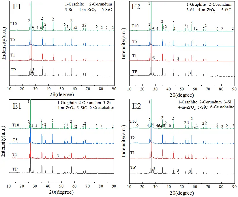
The phase composition of the specimens was analyzed using X-ray diffraction (XRD, X’Pert Pro, Philips, Amsterdam, The Netherlands). The specific phase compositions are shown in Figure 1. During thermal exposure, the Al2O3-C refractories exhibited similar phase compositions, with the most significant reaction being the carbothermal reaction between silicon and graphite to form silicon carbide. Characteristic diffraction peaks of SiC were detected at approximately 35° in all specimens, and the peak intensity increased with prolonged thermal exposure time, indicating the continuous reaction between Si and C to form SiC. Meanwhile, the diffraction peaks of elemental silicon gradually weakened and nearly disappeared, further confirming the occurrence of the carbothermal reduction reaction. The introduction of expanded graphite promoted the formation of SiC to some extent, resulting in a slight increase in the intensity of the SiC diffraction peaks. Additionally, weak cristobalite diffraction peaks were observed in the E1 sample. This is attributed to the fact that expanded graphite, with its large specific surface area and interconnected porous structure, facilitates inward oxygen diffusion, raising the local oxygen partial pressure and thereby accelerating partial oxidation reactions.
The fracture morphologies of Al2O3-C specimens under four thermal exposure conditions (TP, T1, T5, T10) are shown in Figure 2. The microstructures were analyzed using a scanning electron microscope (SEM) equipped with energy dispersive X-rays (EDX) (SEM, Quanta 400, Hillsboro, OR, USA). It can be observed that as service time increases, the fracture surface gradually changes from smooth to rough, with the appearance of numerous fibrous structures, indicating a reaction between Si and C to form SiC whiskers. The F2 sample contains significantly more whiskers than F1, with a more uniform distribution and a higher aspect ratio, reflecting that a higher carbon content promotes the nucleation and growth of whiskers. For the E1 sample, distinct SiC whiskers can already be observed at the T1, suggesting that the layered structure of expanded graphite relieves thermal stress concentration during thermal exposure, improves interfacial reaction conditions, and facilitates early-stage whisker formation. In contrast, the E2 sample shows no obvious whiskers at the T1, which may be attributed to the introduction of expanded graphite, which alters the local pore structure and gas-phase conditions, thereby affecting the nucleation and growth of SiC whiskers.
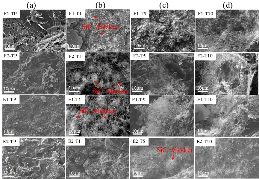
Figure 2. Fracture morphology of Al2O3-C specimens at different thermal exposure: (a) TP; (b) T1; (c) T5; (d) T10.
The bulk density and apparent porosity of the specimens were determined using the Archimedes method with kerosene as the medium. The uniaxial compressive strength (UCS) was tested using a computer-controlled electronic universal testing machine (ETM-EX) at a loading rate of 2 MPa/s, with three parallel specimens tested per group. The longitudinal wave velocity was measured using an ultrasonic flaw detector to evaluate the internal structural integrity of the materials. The basic physical properties of the specimens are presented in Figure 3. Considering the dynamic impact environment of Al2O3-C refractories in actual service, three impact velocities were set: 2.7 m/s, 3.5 m/s, and 4.3 m/s. The specimens were uniformly labeled according to carbon content, presence or absence of expanded graphite, impact velocity, and thermal exposure condition.
The results indicate that material properties exhibit distinct stage-wise evolution during thermal exposure, with markedly different responses depending on the carbon content system. At the initial stage (T1), carbothermal reactions occur in all materials, with in-situ formed SiC filling pores and reinforcing interfaces, leading to decreased apparent porosity and increased bulk density and compressive strength. Among them, F1 and E1 exhibit higher ultrasonic velocity and strength due to their initially dense structure, while F2 and E2, though more porous, show significant property improvement owing to SiC formation. As thermal exposure extends to T5-T10, thermal stress accumulation initiates and propagates microcracks. In high-carbon systems, thermal expansion mismatch between the carbon phase and ceramic phase promotes microcracking at interfaces, compromising the continuity of the load-bearing skeleton and resulting in a decrease in strength. In contrast, the ceramic phase in low-carbon systems further enhances uniaxial compressive strength, demonstrating superior structural stability.
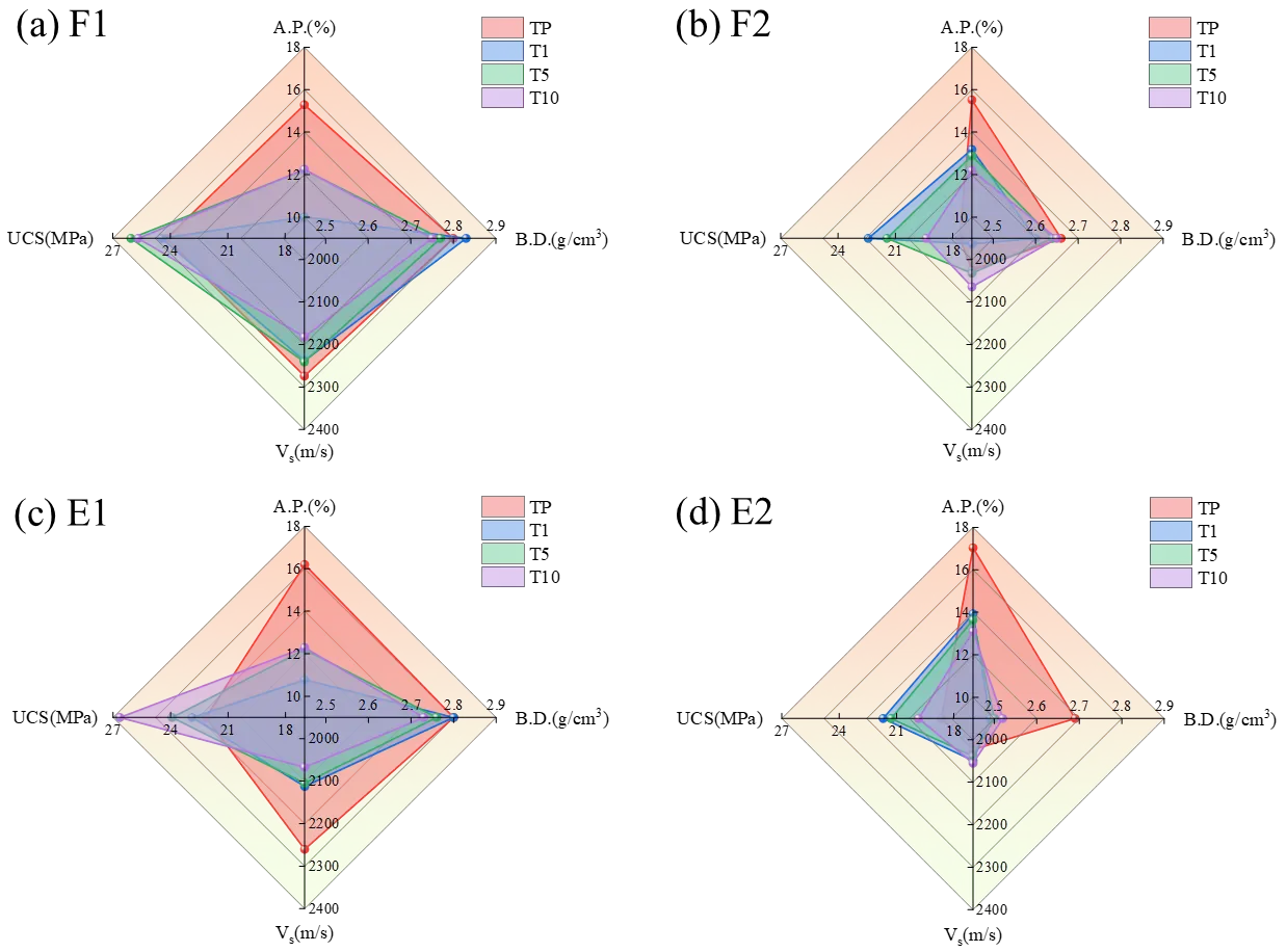
Figure 3. Radar charts comparing four properties of the formulations (a) F1; (b) F2; (c) E1; (d) E2. at different thermal exposure condition.
2.2. Split-Hopkinson Pressure Bar Experiments (SHPB)
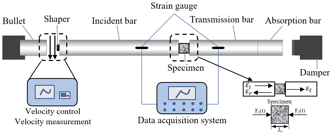
The dynamic compressive strength of Al2O3-C refractories was obtained at room temperature through Split Hopkinson Pressure Bar (SHPB) tests. A schematic diagram of the SHPB apparatus is shown in Figure 4, with its main components including the striker bar (impact bar), incident bar, transmission bar, absorption bar, damper, and data acquisition system.
The SHPB test procedure is as follows: First, a double-sided grinder is used to control the flatness deviation at both ends of the cylindrical specimen within 0.02 mm. The specimen is then placed between the incident bar and the transmission bar, ensuring alignment with the axes of the two bars. A layer of Vaseline is applied to the end faces of the specimen as a lubricant to reduce end-face friction. Subsequently, high-pressure nitrogen is regulated to propel the striker bar at a specific velocity, thereby impacting the incident bar and generating an incident wave. Due to the difference in wave impedance between the specimen and the bars, the stress wave is reflected and transmitted at the specimen interfaces, forming reflected and transmitted waves. Strain gauges mounted on the incident and transmission bars simultaneously capture the waveform signals of the incident, reflected, and transmitted waves.
In this study, steel bars were used. The lengths of the striker bar, incident bar, and transmission bar were 600 mm, 5000 mm, and 3000 mm, respectively, all with a diameter of 100 mm. The elastic modulus of the bars was 190.3 GPa, and the stress wave propagation velocity within the bars was 5000 m/s. The SHPB is a classic experimental apparatus for investigating the dynamic mechanical properties of materials at high strain rates. Its core principle is based on the theory of one-dimensional stress-wave propagation in elastic bars: by measuring the strain pulses in the incident and transmitted bars and assuming stress equilibrium across the specimen, the dynamic stress-strain relationship of the material can be obtained.
3. Results and Discussion
3.1. Fracture Debris Analysis
Using Image-Pro software, the fragment edges are identified (solid red lines), and the length from the center to the edge of each fragment is measured (solid blue lines), as seen in Figure 5. The average length is then calculated as the fragment size. By determining the average fragment size (green numbers), the cumulative size distribution of fragments larger than 5 mm is obtained. For specimen F2-T10, as impact velocity increased from 3.5 m/s to 4.3 m/s, fragment number rose sharply, overall fragment size decreased, and cracks propagated rapidly. At 3.5 m/s, the specimen remained largely intact with localized fractures and a few large blocks. At 4.3 m/s, thorough fragmentation occurred, cracks propagated multidirectional between aggregates and matrix, and abundant fine fragments (<15 mm) appeared, signifying a transition from blocky to pulverization fracture. The particle size distribution showed ~80% volume fraction of fragments <15 mm, a marked decline in large fragments (>45 mm), and a cumulative curve that rises steeply, then levels off, indicating a small-size concentration. Cyclic prolonged thermal exposure T10 formed a dense interfacial layer in F2, which helped maintain structural integrity under low-to-medium impact. However, under high impact loading, this dense structure reduced strain relief space, hindered crack energy dissipation, and led to brittle fracture at critical stress.
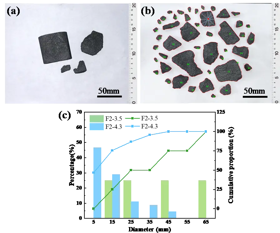
Figure 5. Macroscopic damage: (a) F2-T10-3.5 and (b) F2-T10-4.3, along with (c) fragments size distribution (column) and cumulation (curve).
Figure 6a–d shows marked differences in failure degree among specimens. F1-T10-3.5 and F2-T10-3.5 retained large blocky fragments with few fines, indicating high crack propagation resistance and structural stability. In contrast, E1-T10-3.5 and E2-T10-3.5 exhibited more severe fragmentation dominated by irregular small-to-medium blocks. Cumulative particle size distribution curves (Figure 6e) reveal that F1, F2, and E1 share similar fragment size distributions, with curves rising gradually as particle size increases, suggesting failure dominated by multi-crack propagation and coalescence, yielding a dispersed size distribution. The curve for E2 shows a sharp increase near 55 mm, corresponding to macroscopic fracture into three similarly sized large fragments. This indicates that under higher carbon content, the introduction of expanded graphite enhances material integrity under dynamic impact, with blocky fracture as the dominant failure mode.
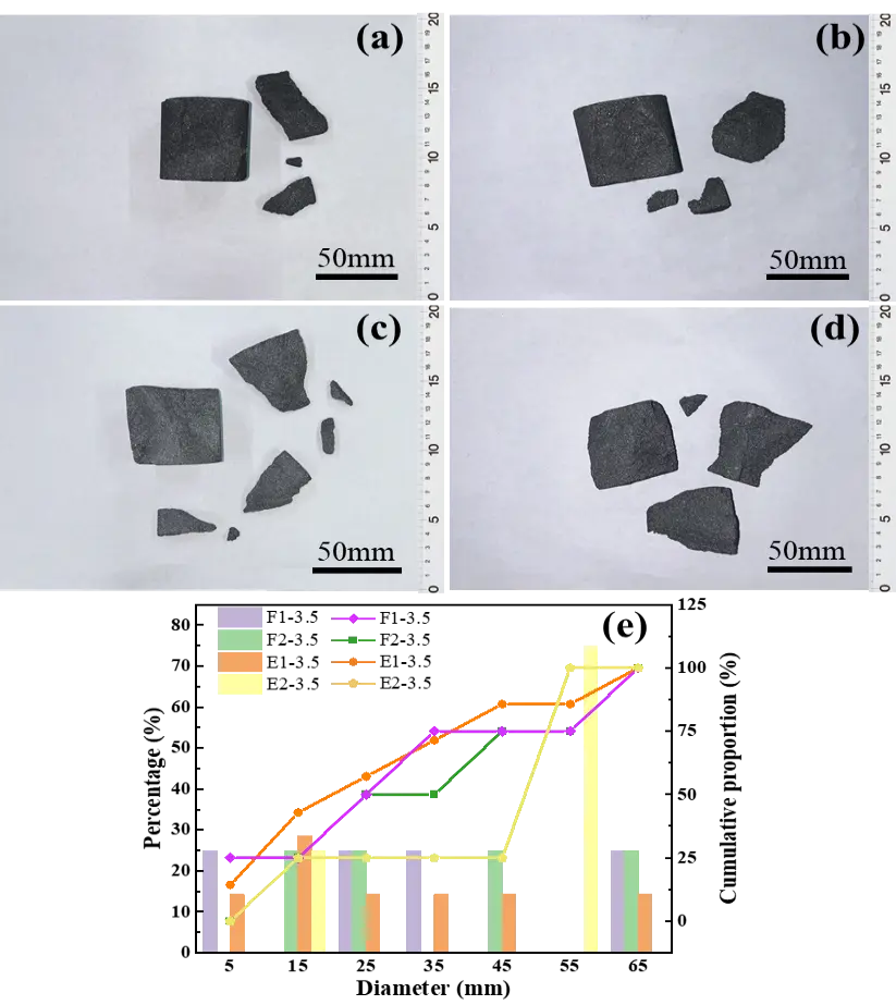
Figure 6. Macroscopic damage: (a) F1-T10-3.5; (b) F2-T10-3.5; (c) E1-T10-3.5, (d) E2-T10-3.5, along with (e) fragments size distribution (column) and cumulation (curve).
Figure 7 shows the fracture fragment morphology and particle size distribution of specimen F2 at 3.5 m/s under different thermal exposure. As temperature and holding time increase, damage decreases, and morphology shifts from numerous fragments to a few large blocks, indicating that high-temperature treatment improves impact resistance. Under TP, the specimen suffers severe fragmentation into irregular small-to-medium fragments, reflecting weak bonding. T1 strengthens the matrix and increases density, notably reducing fragment count. Extending the holding time to T5 yields larger fragments and far fewer fines. Under T10, the specimen breaks into only 2–3 large blocks with negligible fines, demonstrating strong integrity and impact resistance. Particle size distribution curves (Figure 7e) show that under TP, small fragments (<15 mm) account for ~70%, and the cumulative curve rises sharply, confirming fine-fragment-dominated failure and poor matrix bonding. Under T1, T5, and T10, small-fragment proportion declines while medium-to-large fragments (35–65 mm) increase, consistent with morphology changes.
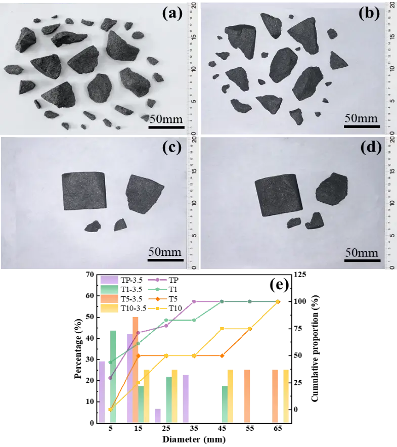
Figure 7. Macroscopic damage: (a) F2-TP-3.5; (b) F2-T1-3.5; (c) F2-T5-3.5 and (d) F2-T10-3.5 along with (e) fragments size distribution (column) and cumulation (curve).
3.2. Reliability Analysis for Al2O3-C Specimens Tested with SHPB
Based on the one-dimensional stress wave theory, the stress (σ), strain (ε), and strain rate ($$\stackrel{\mathrm{˙}}{\text{ε}}$$) of the specimen can be calculated using the three-wave method [24]. To ensure the reliability of SHPB test results, it is necessary to verify the dynamic stress equilibrium within the specimen during loading [25]. This verification is based on the uniformity assumption underlying SHPB testing, i.e., once the specimen achieves dynamic stress equilibrium, its stress state can be regarded as equivalent to that under quasi-static loading conditions.
|
```latex\sigma \left(t\right)=\frac{{A}_{1}{E}_{1}}{2{A}_{2}}\left[{\epsilon }_{i}\left(t\right)+{\epsilon }_{r}\left(t\right)+{\epsilon }_{t}\left(t\right)\right]``` |
(1) |
|
```latex\epsilon \left(t\right)=\frac{{C}_{0}}{{L}_{s}}{\int }_{0}^{t}\left[{\epsilon }_{i}\left(t\right)-{\epsilon }_{r}\left(t\right)-{\epsilon }_{t}\left(t\right)\right]dt``` |
(2) |
|
```latex\dot{\epsilon }\left(t\right)=\frac{{C}_{0}}{{L}_{s}}\left[{\epsilon }_{i}\left(t\right)-{\epsilon }_{r}\left(t\right)-{\epsilon }_{t}\left(t\right)\right]``` |
(3) |
|
```latex{\epsilon }_{r}+{\epsilon }_{i}={\epsilon }_{t}``` |
(4) |
where A1 is the cross-sectional area of the bar, A2 is the cross-sectional area of the specimen, E1 is the elastic modulus of the bar, Ls is the thickness of the specimen; C0 is the longitudinal wave velocity of the bar; and εi, εr, and εt are the incident wave, reflected wave, and transmitted wave, respectively.
When stress balance is achieved, the sum of the incident and reflected waves should equal the transmitted wave. Due to possible time lag during wave propagation, the waveforms typically need to be aligned to eliminate phase differences, allowing an accurate comparison of their coincidence. After alignment, if the waveform curve of $${\epsilon }_{r}+{\epsilon }_{i}$$ closely matches that of $${\epsilon }_{t}$$, the stress balance condition is satisfied for this test case, and the experimental data are valid. Otherwise, issues such as poor contact between the specimen and the pressure bars, uneven wave propagation, or other experimental anomalies may exist, requiring parameter readjustment.
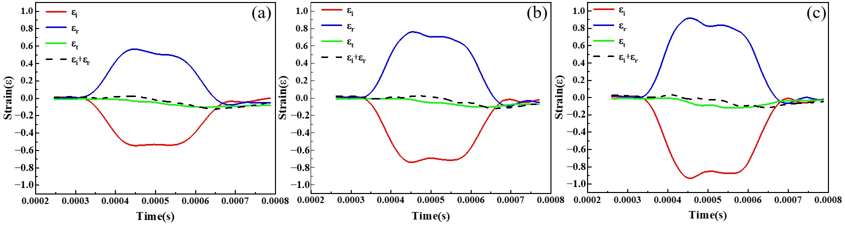
To systematically verify the data reliability under different dynamic response conditions, this study selected typical failure modes of specimen F2 at impact velocities of 2.7 m/s, 3.5 m/s, and 4.3 m/s, and performed stress balance analysis on the corresponding waveforms. The results are shown in Figure 8. With increasing impact velocity, the stress on the material increases accordingly. Nevertheless, the waveforms at different impact velocities exhibit good coincidence, particularly near the peak strain, where the agreement is even higher. This indicates that in the present tests, the specimens well satisfied the stress balance condition, thereby ensuring the reliability of the dynamic damage data obtained for the Al2O3-C refractories via SHPB testing.
Al2O3-C refractories exhibit strain rate sensitivity, with their mechanical properties varying significantly with loading rate. In SHPB experiments, dynamic loading of specimens at different strain rates can be achieved by adjusting the driving gas pressure to control the impact velocity of the striker bar. It should be noted that the strain rate characterizes the deformation rate of a material per unit time, and its stable control is crucial for obtaining reliable dynamic mechanical properties. However, due to the extremely short duration of the SHPB impact process, real-time adjustment of the impact velocity during the test is not feasible. Therefore, it is essential to calculate a representative strain rate from the test signals. Considering that the stress state is often unstable at the initial stage of impact, this study takes the strain rate within the range of 80% of the peak stress as the average strain rate of the specimen. This approach can mitigate, to some extent, the influence of fluctuations during the initial loading stage.
Figure 9 shows the stress and strain rate versus time curves under low-velocity and high-velocity impact. In the figure, fd denotes the peak stress point of the Al2O3-C specimen, and t0 indicates the duration interval at 80% of the peak stress. As shown in Figure 9a, under low-velocity impact, the strain rate within the t0 interval increases before the peak and decreases rapidly after the peak; under high-velocity impact, the strain rate within the t0 interval remains relatively stable. These results indicate that the average strain rate selected within the stress range of 0.8fd can effectively characterize the constant strain rate under different impact velocities, providing a reasonable basis for dynamic mechanical analysis.
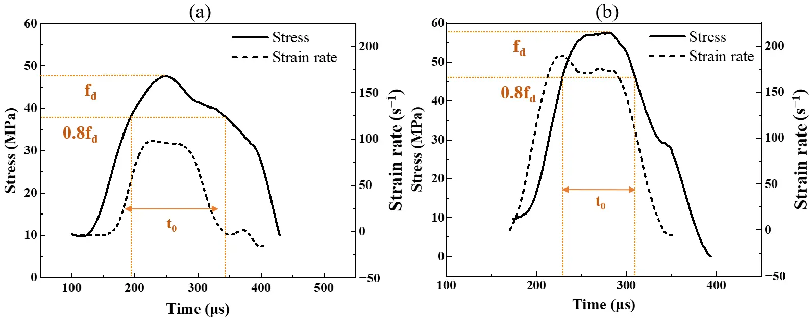
Figure 9. Schematic diagram of average strain rate: (a) at low speed; (b) at high impact velocities.
Figure 10 summarizes the average strain rates of specimens under different impact velocities. The data indicate that the average strain rate increases significantly with impact velocity, exhibiting a typical positive correlation. Under the same thermal exposure conditions, the strain rates at 3.5 m/s and 4.3 m/s are generally higher. Under medium-to-high impact velocities, the strain rates of all specimens decrease after T1 compared with those under the TP, indicating that thermal exposure eliminates some pores and defects, making the material structure denser. With extended thermal exposure time (T1-T10), under medium-to-high impact velocities, the average strain rates of specimens F1 and E1 increase slightly, while those of specimens F2 and E2 show a decreasing trend. Under the T10-4.3 m/s condition, the average strain rates follow the order F2 < E1 < E2 < F1. An appropriate amount of expanded graphite can optimize the interfacial structure, disperse stress, enhance the impact resistance and stability of the material, and reduce its brittleness.
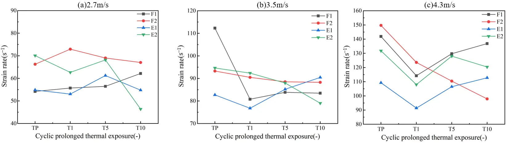
Figure 10. Average strain rate versus thermal exposure time for different formulations at three different speeds: (a) 2.7 m/s; (b) 3.5 m/s; (c) 4.3 m/s.
3.3. Dynamic Mechanical Properties Evaluation
3.3.1. Dynamic Stress-Strain Curve
Figure 11 shows the stress-strain curves of different Al2O3-C specimens under TP, T1, T5, and T10. Overall, as the impact velocity increases, the peak stress of each specimen gradually rises, indicating that the loading rate has a significant effect on the dynamic strength of the material. Under the TP, the specimens generally exhibit a sharp peak stress characteristic, with a rapid post-peak stress drop, suggesting that numerous pores and defects remain within the material, leading to rapid crack propagation and unstable failure after the peak stress. After T1, the peak stress increases slightly; the thermal exposure time improves the interfacial bonding and densification of the material, reduces porosity, and densifies the microstructure, thereby enhancing the load-bearing capacity. With further thermal exposure to the T5 and T10, the overall shape of the curves becomes gentler, the peak stress changes little, but the post-peak fluctuations diminish, indicating that after high-temperature thermal exposure, the strengthening mechanism of the material shifts from strength enhancement to structural homogenization and stress concentration relief, thus improving the stability of the material under dynamic loading. It is worth noting that after T1 thermal exposure, specimen F1 exhibits the highest peak stress, but the post-peak stress drops rapidly, showing typical brittle fracture characteristics. The curves of specimens E1 and F2 tend to be stable, with little change in peak stress. Among them, specimen E1 maintains a relatively high stress level and a gentle post-peak decline under the T10, indicating good toughness and energy dissipation capacity.

Figure 11. Stress-strain curves of Al2O3-C specimens after cyclic prolonged thermal exposure: (a) TP; (b) T1; (c) T5; (d) T10.
To more intuitively present the correlation between dynamic mechanical parameters and strain rate, fitting analyses were performed on the dynamic compressive strength, ultimate strain, and strain energy of Al2O3-C specimens subjected to different thermal exposures against strain rate. As shown in Figure 12, the Al2O3-C specimens exhibit a clear strain rate effect under all thermal exposure conditions, with the dynamic compressive strength, ultimate strain, and strain energy all increasing to varying degrees as the strain rate increases. Among them, specimen F1 consistently shows the highest dynamic compressive strength, indicating its superior load-bearing capacity; specimen F2 exhibits slightly lower strength but better ductility, with generally higher ultimate strain than F1, suggesting that a higher carbon content helps enhance plastic deformation capability.
After the addition of expanded graphite, the compressive strength of specimen E1 does not increase significantly and is even lower than that of F2 at some strain rates. However, its ultimate strain is generally higher than that of F1, indicating that the introduction of expanded graphite does not significantly enhance the material’s load-bearing capacity but effectively improves its toughness. This may be attributed to the formation of flexible interfaces and slip layers in the matrix by expanded graphite, which can disperse stress and absorb impact energy while simultaneously weakening the overall strength. In addition, specimen E2 exhibits relatively stable performance, with its strength close to that of F2 and slightly higher strain energy, suggesting that expanded graphite mainly plays a role in pore refinement and stress buffering in this case.
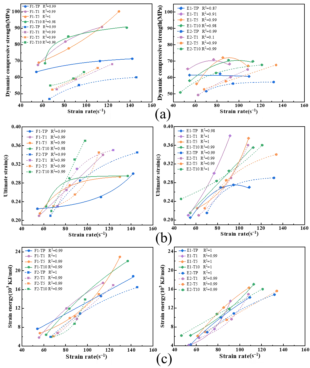
Figure 12. Dynamic compressive strength (a), ultimate strain (b), and strain energy (c) of Al2O3-C specimens as functions of strain rate at various thermal exposure.
3.3.2. Dynamic Increase Factor
To quantify the effect of strain rate on the dynamic compressive strength of Al2O3-C refractories, the dynamic increase factor (DIF) is introduced in this study. The DIF is defined as the ratio of the dynamic compressive strength FD to the static compressive strength FS; a larger DIF value indicates higher strain rate sensitivity of the material. The calculation formula is as follows:
|
```latexDIF=\frac{{F}_{D}}{{F}_{s}}``` |
(5) |
Figure 13 presents the dynamic increase factor (DIF) of Al2O3-C specimens subjected to different thermal exposure conditions. It can be observed that, in the TP, due to the high porosity and weak interfacial bonding, all specimens exhibit relatively low DIF values. After T1 thermal exposure, the DIF of some specimens increases, indicating initial densification of the structure; however, the DIF of F2 and E2 at T1 is slightly lower than that in the TP, suggesting that this condition is insufficient to strengthen their carbon network interfaces. Further to the T5, the DIF of specimen F1 reaches 3.85 at a high strain rate (4.3 m/s), indicating the most significant enhancement and indicating that this temperature effectively promotes grain sintering and interfacial bonding. At the T10, the DIF of F2 and E2 continues to increase, whereas that of F1 and E1 shows a slight decrease.
From the perspective of material systems, F1 exhibits the highest strain-rate sensitivity and the greatest increase in DIF. For the E1 specimen containing expanded graphite, the layered structure provides stress buffering, resulting in overall lower DIF values but improved toughness. In contrast, the DIF of F2 and E2 slightly decreases at T1 and then increases subsequently, indicating that the carbon network has developed effective stress transfer and energy absorption capabilities. In high carbon-content systems, expanded graphite primarily plays an auxiliary role at local interfaces.
Thermal exposure generally enhances the dynamic strengthening performance of the materials; however, the compositional system significantly influences this response. The introduction of expanded graphite helps to balance strain-rate sensitivity and toughness.
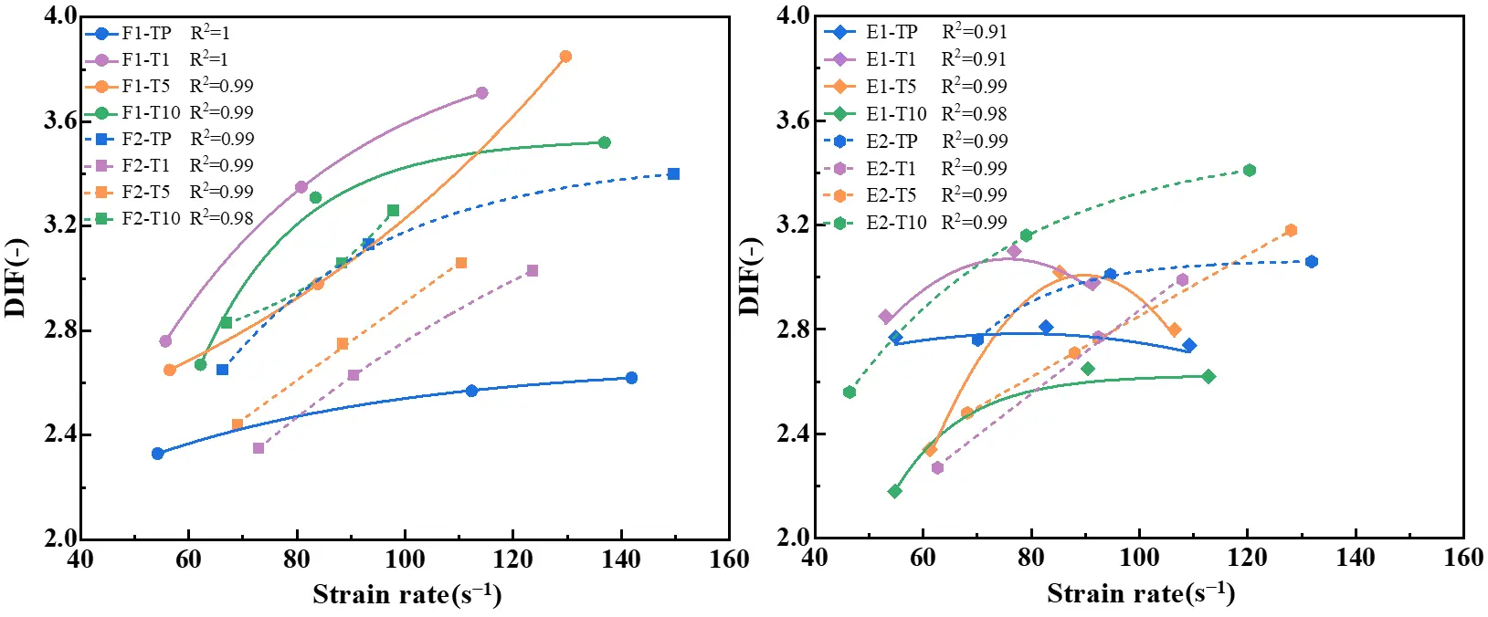
Figure 13. Strain rate-dynamic increase factor curves for Al2O3-C specimens at different thermal exposure.
3.4. Discussion
Previous comparison of dynamic mechanical properties among the four formulations indicates that F2 and E1 exhibit similar mechanical responses, supporting the preliminary feasibility of replacing F2 with E1. Nevertheless, practical engineering applications demand both dynamic mechanical performance and stable service under harsh conditions, in which thermal shock resistance, oxidation resistance, and cyclic loading fatigue life are critical for long-term reliability.
Figure 14a shows the flexural strength and retention rate of specimens after three thermal shock tests at 950 °C. The strength of all specimens decreased to some extent: F2 exhibited a retention rate of 87%, while E1 achieved 93%, demonstrating excellent thermal shock resistance. This indicates that the combined addition of an appropriate carbon content and expanded graphite helps relieve thermal stress concentration and inhibit crack propagation, thereby improving structural integrity and performance stability after thermal shock. Further analysis of oxidation behavior was conducted using post-oxidation cross-sectional images (Figure 14b). Cross-sections are divided into oxidation layer (black-red line), decarburized layer (red-white line), and original layer (inside white line). At 950 °C, oxidation was limited to the surface with edge spalling but an intact core, indicating that at lower temperatures, oxygen diffusion is limited and oxidation is primarily controlled by gas-phase diffusion. At 1500 °C, the oxidation zone expanded significantly, the section turned grayish-white, and the oxidation index rose to ~65%, indicating deeper oxygen penetration into the matrix at high temperatures. Despite similar oxidation zones, the E1 specimen exhibited better oxidation resistance.
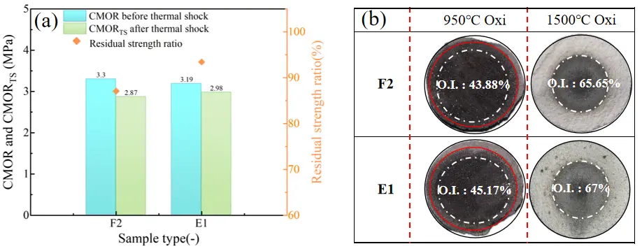
The fatigue performance of specimens under cyclic loading was studied using repeated loading-unloading tests. Taking F2 and E1 as examples, the multiple loading-unloading process revealed the materials’ deformation recovery and damage failure modes during stress accumulation and release. Simultaneously, digital image correlation (DIC) was used for real-time observation of fracture behavior, clearly capturing the entire process of crack initiation, propagation, and final unstable fracture.
Figure 15 presents the force-displacement curves of the specimens under cyclic loading, along with the crack propagation paths and strain evolution characteristics during the fracture process. After thermal exposure at 1500 °C, the strength of the materials generally increased, attributed to the densification of the matrix promoted by high-temperature reactions. Specimen F2 exhibits higher cyclic load-bearing capacity and a more gradual load attenuation. Specimen E1 shows a cyclic behavior similar to that of F2, with a slightly lower peak load but better stability, indicating that the sliding energy absorption of expanded graphite effectively delays crack propagation. Under the untreated condition (950 °C), the strain concentration zone rapidly penetrates the specimen in the first loading cycle, with rapid crack propagation, exhibiting typical brittle fracture. After 1500 °C, the strain distribution becomes more uniform, crack initiation is delayed, and the propagation path is more tortuous, indicating that densification and interfacial strengthening inhibit crack propagation. For E1 under the 1500 °C condition, the strain distribution during loading is more uniform, and crack propagation is delayed, further demonstrating that the interlayer sliding of expanded graphite acts as a stress buffer and crack blunting mechanism.
The worm-like structure of the introduced expanded graphite significantly enhances interfacial bonding and crack propagation paths. In low-carbon systems, this structure effectively offsets the toughness loss from reduced carbon content, enabling a synergistic improvement in both strength and fracture toughness.
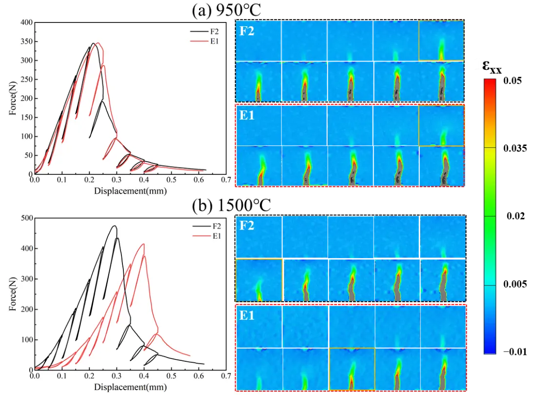
Figure 15. Cyclic loading force-displacement curves and DIC-monitored fracture process of the material at different temperatures. (a) 950 °C; (b) 1500 °C.
4. Conclusions
In this study, SHPB impact tests were conducted on Al2O3-C refractories subjected to different thermal exposure and partially substituted with expanded graphite, at impact velocities of 2.7 m/s, 3.5 m/s, and 4.3 m/s. The effects of microstructure and test conditions on the dynamic mechanical behavior were investigated, and the following conclusions were drawn:
- (1)
-
The dynamic failure mode of Al2O3-C specimens evolves from surface microcracks to block fracture and ultimately to pulverization with increasing impact velocity. Fragment mass ratio analysis shows that the proportion of fragments smaller than 5 mm increases with impact velocity, indicating that the severity of damage is positively correlated with impact velocity. The introduction of expanded graphite delays crack propagation through interlayer sliding and stress buffering, effectively suppressing the fragmentation process under high-speed impact conditions, thereby enhancing the material’s impact damage resistance and fracture stability.
- (2)
-
The material composition plays a critical role in balancing strength, toughness, and strain rate effects. F1 exhibits the highest strength but poor fracture toughness, characterized by brittle fracture. F2 maintains relatively high strength while demonstrating better ductile fracture characteristics. Although E1 does not show a significant increase in strength due to the stress buffering and crack blunting effects of expanded graphite, its toughness and energy dissipation capacity are markedly enhanced. E2 retains good energy absorption capacity even under high strain rate conditions.
- (3)
-
With increasing thermal exposure time, the compressive strength, ultimate strain, and strain energy of the F1, E1, and F2 specimens exhibit staged variations, with the specimens showing optimal comprehensive impact resistance at T5. Due to the interfacial buffering and crack deflection effects of expanded graphite during thermal exposure, E1 exhibits significantly improved damage tolerance, albeit with a slight reduction in compressive strength. Additionally, its dynamic enhancement factor initially increases and then decreases with increasing strain rate, indicating a reduced strain rate sensitivity of the material’s strength.
Statement of the Use of Generative AI and AI-Assisted Technologies in the Writing Process
During the preparation of this manuscript, the authors used AI-based tools for the purpose of language polishing and grammatical correction. No other AI applications, including data analysis, interpretation, or generation of results, were employed.
Acknowledgments
All authors gratefully acknowledge Guangzhao Bai and Wei Zhang for their great support of samples preparation, SHPB tests etc.
Author Contributions
Z.W.: Conceptualization, Methodology, Literature review, Writing—original draft, Writing—review & editing. H.W.: Methodology, Literature review, Writing—review & editing. T.Z.: Writing—review & editing, Literature review. J.Y.: Supervision, Funding acquisition, Review & editing. S.J.: Funding acquisition, Review & editing. Y.L.: Supervision, Review & editing. Y.D.: Conceptualization, Funding acquisition, Supervision, Writing—review & editing
Ethics Statement
Not applicable.
Informed Consent Statement
Not applicable.
Data Availability Statement
Not applicable.
Funding
The financial support from the National Natural Science Foundation of China (No. 52472303), Wuhan Natural Science Foundation Exploration Program (No. 2025040601020146), and Hubei Provincial Special Fund for Central-Guided Local S&T Development (No. 2025CSA017) are appreciated. Supported by the Open Project Program of State Key Laboratory of Advanced Refractories, (Grant No. SKLAR26040YW).
Declaration of Competing Interest
The authors declare that they have no known competing financial interests or personal relationships that could have appeared to influence the work reported in this paper.
References
- Xu L, Bao H, Bao Z, Gao S, Chen M, Wang N. Microstructure, properties, and application of low carbon Al2O3‐C refractories used as submerged entry nozzles. Int. J. Appl. Ceram. Technol. 2020, 17, 657–667. DOI:10.1111/ijac.13388 [Google Scholar]
- Zhang J, Liu Q, Yang S, Chen Z, Li J, Jiang Z. Advances in Ladle Shroud as a Functional Device in Tundish Metallurgy: A Review. ISIJ Int. 2019, 59, 1167–1177. DOI:10.2355/isijinternational.ISIJINT-2019-044 [Google Scholar]
- Xing L, Liu J, Bao Y, Wang M. Corrosion mechanism of Al2O3–C stopper rod by calcium treated molten steel. J. Mater. Res. Technol. 2025, 34, 924–931. DOI:10.1016/j.jmrt.2024.12.132 [Google Scholar]
- Song JW, Yan W, Chen Z, Liu Y, Hong SS. Effect of nano-carbon black content on wetting phenomenon of molten steel and alumina–carbon ceramic filter substrates. J. Iron Steel Res. Int. 2024, 31, 1900–1913. DOI:10.1007/s42243-024-01193-7 [Google Scholar]
- Lv J, Zhang H, Gu H, Liang F. A Review on the Application of Nanomaterials to Boost the Service Performances of Carbon-Containing Refractories. High-Temp. Mater. 2024, 1, 10005. DOI:10.70322/htm.2024.10005 [Google Scholar]
- Chen Z, Yan W, Schafföner S, Li Y, Li N. Microstructure and mechanical properties of lightweight Al2O3-C refractories using different carbon sources. J. Alloys Compd. 2021, 862, 158036. DOI:10.1016/j.jallcom.2020.158036 [Google Scholar]
- Zhang T, Chen T, Liu Z, Yu C, Deng C, Ding J, et al. Enhancement and evaluation of strength stability of low-carbon Al2O3–C refractories based on ceramic phase distribution modulation. Ceram. Int. 2025, 51, 4946–4956. DOI:10.1016/j.ceramint.2024.11.466 [Google Scholar]
- Sarath Chandra K, Sarkar D. Structural properties of Al2O3–MgO–C refractory composites improved with YAG nanoparticle hybridized expandable graphite. Mater. Sci. Eng. A 2021, 803, 140502. DOI:10.1016/j.msea.2020.140502 [Google Scholar]
- Liao N, Li Y, Jin S, Sang S, Harmuth H. Enhanced mechanical performance of Al2O3-C refractories with nano carbon black and in-situ formed multi-walled carbon nanotubes (MWCNTs). J. Eur. Ceram. Soc. 2016, 36, 867–874. DOI:10.1016/j.jeurceramsoc.2015.10.003 [Google Scholar]
- Wang Q, Li Y, Luo M, Sang S, Zhu T, Zhao L. Strengthening mechanism of graphene oxide nanosheets for Al2O3–C refractories. Ceram. Int. 2014, 40, 163–172. DOI:10.1016/j.ceramint.2013.05.117 [Google Scholar]
- Behera SK, Mishra B. Strengthening of Al2O3-C slide gate plate refractories with expanded graphite. Ceram. Int. 2015, 41, 4254–4259. DOI:10.1016/j.ceramint.2014.11.092 [Google Scholar]
- Wang Q, Li Y, Sang S, Jin S. Effect of the reactivity and porous structure of expanded graphite (EG) on microstructure and properties of Al2O3–C refractories. J. Alloys Compd. 2015, 645, 388–397. DOI:10.1016/j.jallcom.2015.05.124 [Google Scholar]
- Liang X, Wang L, Liu Z, Li Z, Luo X, Wu F, et al. Thermal, flow and inclusions analysis of clogging mechanism in continuous casting process. Case Stud. Therm. Eng. 2025, 65, 105602. DOI:10.1016/j.csite.2024.105602 [Google Scholar]
- Tian C, Zhi J, Gan F, Fan Z, Gao H, Yuan L, et al. Improving the erosion resistance of the submerged entry nozzle by applying an external electric field. Ceram. Int. 2023, 49, 4240–4251. DOI:10.1016/j.ceramint.2022.09.308 [Google Scholar]
- Fu Z, Dai Y, Xu X, Zhu T, Zhang W, Zhang J, et al. Dynamic failure of magnesia-carbon refractories under uniaxial compressive load. Ceram. Int. 2024, 50, 33703–33716. DOI:10.1016/j.ceramint.2024.06.188 [Google Scholar]
- Fu Z, Dai Y, Zhu T, Wang H, Xu X, Andreev K, et al. Dynamic splitting tensile mechanical behavior of magnesia-carbon refractories under impact loading. J. Eur. Ceram. Soc. 2025, 45, 116914. DOI:10.1016/j.jeurceramsoc.2024.116914 [Google Scholar]
- Abdul-Rahman R, Saletti D, Forquin P. Experimental study of the static and dynamic behavior of pre-stressed concrete subjected to shear loading. Eng. Struct. 2021, 234, 111865. DOI:10.1016/j.engstruct.2021.111865 [Google Scholar]
- Grigoriev AS, Zabolotskiy AV, Shilko EV, Dmitriev AI, Andreev K. Analysis of the Quasi-Static and Dynamic Fracture of the Silica Refractory Using the Mesoscale Discrete Element Modelling. Materials 2021, 14, 7376. DOI:10.3390/ma14237376 [Google Scholar]
- Sadowski T, Pietras D. Estimation of mechanical response of 2-phase oxide ceramic composites under high strain rate. Mater. Today Proc. 2021, 45, 4286–4291. DOI:10.1016/j.matpr.2020.12.774 [Google Scholar]
- Xu X, Jing H, Yin Q, Wu J, Guzev MA, Jin J. Dynamic Compressive Mechanical Properties of Rock-like Material with Bedding Planes Subject to Different Impact Loads. KSCE J. Civ. Eng. 2024, 28, 2409–2419. DOI:10.1007/s12205-024-1145-x [Google Scholar]
- Hao Y, Hao H, Jiang GP, Zhou Y. Experimental confirmation of some factors influencing dynamic concrete compressive strengths in high-speed impact tests. Cem. Concr. Res. 2013, 52, 63–70. DOI:10.1016/j.cemconres.2013.05.008 [Google Scholar]
- Song Y, Ma H, Yang J, Zheng J, Yang J, Bao W. Dynamic Mechanical Behaviors and Failure Mechanism of Lignite under SHPB Compression Test. Sustainability 2022, 14, 10528. DOI:10.3390/su141710528 [Google Scholar]
- Zhe R, Zhou W. Study of dynamic mechanical properties of UHPC-AAC composites based on SHPB test. J. Build. Eng. 2023, 78, 107668. DOI:10.1016/j.jobe.2023.107668 [Google Scholar]
- Yang Y, Li Q, Qiao L. Review of SHPB Dynamic Load Impact Test Characteristics and Energy Analysis Methods. Processes 2023, 11, 3029. DOI:10.3390/pr11103029 [Google Scholar]
- Lv TH, Chen XW, Chen G. Analysis on the waveform features of the split Hopkinson pressure bar tests of plain concrete specimen. Int. J. Impact Eng. 2017, 103, 107–123. DOI:10.1016/j.ijimpeng.2017.01.004 [Google Scholar]