
High Temperature Fatigue Crack Growth Kinetics of a High Performance Ferritic (HiperFer) Steel
High Temperature Fatigue Crack Growth Kinetics of a High Performance Ferritic (HiperFer) Steel
Torsten Fischer
1
Bernd Kuhn
2,*

Received: 11 May 2026 Revised: 26 May 2026 Accepted: 09 June 2026 Published: 30 June 2026

© 2026 The authors. This is an open access article under the Creative Commons Attribution 4.0 International License (https://creativecommons.org/licenses/by/4.0/).
1. Introduction
The development of advanced thermal power conversion systems has traditionally been driven by the need to improve resource efficiency, hence maximizing the economic performance of power plants. In recent years, however, structural changes in the electricity generation sector have significantly altered the operational conditions of conventional thermal power plants. In particular, the increasing penetration of intermitting renewable energy sources, such as wind and solar power, introduces pronounced fluctuations in electricity supply. Furthermore, concentrating solar power (CSP) [1,2] systems and molten salt-based thermal energy storage (TES) as representative technologies for thermal energy generation and storage, in conjunction with downstream Clausius-Rankine steam cycles for electricity generation in solar thermal and heat storage power plants [3], impose highly dynamic fluctuations in operating conditions on the structural materials employed. To maintain grid stability, conventional thermal power plants are therefore required to operate more flexibly and frequently adjust their load [4]. Consequently, components in the hot sections of these plants are increasingly subjected to combined creep and cyclic loading rather than steady-state creep conditions. The change in loading schedule promotes accelerated crack propagation and thus results in a reduced lifetime compared to predominant creep loading [5,6]. In parallel, efforts are being directed towards improving the efficiency of these power plants by increasing the operating temperatures beyond 650 °C, which also contributes to a reduction in CO2 emissions [7,8]. For these reasons, steels of increased fatigue strength, as well as high resistance to corrosion and creep strength at elevated temperatures, are required. Advanced ferritic-martensitic (AFM) steels with 9–12% chromium, commonly used in power generation, were originally designed for high creep strength at temperatures between 580 and 620 °C [9]. Under cyclic loading, they exhibit pronounced cyclic softening and microstructural instability, which can significantly reduce fatigue and creep-fatigue lifetime [10,11,12]. Owing to their comparably low chromium content, these steels provide limited corrosion resistance only when exposed to temperatures exceeding 620 °C [9,13]. Moreover, their limited downtime corrosion resistance represents a primary cause of the significant increase in conservation expenses for flexibly operated German power plants [14]. Consequently, there is a demand for novel cost-effective high-performance structural materials. High-chromium ferritic steels have emerged as promising candidates, prompting ongoing research into their development [15,16,17]. In AFM steels like P91, strengthening is mainly provided by M23C6 (M: Cr, Mo) and MX (M: V, Nb; X: N) precipitates, in addition to solid solution and sub-grain strengthening [18]. In contrast, the high chromium fully ferritic steel Crofer®22 H developed at Forschungszentrum Jülich GmbH (Jülich, Germany) derives its strength primarily from solid solution hardening and the formation of intermetallic Laves phase precipitates of the (Fe,Cr,Si)2(Nb,W) type [19]. This strengthening concept is applied because the solubility of carbon and nitrogen in the ferritic matrix is limited, preventing the effective use of carbide and nitride precipitates. Due to its high chromium content, Crofer®22 H provides adequate resistance to steam oxidation at temperatures up to 650 °C [19].
Under dominant cyclic loading conditions, the total lifetime of a material comprises the technical lifetime until crack formation, encompassing short crack initiation and growth (described by low cycle fatigue (LCF) or thermo-mechanical fatigue (TMF)), followed by the residual lifetime. In the application relevant temperature range up to 650 °C, Crofer®22 H exhibited a thermomechanical fatigue lifetime up to technical cracking, which was approximately 40% higher than that of grade 92 steel, while at 650 °C its residual lifetime, which is governed primarily by crack propagation, was up to five times longer [20]. Superior fatigue resistance of Crofer®22 H steel can be attributed to strengthening arising from the continuous thermomechanically induced precipitation of Laves phase particles, promoted by elevated dislocation density [21]. Although Crofer®22 H exhibits excellent high-temperature properties, the underlying alloying concept still offers considerable potential for further development. Consequently, Crofer®22 H has been further developed into High performance Ferritic (HiperFer) steels [22]. In the HiperFer 17Cr2 trial alloy investigated in this study, the chromium content was reduced to a lower the extent of (Fe, Cr) σ-phase formation and material cost without compromising excellent steam oxidation resistance. Furthermore, the W- and Nb-contents were increased in order to boost Laves phase volume fraction [19,23] and solid solution strengthening. Nb and Si accelerate Laves phase formation [24], while W retards it, but increases solid solution strengthening [25]. Thus, a carefully controlled balance between these three elements is needed to achieve the desired precipitation kinetics. Further improvements include the reduction of process-related impurities to enhance microstructural homogeneity, as well as the optimization of heat treatment [21,26]. Increased dislocation density (e.g., due to mechanical or thermo-mechanical loading) promotes the Laves phase in HiperFer steel, with dislocations serving as nucleation sites [19,21]. The 17Cr2 trial alloy demonstrated almost double the lifetime up to technical cracking under TMF conditions. In isothermal low-cycle loading (LCF), higher stress amplitudes and longer lifetimes were achieved compared to Grade 92 [21]. As material costs and, consequently, plant efficiency become increasingly critical in the context of the energy transition, extending the residual lifetime and enabling higher operating temperatures are of growing importance. This study, therefore, investigated the crack propagation behavior in HiperFer 17Cr2 at temperatures between 650 °C and 675 °C, along with the underlying microstructural mechanisms. For comparison, the crack propagation behavior of HiperFer 17Cr2 was benchmarked against the AFM-steel P91 at the main testing temperature of 650 °C. In the case of HiperFer 17Cr2, the upper temperature of 675 °C was chosen to assess the effects of temporarily limited temperature spikes and to enable an estimate of potentially even higher temperature capacity.
2. Materials and Methods
2.1. HiperFer 17Cr2 and P91
The HiperFer 17Cr2 trial alloy applied in this study had the chemical composition given in Table 1.
Table 1. Chemical composition (wt.%) of HiperFer 17Cr2 and P91.
|
Material |
Element in wt.% C |
N |
Cr |
Mn |
Si |
Nb |
W |
V |
Ni |
Mo |
|---|---|---|---|---|---|---|---|---|---|---|
|
HiperFer 17Cr2 |
<0.01 |
<0.01 |
17.1 |
0.18 |
0.25 |
0.63 |
2.41 |
- |
- |
- |
|
P91 |
0.101 |
0.041 |
8.8 |
0.44 |
0.36 |
0.07 |
- |
0.21 |
0.26 |
0.91 |
Specimens were extracted from hot-rolled HiperFer 17Cr2 sheet material by water jet cutting and subsequently electrically discharge machined (EDM) into the compact tension geometry described in Section 2.2. The machined specimens were recrystallized at 1050 °C for 15 min under an inert atmosphere, followed by air cooling. Subsequently, a two-step precipitation heat treatment was applied, consisting of annealing at 545 °C for 5 h followed by water quenching, and a second annealing step at 650 °C for 1 h, also followed by water quenching. The typical microstructure of 17Cr2 is described in [21,22,23] and consists of intra- and intergranular precipitation of finely dispersed Laves phase particles, which effectively strengthen the material. High-angle grain boundaries (HAGbs) are covered by Laves phase particles and are characterized by adjacent particle-free zones (PFZs) alongside. The formation of these PFZs is influenced by both alloy composition and heat treatment.
The key factor governing fatigue properties is the thermomechanically induced precipitation of Laves phase precipitates. Under thermal fatigue loading, additional “reactive strengthening” by thermomechanically triggered Laves phase precipitation [20,23,27,28] appears. P91 was investigated for comparison. The chemical composition of the applied P91 material is given in Table 1. CT specimens (cf. Section 2.2) were extracted from rolled P91 material by electrical discharge machining. After extraction, the specimens were austenitized at 1050 °C for 30 min, followed by air cooling, and subsequently tempered at 750 °C for 1 h before air-cooling. This results in the typical microstructure of AFM P91 steel in the normalized and tempered condition: A hierarchical martensitic structure comprising prior austenite grains (PAGs), packets, blocks, and laths. The dominant precipitate phases are M23C6 carbides (predominantly Cr-rich) decorating PAGs and lath boundaries as well as finely dispersed MX carbonitrides (V- and Nb-rich) within the lath interiors. These precipitates are essential for precipitation strengthening and substructure stabilization, which govern the long-term creep resistance of P91 [29].
2.2. Fatigue Crack Growth Testing
FCG experiments were carried out on CT specimens to investigate crack propagation behavior. Due to limited material availability, a modified specimen geometry was employed, with a width W of 40 mm, thickness B of 10 mm, and machined notch depth an of 10 mm, in accordance with ASTM standards [30]. Specimens were pre-cracked at ambient temperature in an Instron Model 1603 resonance tester (Instron, Norwood, MA, USA) to a starter crack length to width ratio a/W of 0.4. The fatigue crack growth experiments were then performed on a servo-hydraulic Instron Model 1343 testing machine (Instron, Norwood, MA, USA) equipped with inductive heating. Crack length was continuously monitored using the direct current potential drop (PD) technique, while a sinusoidal load with a constant load ratio of R = 0.1 was applied until the termination criterion of a/W = 0.7 was reached. The cyclic stress intensity factor ΔK was calculated following ASTM E647 [30]. The cyclic crack growth rate was evaluated using the 7-point polynomial method recommended in the same standard [30]. All the tests were executed from 650 °C to 675 °C at 20, 5, and 0.05 Hz in laboratory air.
2.3. Microstructure Analysis
Fracture surface examination excluded pre-cracked areas and any residual fracture regions. Longitudinal sections were then prepared from these surfaces to investigate the underlying fracture mechanisms. The specimens were embedded in epoxy resin and polished to a sub-micron finish using colloidal silica and Al2O3 in dilute KOH over a period for 2–3 h. To improve particle/matrix contrast and sharper separation of fine particles below 30 nm, the specimens were subsequently electrolytically etched at 1.5 V in 5% H2SO4. Microstructural characterization was conducted by electron microscopy equipped with energy- and/or wavelength-dispersive X-ray spectroscopy (Zeiss Merlin, Oberkochen, Germany; Oxford Instruments Inca/Wave, Abingdon, UK). Quantitative particle analysis was performed using ImageJ 1.54r software.
3. Results and Discussion
3.1. Results of the Crack Propagation Experiments
Figure 1a shows the fatigue crack propagation behavior of the HiperFer 17Cr2 alloy in comparison to its predecessor Crofer® 22H at 650 °C. The stable crack growth region was characterized by the fatigue crack growth parameters C and m according to the Paris law [31], as summarized in Table 2. At 650 °C, the Paris parameters of HiperFer 17Cr2 were determined as m = 1.10 and C = 1.07 × 10⁻⁶ at 20 Hz, m = 2.41 and C = 1.37 × 10⁻⁸ at 5 Hz. For Crofer® 22H, the corresponding values were m = 1.60 and C = 9.30 × 10⁻⁸ Hz at 20 Hz and m = 2.20 and C = 3.04 × 10⁻⁸ at 5 Hz (Table 2).
In 17Cr2, much higher stress intensity (Figure 1a: ΔKStart @ 20/5 Hz = 15.7/24.8 MPa√m) is needed to (re-)initiate propagation of an existing crack (i.e., the sharp pre-crack) than in Crofer® 22H (Figure 1a: ΔKStart @ 20/5 Hz = 9.9/11 MPa√m). At 20 Hz the crack propagation rate in 17Cr2 was higher than in Crofer® 22H in the range of directly comparable stress intensities (16–22 MPa√m), while at 5 Hz the crack growth rate in 17Cr2 was approximately half an order of magnitude lower when compared in the small range of directly comparable stress intensities (24–26 MPa√m). Nevertheless, the stress intensity up to the test termination criterion (a/W = 0.7) was at least three times higher in 17Cr 2 at 5 and 20 Hz compared to Crofer® 22H (cf. Figure 1a: ΔKmax @ 20/5 Hz = 78/97.4 MPa√m vs. 22.5/25.9 MPa√m in case of Crofer® 22H).
The promising crack propagation behavior of Crofer® 22H is mainly caused by four reasons [20]:
-
-
Stable grain structure of ferritic steel
-
-
Thermomechanically triggered precipitation of Laves phase precipitates
-
-
Crack deflection at the Laves phase covered sub-grain boundaries
-
-
Crack branching between Laves phase particles and crack tip blunting.
The improved crack propagation behavior in 17Cr2 was achieved by increasing the Nb and W contents, reduction of process-related impurities for increased microstructural homogeneity, and optimized heat treatment. Thereby, the higher W and Nb contents increase solid solution and Laves phase strengthening, while Nb, at the same time, accelerates Laves phase precipitation.
For benchmarking reasons, Figure 1b displays a direct comparison of HiperFer 17Cr2 at 650 °C to widely used ferritic-martensitic P91 steel. Initiation of crack propagation in P91 takes place at lower stress intensities at all testing frequencies. At 20 Hz ΔKStart was evaluated to be 2.01 MPa√m, 13.25 MPa√m at 5 Hz, and 14.58 MPa√m at 0.05 Hz, lower than in the case of HiperFer 17Cr2.
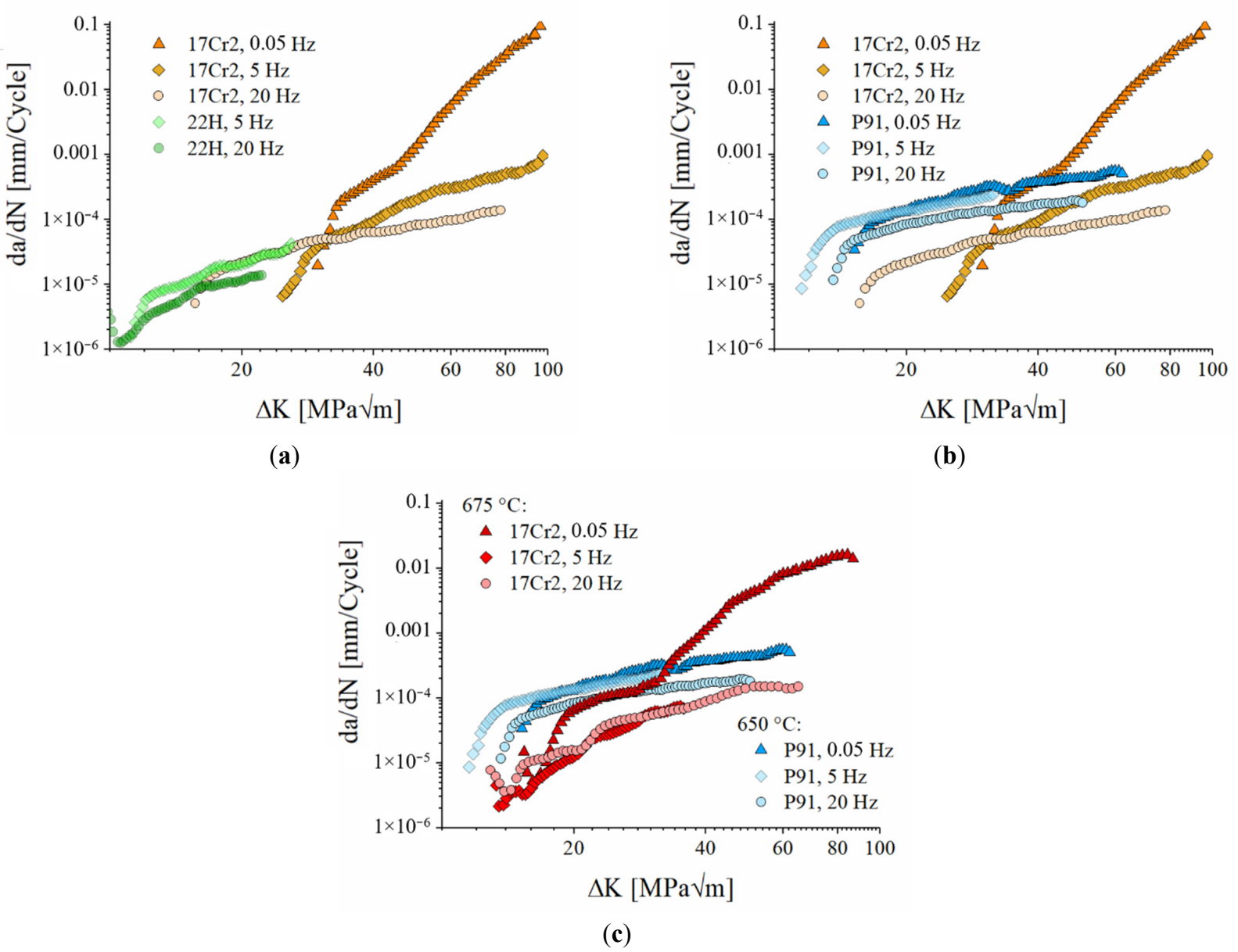
The crack propagation rates at 20 and 5 Hz in HiperFer 17Cr2 were up to ~½ order of magnitude lower for most of the tested stress intensities, which is attributed to the significantly lower Paris prefactor C of HiperFer 17Cr2, despite its higher Paris exponent m compared to P91 (m = 2.41, C = 1.37 × 10⁻⁸ at 5 Hz; m = 1.10, C = 1.07 × 10⁻⁶ at 20 Hz for HiperFer 17Cr2 vs. m = 1.29, C = 2.80 × 10⁻⁶ at 5 Hz; m = 0.92, C = 5.61 × 10⁻⁶ at 20 Hz for P91, Table 2). However, at 5 Hz in the small range of directly comparable stress intensities (48–50 MPa√m), the crack growth rates were approximately similar (cf. Figure 1b). At 0.05 Hz, the crack growth rate of HiperFer 17Cr2 remained below that of P91 up to a crossover point of approximately 38.8 MPa√m, beyond which it exceeded the P91 level. This behavior is directly reflected in the respective Paris parameters, as the substantially lower prefactor C of HiperFer 17Cr2 (C = 2.09 × 10⁻¹⁴ vs. 6.95 × 10⁻⁶ for P91) governs the significantly slower crack growth kinetics at lower ΔK values, while the markedly higher Paris exponent (m = 6.43 vs. 1.07 for P91) drives the accelerated crack growth rate at higher stress intensities, ultimately causing the observed crossover (Table 2).
Table 2. Effect of frequency on fatigue crack growth parameters of HiperFer 17Cr2 (T = 650 and 675 °C), Crofer® 22H and P91 (T = 650 °C).
|
650 °C |
675 °C |
650 °C |
||||||||||
|---|---|---|---|---|---|---|---|---|---|---|---|---|
|
HiperFer 17Cr2 |
Crofer 22H |
HiperFer 17Cr2 |
P91 |
|||||||||
|
Frequency [Hz]: |
m: |
C: |
Range [MPa√m]: |
m: |
C: |
Range [MPa√m]: |
m: |
C: |
Range [MPa√m]: |
m |
C: |
Range [MPa√m]: |
|
0.05 Hz |
6.43 |
2.09 × 10⁻¹⁴ |
34–87 |
- |
5.53 |
1.48 × 10⁻¹² |
32–60 |
1.07 |
6.95 × 10⁻⁶ |
21–60 |
||
|
5 Hz |
2.41 |
1.37 × 10⁻⁸ |
34–88 |
2.20 |
3.04 × 10⁻⁸ |
12–25 |
2.63 |
6.83 × 10⁻⁹ |
22–36 |
1.29 |
2.80 × 10⁻⁶ |
14–31 |
|
20 Hz |
1.10 |
1.07 × 10⁻⁶ |
26–78 |
1.60 |
9.30 × 10⁻⁸ |
13–22 |
1.71 |
1.64 × 10⁻⁷ |
24–50 |
0.92 |
5.61 × 10⁻⁶ |
20–48 |
It is noteworthy to compare the crack propagation behavior of HiperFer 17Cr2 at 675 °C to that of P91 at 650 °C (Figure 1c): Despite the 25 K temperature difference, the stress intensities needed to initiate crack propagation in 17Cr2 at 675 °C were in reasonable correspondence to P91 @ 650 °C, but HiperFer 17Cr2 initially exhibited decreasing crack velocity with increasing stress intensity at all frequencies. The stable crack growth regime at 675 °C was characterized by comparatively low crack propagation rates at lower stress intensities, reflected by the very low Paris prefactor of C = 1.48 × 10⁻¹² at 0.05 Hz, while the markedly high Paris exponent of m = 5.53 indicates a strong increase in crack growth rate with rising ΔK (Table 2 and Table 3). At frequencies of 5 and 20 Hz, the crack propagation rate in the stable crack growth regime of 17Cr2 at 675 °C was up to one order of magnitude lower than that observed for P91 steel at 650 °C.
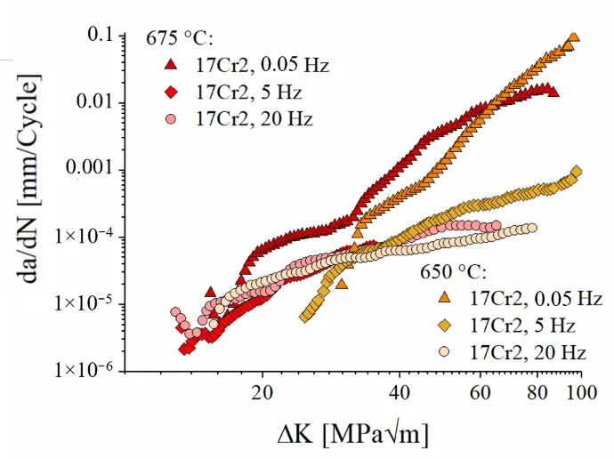
Figure 2a shows the impact of frequency in dependence of temperature at 650 °C and 675 °C in 17Cr2. The crack propagation rates at 5 and 20 Hz at 675 °C do largely correspond to each other and the rate at 20 Hz at 650 °C, while the rates at 0.05 Hz at both the temperatures approximate at stress intensities above 30 MPa√m. It is noteworthy that at 650 °C, the crack propagation initiation value at 5 Hz was 11.57 MPa√m higher than at 20 Hz (Figure 2a: T: 650 °C, ΔKStart @ 20/5 Hz = 15.65/27.22 MPa√m). Such an increase has previously been observed in comparison of fatigue (5–20 Hz) to holding time (e.g., thold = 300 s) tests (e.g., [6]). At 675 °C, the expected increase in stress intensity necessary to initiate crack propagation was observed between 20 and 5 Hz (Figure 2a: T: 675 °C, ΔKStart @ 20/5 Hz = 12.91/14.94 MPa√m). Obviously, much stronger solidification must have taken place in the 5 Hz FCG test at 650 °C.
 |
 |
|
(a) |
(b) |
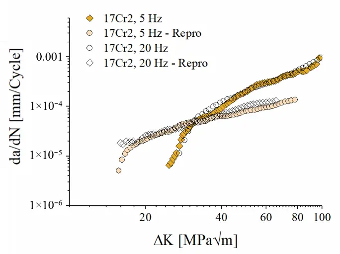
Figure 2. (a) Frequency influence of FCG behavior in HiperFer 17Cr2 at 650 °C and 675 °C; (b) Results of FCG verification tests at 5 and 20 Hz at 650 °C.
3.2. Analysis of the Crack Growth Mechanisms
In comparison to the straight, narrow crack path at 20 Hz, at 5 Hz a more pronounced crack opening and a relatively large plastic zone in front of the crack tip were observed (Figure 3 left). In contrast, at both frequencies, a straight crack path, typical for fatigue crack growth, occurred at 675 °C (Figure 3 right). In order to rule out incorrect execution of the experiment or a deviation in material properties, both the 650 °C FCG tests were repeated. The verification experiments confirmed the strong influence of frequency on the stress intensity necessary for the initiation of crack propagation (Figure 2b: T: 650 °C, ΔKStart, 2nd @ 20/5 Hz = 15.89/24.77 MPa√m).
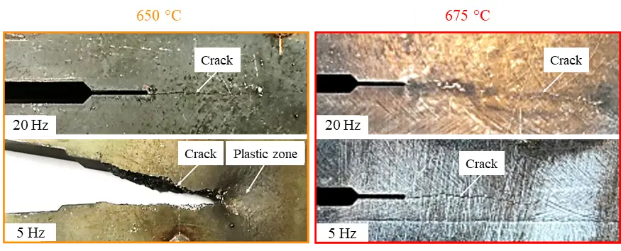
Figure 3. Comparison of FCG crack patterns in the HiperFer 17Cr2 compact tension specimens (left): 5 vs. 20 Hz at 650 °C and (right) at 675 °C.
Microstructural investigation (Figure 4) uncovered strong plastic deformation across several grains in the crack flank area and in front of the crack tip in the case of the 5 Hz test, while minor intragranular plastic deformation occurred in the 20 Hz test only. At 5 Hz, the grains are elongated approximately perpendicular to the crack path. This indicates that grain deformation occurred across the PFZs, as these regions have lower strength than the grain interiors, which are strengthened by Laves precipitates.
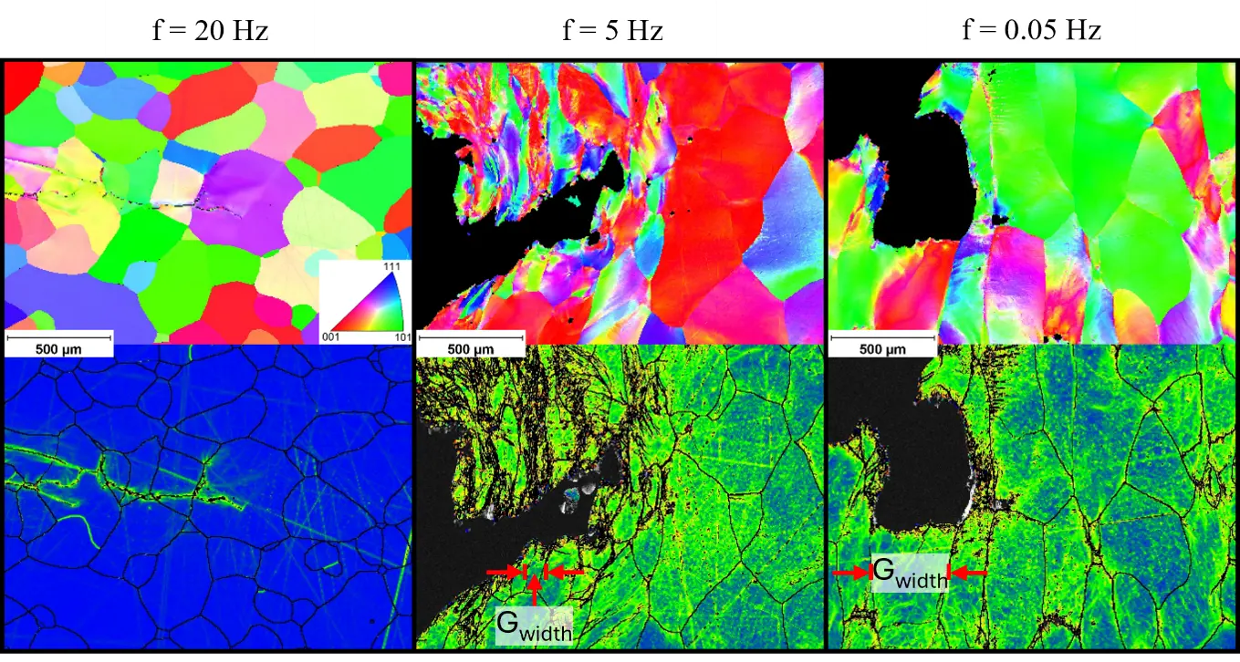
Figure 4. EBSD maps (top) and related misorientation maps (bottom) taken from crack tips in HiperFer 17Cr2/16 compact tension specimens at testing frequencies of 20 Hz, 5 Hz and 0.05 Hz (650 °C).
It is evident that in the 20 Hz experiment, the crack tip is very sharp, whereas it appears significantly blunted in the 5 Hz test, indicating an effective reduction in stress intensity at the crack tip. Strong crack tip blunting was probably caused by easier crack growth along PFZs in comparison to overcoming Laves phase covered grain boundaries. Crack blunting was even more pronounced in the 0.05 Hz specimen. Like encountered at 5 Hz, the grains were elongated approximately perpendicular to the crack path (Figure 4) at 0.05 Hz. However, the width of elongated grains was larger at 0.05 Hz (cf. “Gwidth” in Figure 4). Longer stress relaxation time per cycle may be considered to be the reason for this finding, which is supported by decreased dislocation density (by thermally induced healing) in front of the crack tip.
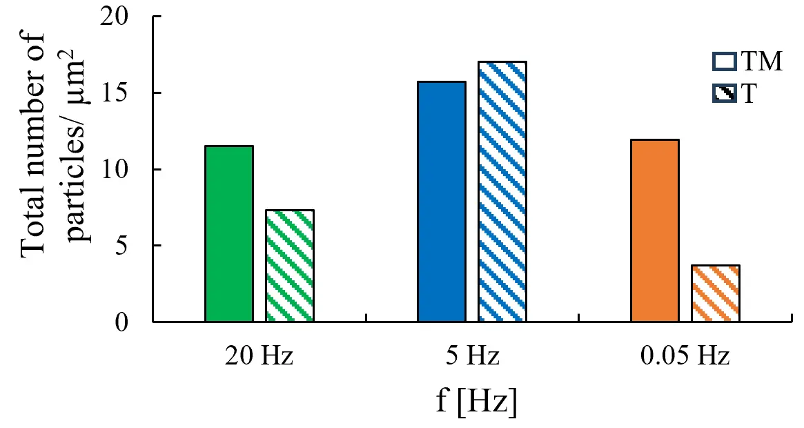
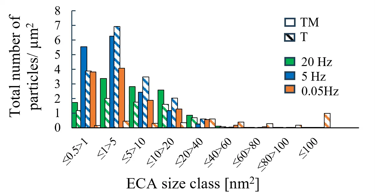
The highest number density of Laves phase particles was observed at 5 Hz (Figure 5 and Figure 6a), while in the 20 Hz experiment, a fewer number of particles was observed. At 5 Hz, the lower cycling frequency provides more time per cycle for nucleation and precipitation compared to 20 Hz, resulting in a higher particle number density that more effectively impedes dislocation motion and thus leads to higher crack initiation resistance. The lowest number density was found at 0.05 Hz. Comparing the particle number density between thermomechanically (TM) and purely thermally (T) loaded 17Cr2 in dependence of frequency, the greatest difference was found at 0.05 Hz, too: Under thermomechanical loading, the number density of particles was approximately three times higher than in purely thermal loading. At 0.05 Hz, the particle size distribution, predominantly in combination with thermomechanical loading, exhibits fine precipitates ranging from 0.5 to >5 nm2, while at 5 and 20 Hz the T and TM size distributions range much closer to each other (Figure 6b). These small particles probably constitute secondary, thermomechanically induced, Laves phase precipitates (cf. Figure 5). Such newly formed precipitates, which actively obstruct crack propagation, were detected in Crofer® 22H—the predecessor of HiperFer 17Cr2, at 20 Hz, too [20]. Furthermore, the particle size distribution (Figure 6b) indicates that some coarsening of the initial particles has occurred, which supports the hypothesis that the smaller particles may constitute newly generated ones. In addition, misorientation mappings (Figure 4) confirm increased dislocation density at and around the crack tip, which can act as nucleation sites, too. At 5 Hz the number of precipitates has been found to be only weakly dependent on the mode of loading (Figure 5 and Figure 6a).
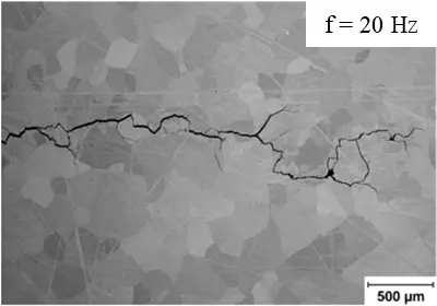
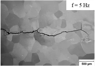
This indicates that the increased stress intensity required for crack initiation in the 5 Hz test did not result from additional particle precipitation, but rather from a complex interplay of existing Laves precipitates, frequency (i.e., time) and temperature dependency, generation of dislocations by cyclic plasticization, and crack tip blunting. However, a precise understanding of these complex interactions requires more experimental investigation. The combined frequency (i.e., time) and temperature dependency is demonstrated by comparing the 5 Hz crack paths at 650 °C and 675 °C: At 650 °C and 5 Hz a comparably rough crack path with strong plastic deformation (cf. Figure 3 left, Figure 4 and Figure 5) is observed, while at 675 °C and 5 Hz the expected straight fatigue crack path occurred (cf. Figure 3 right and Figure 7b).
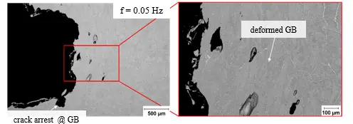
A comparison of the 20 Hz and 5 Hz crack paths at 675 °C revealed more pronounced crack branching at 20 Hz. In contrast, virtually no secondary crack growth away from the main path of propagation was observed at 0.05 Hz. As an example of the suspected underlying mechanism, a secondary crack, arrested and stopped at a grain boundary, is displayed in Figure 7c (left). The higher magnification micrograph (Figure 7c, right) unveils significantly deformed grain boundaries in front of the crack tip. To distinguish between the thermomechanical effect, depending on frequency, and the purely thermal effect, microstructures are compared in Figure 8. Under thermal loading, grain boundary deformation did not occur. PFZ width was largely unaffected by frequency variation and thermomechanical or purely thermal loading (cf. Table 3). In the low frequency fatigued condition (0.05 Hz), the PFZs appeared 9 times wider (3.225 µm) than after pure thermal annealing (0.367 µm). Higher frequency fatigue (5 and 20 Hz) leads to a similar finding. Furthermore, localized recrystallization and subsequent sub-grain formation occurred within the PFZs and the adjacent region (Figure 8). It can be assumed that local grain formation led to “grain refinement” and consequently to an increase in strength.
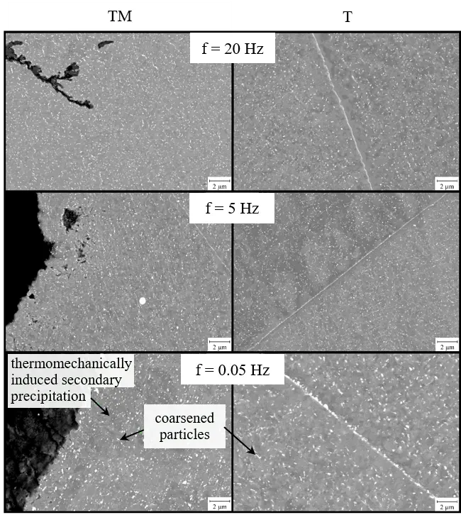
Figure 5. HiperFer 17Cr2 precipitate microstructure in dependency of frequency under combined thermo-mechanical (left) and thermal loading only (right) at 650 °C (TM: Thermo-mechanically loaded, T: Thermally loaded).
 |
 |
|
(a) |
(b) |
Figure 6. (a) Area-specific total number of particles in HiperFer 17Cr2 under thermo-mechanical and thermal loading in dependency of frequency at 650 °C, and (b) corresponding size classification by equivalent circle area (ECA) (TM: Thermo-mechanically loaded, T: Thermally loaded).
 |
 |
|
(a) |
(b) |
 |
|
|
(c) |
|
Figure 7. Micrographs from crack paths in HiperFer 17Cr2 compact tension specimens: Testing frequency of (a) 20 Hz, (b) 5 Hz and (c) 0.05 Hz (675 °C).
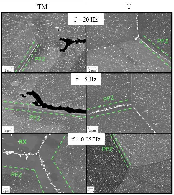
Figure 8. Microstructural evolution of HiperFer 17Cr2 depending on loading frequency under thermo-mechanical (left) and pure thermal exposure (right) at 675 °C.
Table 3. Effect of loading frequency under thermo-mechanical and pure thermal annealing conditions on the average width of the particle-free zones (PFZ) at grain boundaries at 675 °C.
|
f [Hz] |
$$\overline{\bm{W}}$$PFZ (Thermo-Mechanically Loaded) [µm] |
$$\overline{\bm{W}}$$PFZ (Thermally Loaded) [µm] |
|---|---|---|
|
20 |
0.756 |
0.724 |
|
5 |
0.721 |
0.841 |
|
0.05 |
3.225 |
0.367 |
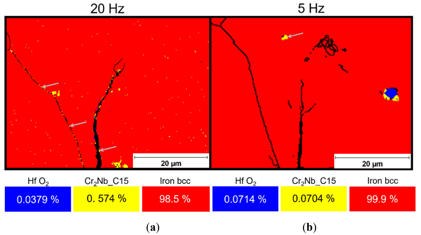
EBSD phase mappings of the crack tips and its vicinities in the 20 and 5 Hz specimens reveal the formation of the cubic C15 Laves phase Cr2Nb (or possibly cubic NbC) (Figure 9). In the 20 Hz test, formation of the C15 Cr2Nb phase was detected in the grain interior and along the crack flank (shown in Figure 9a and marked with arrows), while at 5 Hz the phase was only identified within the grain (displayed in Figure 9b, marked with an arrow). Despite the smaller analyzed area caused by differing effective spatial resolutions, the fraction of C15 Cr2Nb was approximately eight times higher at 20 Hz. Further experimental investigation is required to determine whether this observation is coincidental or whether it reflects an underlying mechanistic effect. The Cr2Nb Laves phase occurs in three polytypes: a cubic C15 (MgCu2-type), a hexagonal C14 (MgZn2-type and a dihexagonal C36 structure) [32]. Under equilibrium conditions, the cubic C15 structure represents the thermodynamically stable phase of Cr2Nb [33]. Significant potential for high-temperature applications is attributed to Cr2Nb because of its high melting point, comparatively low density, excellent creep resistance, satisfactory oxidation behavior, and attractive mechanical strength at elevated temperatures [34,35,36]. This potential is also confirmed by the results of the crack growth investigations performed at 17Cr2 at 675 °C (Figure 2).
EBSD phase mapping in front of the crack tip at 0.05 Hz and 675 °C indicates the formation of C14 Cr2Nb Laves phase at grain boundaries overgrowing the original (Fe, Cr, Si)2(Nb, W) Laves phase and on newly formed sub-grain boundaries under thermomechanical loading conditions (Figure 10 left). In contrast, pure thermal annealing conditions lead to intragranular formation of only the C14 Cr2Nb Laves phase and yield an approximately 11 times smaller fraction of this phase (Figure 10 right). The C14 Cr2Nb phase is described as a metastable phase [32,37]. The existence of the Cr2Nb phase is controversially discussed in the literature and was summarized in [37]. According to [38], non-equilibrium conditions facilitate the formation of the C14 Cr2Nb phase. These findings may indicate a pronounced chemical imbalance, resulting from strongly differing local concentrations of the elements caused by pipe diffusion along newly formed sub-grain boundaries (Figure 10 left), which leads to the formation of the C14 Cr2Nb Laves phase. It may be considered that the formation of C14 Cr2Nb was further promoted by thermomechanical stress, as pure thermal annealing results in approximately 11 times fewer Laves phase precipitates.
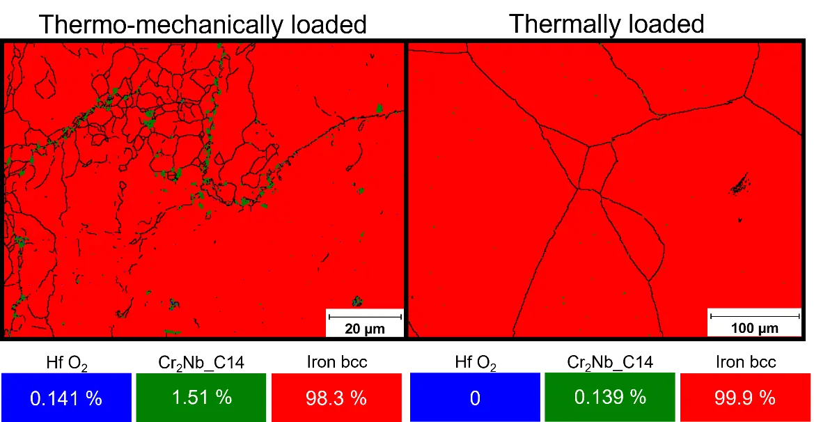
Figure 10. EBSD phase maps and grain boundaries (>3°) in front of the crack tip at 0.05 Hz and 675 °C under combined thermo-mechanical (left) and thermal loading only (right).
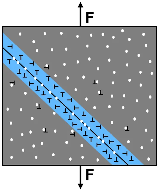
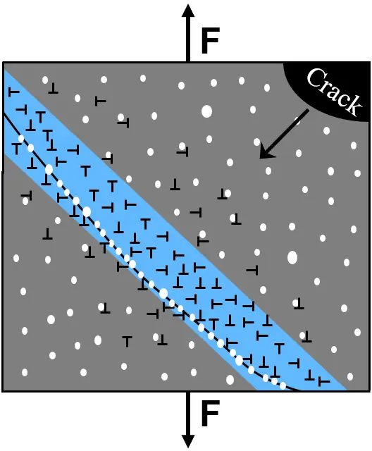
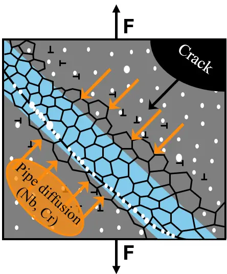
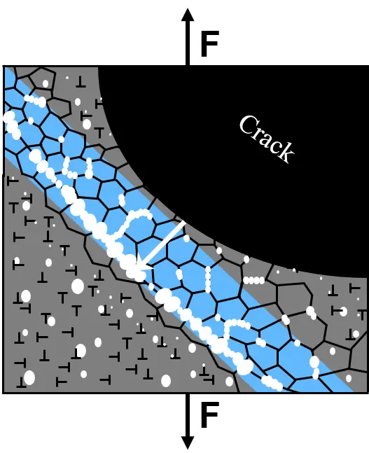
The complex crack propagation mechanisms at 675 °C/0.05 Hz are summarized schematically in Figure 11.
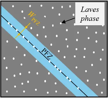
Figure 11a illustrates the initial microstructure comprising a Laves phase particle strengthened matrix, Laves phase covered Gbs, and PFZs along these. Under cyclic loading, dislocations form in the PFZs and their near vicinity (Figure 11b) at an early stage. As the sharp pre-crack propagates, local matrix distortion increases, resulting in a further rise in dislocation density, consequently leading to elevated internal stress (arising from high dislocation density) and leading to HAGb curvature. This suggests that the local matrix strength temporarily undermatched the critical energy (or driving force) necessary for grain boundary movement. In addition, beginning coarsening of primary intragranular Laves phase precipitates was observed (Figure 11c). The combination of high dislocation density and elevated temperature (675 °C) promotes thermally activated dislocation climb and cross-slip, thereby enabling local dynamic recovery within the PFZs, which leads to dislocation rearrangement and progressive formation of sub-grains (Figure 11d). The newly formed sub-grain boundaries (SGb) provide fast diffusion pathways for pipe diffusion. EBSD phase mapping suggests that Nb and Cr (Figure 10) were preferentially transported towards the grain boundary (GB). Presumably, the significantly higher matrix concentration of Cr compared to Nb led to a higher Cr flux along this diffusion pathway, resulting in pronounced local compositional imbalance at the grain boundary, ultimately promoting the formation of inter-granular and inter-subgranular C14 Cr2Nb Laves precipitates. As crack propagation progresses, pronounced deformation at the crack tip results in a further increase in dislocation density. The accumulated dislocations provide heterogeneous nucleation sites for the formation of fine secondary Laves phase precipitates (Figure 11e), which actively obstruct crack growth. Extensive cyclic plasticity at the crack tip leads to the development of a pronounced plastic zone, resulting in crack-tip blunting along the entire crack front. The associated crack-tip stress relaxation and plastic zone shielding reduce local stress concentrations and effectively lower the effective driving force for continued crack propagation.
 |
 |
 |
|
|
(a) |
(b) |
(c) |
|
 |
 |
||
|
(d) |
(e) |
||
Figure 11. Schematic illustration of the crack growth mechanisms at 675 °C/0.05 Hz: (a) Initial microstructure. (b) Increase in dislocation density within the PFZ under cyclic loading. (c) Further generation of dislocations in the PFZ leading to grain boundary curvature, accompanied by initial coarsening of Laves phase particles. (d) Formation of sub-grains within the PFZ (dynamic recovery). Enhanced pipe diffusion of Nb and Cr along newly formed sub-grain boundaries, followed by further coarsening of the Laves phase particles at grain and sub-grain boundary (e). Formation of secondary precipitates in high dislocation density areas (resulting from matrix distortion in the crack vicinity) accompanied by continued coarsening of intragranular primary precipitates.
To summarize this, the reason for the complex frequency (i.e., time)/temperature response lies in the “reactive” microstructure of HiperFer steel and is argued to be interaction of various key factors for dynamic strengthening in front of the propagating crack tip, like (1) generation of dislocations by cyclic plasticization, (2) thermally induced healing of dislocations, (3) dynamic precipitation of secondary and (4) coarsening of primary Laves phase particles as well as (5) plastically induced sub-grain formation. Furthermore, (6) coverage of grain and (newly formed) sub-grain boundaries and (newly formed) dislocations by secondary Laves phase particles plays a role. To complicate things even more, most of these parameters are interrelated and, for this reason, are subject to future investigation.
4. Conclusions
The crack propagation behavior of the novel fully ferritic high-chromium steel HiperFer 17Cr2 was investigated at temperatures of 650 °C and 675 °C at loading frequencies of 20, 5, and 0.05 Hz, motivated by the demand for advanced high-temperature materials capable of improving the thermodynamic efficiency of future thermal energy conversion systems and reducing associated greenhouse gas emissions. For benchmarking purposes, the widely used 9Cr-1Mo-V-Nb ferritic-martensitic steel P91 was examined in parallel at 650 °C. Complementary microstructural analyses were performed to characterize the frequency- and temperature-dependent damage mechanisms. The results lead to the following conclusions:
4.1. Fatigue Crack Propagation Behavior: HiperFer 17Cr2 vs. Crofer® 22H vs. P91
-
-
The fatigue crack propagation resistance of HiperFer 17Cr2 is significantly improved relative to its predecessor alloy, Crofer® 22H (Figure 1a).
-
-
At 650 °C, the stress intensity required for the initiation of crack propagation was substantially higher in HiperFer 17Cr2 than in P91 at all the tested frequencies (Figure 1b). The crack growth rate da/dN was up to approximately half an order of magnitude lower at 20 and 5 Hz, and remained lower at 0.05 Hz up to a stress intensity of approximately 36 MPa√m.
-
-
Comparison of P91 at 650 °C to HiperFer 17Cr2 at 675 °C (Figure 1c): the stress intensity needed for the initiation of crack propagation was approximately equivalent at 20 and 5 Hz in both the steels, but higher at 0.05 Hz in the case of 17Cr2. At 20/5 Hz, the crack growth rate was up to one order of magnitude lower in 17Cr2 MPa√m in the stable crack growth regime.
4.2. Microstructural Mechanisms in HiperFer 17Cr2
-
-
At 650 °C/20 Hz, a reproducible anomaly in the frequency dependency was observed: The threshold stress intensity for crack initiation was approximately 12 MPa√m lower than at 5 Hz, with the associated plastic zone being more comparable to that observed under hold-time loading (superimposed creep) conditions [6]. This behavior is attributable to elevated intragranular dislocation density, which helps deflect crack propagation along PFZs through pronounced work hardening and results in significant crack-tip blunting and a consequent reduction in the effective driving force for crack propagation.
-
-
At 650 °C/0.05 Hz, additional thermo-mechanically induced, secondary Laves phase precipitates were identified in the crack-tip region.
-
-
At 675 °C/20 and 5 Hz, a sharp crack morphology with pronounced crack branching was observed, whereas a widened, blunted crack tip prevailed at 0.05 Hz.
-
-
At 675 °C/20 and 5 Hz, the thermodynamically stable C15 Laves phase was identified, while the 0.05 Hz condition promoted the formation of a thermodynamically metastable C14 Laves phase at HAGBs and newly formed SGBs.
-
-
At 675 °C/0.05 Hz, a sequential damage and hardening mechanism was found to govern crack propagation: Cyclic loading initially induces dislocation accumulation in the PFZs, promoting dynamic recovery, sub-grain formation, and pipe diffusion-assisted redistribution of Cr and Nb towards grain and sub-grain boundaries, ultimately facilitating the formation of the metastable C14 Cr2Nb Laves phase at these. The newly formed, fine secondary Laves phase precipitates act as effective obstacles to crack growth, while extensive crack-tip plasticity results in crack-tip blunting, reducing the local stress concentration and lowering the effective driving force for crack propagation.
4.3. Concluding Remarks
The present crack propagation study demonstrates that HiperFer 17Cr2 exhibits sufficient fatigue crack propagation resistance to permit continuous service at 675 °C under high-cycle fatigue loading in the frequency range from 5 to 20 Hz. To ensure the safe use of 17Cr 2, an investigation into crack propagation properties in steam is recommended. At low frequency (0.05 Hz), continuous operation at temperatures exceeding 650 °C seems not to be feasible due to the complex interplay of competing microstructural and damage mechanisms. However, the current findings indicate that short-term temperature excursions to 675 °C may be tolerable, but continued service necessitates compositional adaption. Further investigation is required to develop a comprehensive mechanistic understanding and will be conducted within the framework of a subsequent DFG-funded research project.
Acknowledgments
The authors would like to express their gratitude to the former colleagues of Forschungszentrum Jülich GmbH for their continuous contributions to HiperFer alloy development. The support of B. Werner and H. Reiners in mechanical testing, V. Gutzeit and J. Bartsch in sample preparation, and E. Wessel and D. Grüner for microstructural investigation of this specific study is greatly appreciated.
Author Contributions
Conceptualization: T.F. and B.K.; Methodology: T.F.; Software: T.F.; Validation: B.K.; Formal Analysis: T.F. and B.K.; Investigation: T.F. and B.K.; Resources: B.K.; Data Curation: T.F. and B.K.; Writing—Original Draft Preparation: T.F.; Writing—Review & Editing, B.K.; Visualization: T.F. and B.K.; Supervision: B.K.; Project Administration: B.K.; Funding Acquisition: B.K.
Ethics Statement
Not applicable.
Informed Consent Statement
Not applicable.
Data Availability Statement
Not available.
Funding
Parts of this research were funded by Deutsche Forschungsgemeinschaft (DFG) under grant number AOBJ 671123 and the Germany Federal Ministry for Economic Affairs and Energy (BMWE) under grant number FKZ 03ET7024A.
Declaration of Competing Interest
The authors declare that they have no known competing financial interests or personal relationships that could have appeared to influence the work reported in this paper.
References
-
Santos JJCS, Palacio JCE, Reyes AMM, Carvalho M, Freire AJR, Barone MA. Advances in Renewable Energies and Power Technologies. In Solar and Wind Energies; Elsevier: Amsterdam, The Netherlands, 2018; pp. 373–402. [Google Scholar]
-
Hoschmidt B, Alexopoulos S, Göttsche J, Sauerborn M, Kaufhold O. High Concentration Solar Collectors. In Comprehensive Renewable Energy; Elsevier: Amsterdam, The Netherlands, 2012; pp. 167–207. [Google Scholar]
-
Thess A, Hoffschmidt B, Giuliano S, Trieb F. Wärmespeicherkraftwerke—Positionspapier des DLR Zum Umbau von Kohlekraftwerken auf Einen CO2-Neutralen Betrieb, Deutsches Zentrum für Luft- und Raumfahrt. 2019. Available online: https://www.dlr.de/de/medien/publikationen/sonstige-publikationen/positionspapiere/waermespeicherkraftwerke/@@download/file (accessed on 26 June 2026).
-
Agora Energiewende. Flexibility in Thermal Power Plants—With a Focus on Existing Coal-Fired Power Plants; Agora Energiewende: Berlin, Germany, 2017. [Google Scholar]
-
Holdsworth S. Creep-Fatigue Crack Growth in Power Plant Steels. Trans. Indian Inst. Met. 2016, 69, 353–358. DOI:10.1007/s12666-015-0752-0 [Google Scholar]
-
Fischer T, Kuhn B. Frequency and hold time influence on crack growth behavior of a 9–12% Cr ferritic martensitic steel at temperatures from 300 °C to 600 °C in air. Int. J. Fatigue 2018, 112, 165–172. DOI:10.1016/j.ijfatigue.2018.03.012 [Google Scholar]
-
Ploumen P, Stienstra G, Kamphuis H. Reduction of CO2 emissions of coal fired power plants by optimizing steam water cycle. Energy Procedia 2011, 4, 2074–2081. DOI:10.1016/j.egypro.2011.02.090 [Google Scholar]
-
Abe F. Research and Development of Heat-Resistant Materials for Advanced USC Power Plants with Steam Temperatures of 700 °C and Above. Engineering 2015, 1, 211–224. DOI:10.15302/J-ENG-2015031 [Google Scholar]
-
Viswanathan R, Bakker W. Materials for Ultrasupercritical Coal Power Plants—Boiler Materials: Part 1. J. Mater. Eng. Perform. 2001, 10, 81–95. DOI:10.1361/105994901770345394 [Google Scholar]
-
Fournier B, Dalle F, Sauzay M, Longour J, Salvi M, Caës C, et al. Comparison of various 9–12%Cr steels under fatigue and creep-fatigue loadings at high temperature. Mater. Sci. Eng. A 2011, 528, 6934–6945. DOI:10.1016/j.msea.2011.05.046 [Google Scholar]
-
Führer U, Aktaa J. Modeling the cyclic softening and lifetime of ferritic-martensitic steels under creep-fatigue loading. Int. J. Mech. Sci. 2018, 136, 460–474. DOI:10.1016/j.ijmecsci.2017.12.042 [Google Scholar]
-
Batista MN, Marinelli MC, Hereñú S, Alvarez-Armas I. The role of microstructure in fatigue crack initiation of 9–12%Cr reduced activation ferritic–martensitic steel. Int. J. Fatigue 2015, 72, 75–79. DOI:10.1016/j.ijfatigue.2014.11.006 [Google Scholar]
-
Zhao Y, Liu HL, Wei LL, Chen LQ. An overview on the novel heat-resistant ferritic stainless steels. Tungsten 2023, 5, 467–480. DOI:10.1007/s42864-022-00171-4 [Google Scholar]
-
Wagner R, Czempik E. Konservierung von Kesselanlagen und Turbinen mit dem grenzflächenaktiven Stoff Octadecylamin. VGB Powertech 2014, 3, 48–51. Available online: https://pascal-francis.inist.fr/vibad/index.php?action=getRecordDetail&idt=28263662 (accessed on 26 June 2026).
-
Quadakkers WJ, Piron-Abellan J, Shemet V, Singheiser L. Metallic interconnectors for solid oxide fuel cells—A review. Mater. High Temp. 2003, 20, 115–127. DOI:10.3184/096034003782749071 [Google Scholar]
-
Kimura A, Kasada R, Kohyama A, Tanigawa H, Hirose T, Shiba K, et al. Recent progress in US–Japan collaborative research on ferritic steels R&D. J. Nucl. Mater. 2007, 367–370, 60–67. DOI:10.1016/j.jnucmat.2007.03.013 [Google Scholar]
-
Shibuya M, Toda Y, Sawada K, Kushima H, Kimura K. Effect of nickel and cobalt addition on the precipitation-strength of 15Cr ferritic steels. Mater. Sci. Eng. A 2011, 528, 5387–5393. DOI:10.1016/j.msea.2011.03.088 [Google Scholar]
-
Pandey C, Mahapatra MM, Kumar P, Saini N. Some studies on P91 steel and their weldments. J. Alloys Compd. 2018, 743, 332–364. DOI:10.1016/j.jallcom.2018.01.120 [Google Scholar]
-
Kuhn B, Talik M, Niewolak L, Zurek J, Hattendorf H, Ennis PJ, et al. Development of high chromium ferritic steels strengthened by intermetallic phases. Mater. Sci. Eng. A 2014, 594, 372–380. DOI:10.1016/j.msea.2013.11.048 [Google Scholar]
-
Fischer T, Kuhn B. Active Crack Obstruction Mechanisms in Crofer® 22H at 650 °C. Materials 2022, 15, 6280. DOI:10.3390/ma15186280 [Google Scholar]
-
Kuhn B, Talik M, Fischer T, Fan X, Yamamoto Y, Lopez Barrilao J. Science and Technology of High Performance Ferritic (HiperFer) Stainless Steels. Metals 2020, 10, 463. DOI:10.3390/met10040463 [Google Scholar]
-
Kuhn B, Talik M. HiperFer—High Performance Ferritic Steels. In Proceedings of the 10th Liége Conference on Materials for Advanced Power Engineering, Liége, Belgium, 14–17 September 2014; pp. 264–273. [Google Scholar]
-
Fan X, Kuhn B, Pöpperlová J, Bleck W, Krupp U. Compositional Optimization of High-Performance Ferritic (HiperFer) Steels—Effect of Niobium and Tungsten Content. Metals 2020, 10, 1300. DOI:10.3390/met10101300 [Google Scholar]
-
Xu H, Si S, Li Y, Liu X, Li W, Jiang C, et al. The effect of Laves phase on heavy-ion radiation response of Nb-containing FeCrAl alloy for accident-tolerant fuel cladding. Fundam. Res. 2022, 2, 437–446. DOI:10.1016/j.fmre.2022.01.028 [Google Scholar]
-
Liu H, Wei L, Ma M, Zheng J, Chen L, Misra RDK. Laves phase precipitation behavior and high-temperature strength of W-containing ferritic stainless steels. J. Mater. Res. Technol. 2020, 9, 2127–2135. DOI:10.1016/j.jmrt.2019.12.043 [Google Scholar]
-
Kuhn B, Talik M. Heat Treatment of High-Performance Ferritic (HiperFer) Steels. Materials 2023, 16, 3500. DOI:10.3390/ma16093500 [Google Scholar]
-
Pöpperlová J, Fan X, Kuhn B, Bleck W, Krupp U. Impact of Tungsten on Thermomechanically Induced Precipitation of Laves Phase in High Performance Ferritic (HiperFer) Stainless Steels. Appl. Sci. 2020, 10, 4472. DOI:10.3390/app10134472 [Google Scholar]
-
Fan X, Kuhn B, Pöpperlová J, Bleck W, Krupp U. Thermomechanically Induced Precipitation in High-Performance Ferritic (HiperFer) Stainless Steels. Appl. Sci. 2020, 10, 5713. DOI:10.3390/app10165713 [Google Scholar]
-
Ennis PJ, Czyrska-Filemonowicz A. Recent advances in creep-resistant steels for power plant applications. Sadhana 2003, 28, 709–730. DOI:10.1007/BF02706455 [Google Scholar]
-
ASTM E647-11; Standard Test Method for Measurement of Fatigue Crack Growth Rates. ASTM International: West Conshohocken, PA, USA, 2011. [Google Scholar]
-
Paris P, Erdogan F. A critical analysis of crack propagation laws. J. Basic Eng. 1963, 85, 528–533. DOI:10.1115/1.3656900 [Google Scholar]
-
Li K, Li S, Zhao S, Zhong H, Xue Y, Fu H. Phase stability of the laves phase Cr2Nb in a two-phase Cr-Cr2Nb alloy. Acta Metall. Sin. 2013, 26, 687–692. DOI:10.1007/s40195-013-0140-x [Google Scholar]
-
Hong S, Fu CL. Phase stability and elastic moduli of Cr2Nb by first-principles calculations. Intermetallics 1999, 7, 5–9. DOI:10.1016/S0966-9795(98)00005-3 [Google Scholar]
-
Kazantzis AV, Aindow M, Jones IP, Triantafyllidis GK, De Hosson JTM. The mechanical properties and the deformation microstructures of the C15 Laves phase Cr2Nb at high temperatures. Acta Mater. 2007, 55, 1873–1884. DOI:10.1016/j.actamat.2006.10.048 [Google Scholar]
-
Takasugi T, Yoshida M, Hanada S. Deformability improvement in C15 NbCr2 intermetallics by addition of ternary elements. Acta Mater. 1996, 44, 669–674. DOI:10.1016/1359-6454(95)00174-3 [Google Scholar]
-
Li K, Li S, Xue Y, Fu H. Microstructure characterization and mechanical properties of a Laves-phase alloy based on Cr2Nb. Int. J. Refract. Met. Hard Mater. 2013, 36, 154–161. DOI:10.1016/j.ijrmhm.2012.08.009 [Google Scholar]
-
Schmetterer C, Khvan A, Jacob A, Hallstedt B, Markus T. A New Theoretical Study of the Cr-Nb System. J. Phase Equilib. Diffus. 2014, 35, 434–444. DOI:10.1007/s11669-014-0313-y [Google Scholar]
-
Förner A, Vollhüter J, Hausmann D, Arnold C, Felfer P, Neumeier S, et al. Nanostructuring of Nb-Si-Cr Alloys by Electron Beam Melting to Improve the Mechanical Properties and the Oxidation Behavior. Met. Mater. Trans. A 2022, 53, 240–249. DOI:10.1007/s11661-021-06516-x [Google Scholar]