
Residual Stress Characteristics in Additive/Subtractive Hybrid Manufacturing: A Review
Residual Stress Characteristics in Additive/Subtractive Hybrid Manufacturing: A Review
Shuaiyuan Yan 1,2 Yuying Yang 1,2,* Shuoshuo Qu 3,4,* Yongqian Yang 1,2 Zhaoqiang Chen 1,2 Yang Wu 1,2 Antong Ouyang 1,2 Chonghai Xu 1,2 Guoqing Wang 5 Chuanjia Qi 5 Bin Sun 5 Jianghan Guo 5 Teng Gao 6 Xiaoming Wang 6
Received: 02 May 2026 Revised: 03 June 2026 Accepted: 22 June 2026 Published: 01 July 2026

© 2026 The authors. This is an open access article under the Creative Commons Attribution 4.0 International License (https://creativecommons.org/licenses/by/4.0/).
1. Introduction
The process of metal additive manufacturing (AM) is confronted with considerable constraints in attaining high-precision part formation and surface quality control, thereby hindering the direct production of parts with high accuracy. Conversely, machining processes founded upon the principle of material removal have been demonstrated to exhibit superior performance with regard to part forming precision and surface quality control, coupled with excellent stability [1,2,3]. Consequently, additive/subtractive hybrid manufacturing (A/SHM) signifies a highly integrated rapid direct forming process that combines AM with subtractive manufacturing (SM) technologies. The technology utilizes the benefits of AM, including ease of configuration, automation control, high forming efficiency, and superior material utilization, while leveraging the characteristics of SM, such as high forming precision and excellent surface quality. This approach facilitates the efficient, high-precision, and high-performance rapid direct forming of metal components [4,5,6,7]. It is evident that A/SHM processes can be categorized into two distinct forms: namely, cross-cooperative and process-separated. In cross-cooperative processes, AM and SM techniques are alternated, thereby effectively reducing cumulative errors during forming and enhancing part dimensional accuracy. However, machining under thermal conditions has been shown to cause tool softening, leading to accelerated wear and reduced tool life. Furthermore, in instances where components necessitate high forming precision, the process of hot machining gives rise to dynamic thermal coupling, which, in turn, results in workpiece deformation. Subsequent finishing operations are necessary to ensure the final dimensional accuracy of the part. The process of separation entails the machining of the net-shaped blank produced by AM, with the objective of achieving components that meet the requisite precision standards. It has been established that, owing to considerable heat accumulation during the process of deposition, a period of cooling to a steady state is required, thus resulting in lower overall forming efficiency. However, machining at room temperature has been demonstrated to enable higher precision in a single forming operation [8,9,10]. However, the technical systems for A/SHM currently lack comprehensive establishment. In conclusion, A/SHM technologies and equipment for high-performance, complex components are currently in their infancy. Fundamental issues such as component design methodologies, forming mechanisms, process planning for A/SHM, selection of process conditions, and intelligent development require systematic research [7,11,12]. A/SHM technology signifies a paradigm shift in the domain of AM, transcending the constraints imposed by limitations in part size and processing quality. This technology offers a novel methodology for fabricating complex parts that are otherwise challenging to realize with conventional SM techniques [13,14]. Figure 1 shows the overall research framework of this paper.
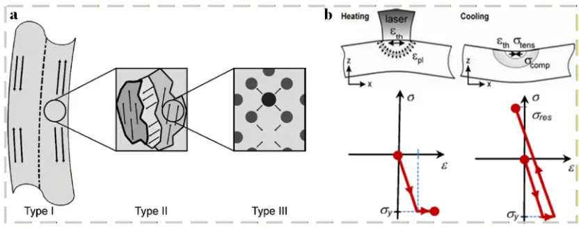
Residual stress (RS) is defined as the stress that remains within a material even when no external load is applied, after the material has reached equilibrium with its environment [15,16,17,18,19]. Figure 2 shows that the classification of RS can be categorized into three distinct types, namely Type I, Type II, and Type III, based on the underlying scale of their origin. Type I RS is related to the size of the part and is prone to causing deformation; Type II RS is micro-stress between grains; Type III RS originates from atomic-scale mismatch. Due to the limitations of measurement techniques, Type II and Type III RS are widespread yet difficult to measure; therefore, this paper primarily focuses on Type I RS. Currently, most research focuses on the stress direction at the substrate-part connection [20,21,22]. Different processes introduce different RS, with laser processes introducing more due to large thermal gradients, which can lead to part deformation and micro-cracks, thereby restricting mechanical performance. RS can reduce load-bearing capacity, fatigue life, promote crack propagation, and change corrosion behavior, accelerating stress corrosion. However, RS also has benefits, such as the compressive stress on the surface of glass, which can increase loading resistance and prevent crack propagation [23,24,25,26]. With regard to the mechanism of RS generation, there are mainly two models for the generation mechanism of RS: the temperature gradient mechanism (TGM) and the remelting and solidification stage model. In the TGM, a high-energy heat source rapidly heats the material, forming a steep temperature gradient; the material’s expansion is restricted by the surroundings, generating elastic compressive strain and causing bending. During cooling, the contraction is restricted, forming RS in the heated area, which is balanced by the compressed area. This mechanism does not require material melting. The remelting and solidification stage model is applicable to A/SHM: the material undergoes remelting and solidification again, and the cooling contraction is partially restricted by the previously deposited material, thus forming RS in the newly deposited layer [24]. The advent of topology optimization (TO) algorithms has rendered the utilization of these algorithms for the optimization of manufacturing processes with the objective of reducing RS a viable proposition [27,28]. Although RS can be relieved through post-processing heat treatment (HT), generating significant RS during the process can cause excessive deformation, leading to production failures or errors. Additional HT further increases production time and costs for an already high-cost process [7,19,29,30,31,32,33]. Therefore, understanding and controlling RS is of great significance for process design, material selection, and process optimization [34,35,36,37,38,39,40], thereby promoting technological progress and product quality in high-precision industries such as aerospace, biomedicine, and automotive manufacturing [41,42,43,44]. Subsequent chapters of this study will thoroughly discuss the influencing factors of RS, measurement methods, as well as the characterization and process control optimization of RS in A/SHM.
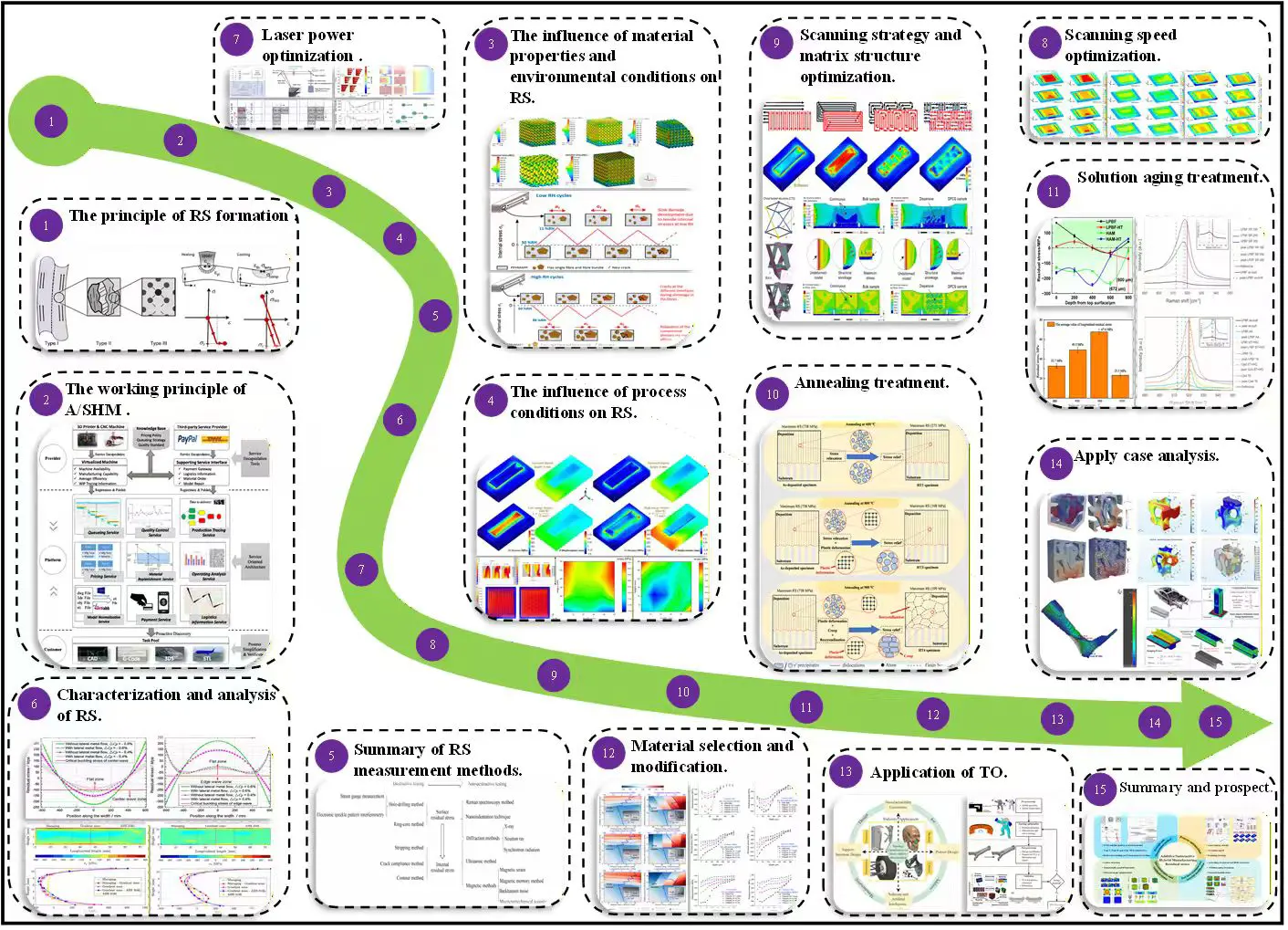
This paper reviews the integration of RS formation mechanisms and measurement methods in A/SHM. It achieves differentiated innovation in three aspects: research scope, argument structure, and frontier assessment. In terms of the research subject, it focuses on the unique process characteristics of A/SHM, discussing the mechanisms by which specific operations, such as interlayer milling, thermo-mechanical coupling, and intermittent cooling, induce additional stresses. Logically, it constructs a closed-loop framework encompassing stress generation–evolution patterns–detection and characterization–process control. In content, grounded in the development trends of next-generation manufacturing, it systematically organizes data-driven closed-loop control technologies that integrate multi-source sensor monitoring, finite element (FE) analysis, and ML-based coupled modeling.
This study employed a systematic literature search strategy, covering both Chinese and English databases, including Web of Science, ScienceDirect, and CNKI. The primary search terms were Additive/subtractive hybrid manufacturing or Combined additive and subtractive machining, and Residual stress or Thermal stress, supplemented with keywords such as Layer milling, Interlayer machining, and Thermo-mechanical coupling. The time span covered 2012 to 2026. Eligible studies included peer-reviewed articles on experimental, simulation, and review research related to RS in A/SHM processes, focusing on the causes, distribution patterns, process control, and intelligent monitoring of RS. Duplicates, papers with identical experimental data, patents, and low-quality publications were excluded. Preference was given to Q1/Q2 English journals and core Chinese sources, such as those indexed in the Peking University Core Journals. Initially, 487 articles were retrieved, and 296 were finally included.
2. Fundamental Principles and Processes of Additive/Subtractive Hybrid Manufacturing
2.1. Additive Manufacturing Technology and Subtractive Manufacturing Technology
The core principle of AM is layer-by-layer fabrication and incremental buildup. First, a 3D CAD model is sliced into 2D cross-sections according to a predefined layer thickness, generating CNC code for processing paths. Then, an energy source deposits or solidifies material layer by layer, transforming the digital model into a physical object [45,46,47]. Figure 3a–c shows the process flow. This technology enables the production of complex geometries with high material utilization and design flexibility, eliminating the need for cutting tools and fixtures, thus achieving freeform manufacturing. It is particularly suitable for high-precision applications in aerospace, biomedical, and automotive industries [48,49]. However, thermal history often leads to defects such as RS, porosity, surface roughness, shrinkage, and deformation, which negatively affect mechanical properties and dimensional accuracy [50,51]. These defects are influenced by process parameters including layer thickness, laser power, scanning strategy, and build orientation [52,53]. In recent years, the intelligent development of AM has become a major research focus, driven by continuous advancements in artificial intelligence (AI) technology [54]. Figure 3d shows machine learning (ML) applications. The current status of ML-assisted AM research is as follows: At the macro-scale, efforts focus on geometric prediction and parameter optimization for single-track deposition due to its computational efficiency and ease of monitoring. However, extension to multi-layer and multi-track processes remains a challenge. Monitoring thin-walled components is relatively simple, whereas complex structures require multi-angle vision and multidimensional input data. At the meso- and micro-scales, research centers on pore formation and evolution, as well as the impact of microstructure on mechanical properties and fatigue life. ML integrated with thermal imaging, acoustic emission, and other data enables real-time defect monitoring, yet challenges persist in detecting micrometer-scale pores and addressing signal lag. Fatigue life prediction is transitioning from purely data-driven approaches to hybrid models that combine physical mechanisms with machine learning to balance limited data availability and computational cost. Current limitations include poor data availability and quality, weak cross-material generalization, difficulties in synchronizing real-time sensing with large data volumes, and insufficient model scalability and interpretability. Addressing these challenges involves strategies such as hybrid datasets, transfer learning, advanced sensing technologies, edge computing, model compression, and physics-informed models [55,56,57]. Over the past two decades, AM technology has advanced at a remarkable pace. Its applications span a wide range of fields, including aerospace, biomedical engineering, bridge construction, and automotive manufacturing, and have yielded significant results [58,59]. For instance, Airbus’s A350 cable bracket, designed using topology optimization and additive manufacturing, integrates 30 parts and reduces weight by 30% [60,61,62]. Wire + arc additive manufacturing (WAAM) was used to construct the world’s first metal bridge [63]. In biomedicine, it enables customized cardiovascular stents, titanium mesh implants [64,65], and lattice structures that reduce MRI artifacts [66]. In the automotive sector, FDM processes have also been demonstrated for other automotive components, such as bumpers and pillar trim [67,68].
Subtractive manufacturing is based on the principle of material removal, progressively eliminating excess material layer by layer using cutting tools or energy beams. By leveraging CNC technology, CAD models are converted into machining paths to achieve high-precision processing [69,70]. Figure 4 shows the process flow. Its advantages include micrometer-level accuracy and low surface roughness, making it suitable for metals, ductile materials, and composites, enabling the fabrication of complex geometries [71,72]. Compared with additive-manufactured parts, subtractively manufactured parts exhibit superior mechanical properties after plastic deformation and heat treatment. With mature processes, well-developed equipment, and a robust supply chain, it is widely applied in aerospace, biomedical, and automotive industries. However, drawbacks include significant material waste, high costs, environmental concerns, multiple processing steps required for complex parts, and increased expenses due to tool wear and maintenance [73,74]. The relationship among processing, structure, and performance remains incompletely understood, posing one of the key research challenges [75,76]. In recent years, the intelligent development of SM has become a key trend in its evolution, driven by continuous advancements in intelligent manufacturing technologies. As technology continues to advance, SM techniques will become more intelligent and integrated, and the development of ML models in related fields will become increasingly diverse [77,78,79]. SM technologies have reached a state of relative maturity, with their technical and commercial systems being widely used in the aerospace, biomedical, and automotive manufacturing industries, among others [80,81]. In the aerospace industry, for example, milling, drilling, and cutting techniques are commonly used to process sandwich composites. Both symmetrical and asymmetrical sandwich composites have been used in the manufacture of aircraft and spacecraft [82,83]. CNC precision machining is used to produce custom-fit artificial joints and dental implants to ensure seamless integration with bone tissue. Multiphoton polymerization micro/nanofabrication is used to manufacture microneedle arrays and bio-compatible micro-scaffolds which structures that have significant applications in drug delivery and tissue engineering. Concurrently, laser selective etching technology plays a pivotal role in microfluidic fabrication [84,85]. In automotive manufacturing, laser welding technology is employed for joining body steel panels. By optimizing material thickness distribution, such as using high-strength steel in critical areas and thin aluminum sheets in non-critical sections, it achieves weight reduction while maintaining safety [86,87].
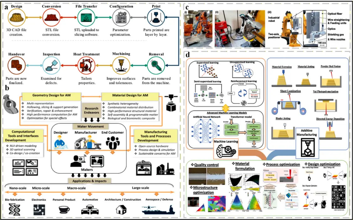
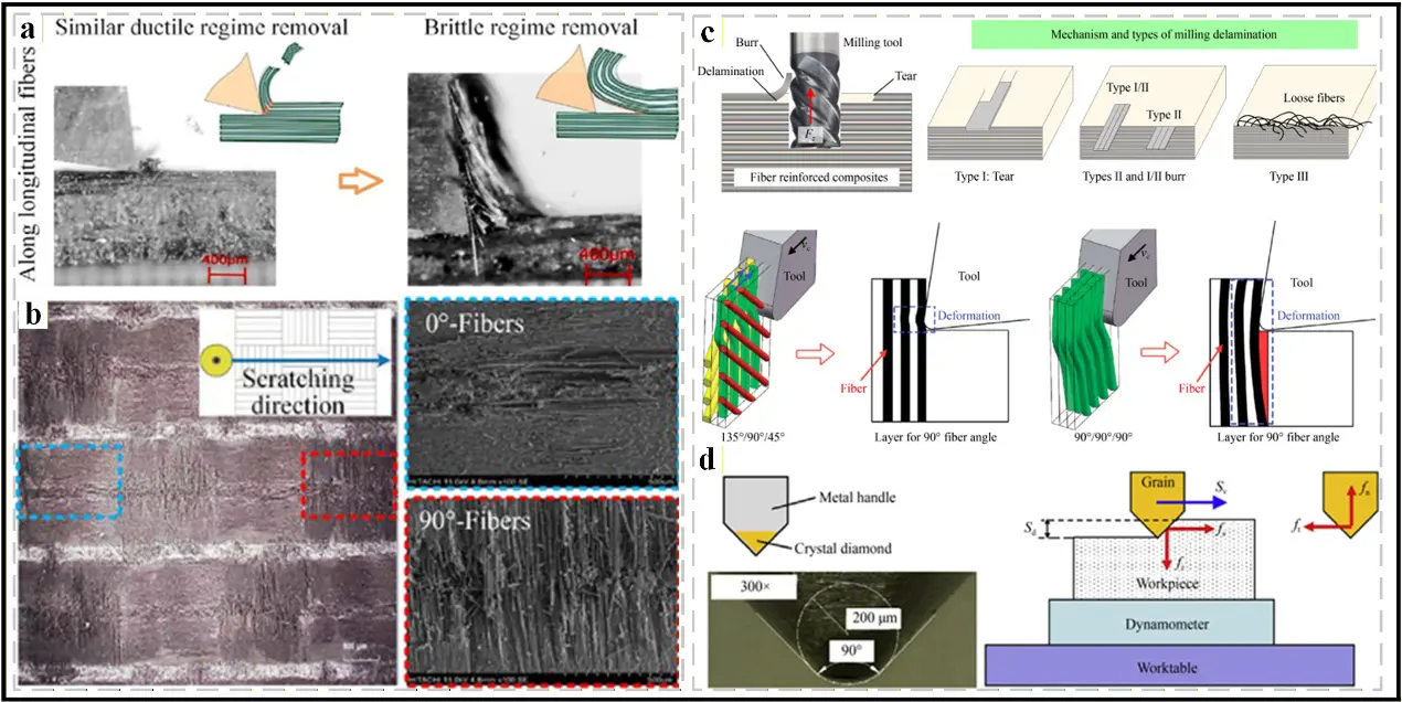
Figure 3. AM process flow. (a) An example of a typical AM process workflow [46]; (b) a geometry-material-machine-process roadmap for AM and Maker Movement [45]; (c) robotics systems in AM for enhanced autonomy [54]; (d) an overview of the integration of ML into AM processes for diverse optimizations [55].
2.2. Additive/Subtractive Hybrid Manufacturing
2.2.1. Working Principle
A/SHM is an innovative, rapid, and direct forming process developed based on AM and SM technologies. Combining the strengths of AM and SM, this technique enables the production of metal components with complex geometries, dense microstructures, high dimensional accuracy, and exceptional surface quality. Consequently, it meets the growing performance demands of advanced fields such as aerospace, defense, and biomedicine [88,89,90]. A/SHM technology can be defined as a process that combines AM techniques with secondary energy sources and tools, which tend to alter mechanical processes, part machining, quality, and functionality synergistically. The principle behind it lies in the integration of product design, software control, AM, and SM technologies. Computer-generated CAD models are segmented into layers of specific thickness by applying them. The three-dimensional data associated with the component is then converted into two- or three-dimensional geometric contour representations. Combining layer geometry information with deposition and machining parameters generates the CNC code for the AM processing path, ultimately forming a three-dimensional solid part. The constructed three-dimensional solid components then undergo measurement and feature extraction. These are then compared with the CAD model to identify areas of deviation. Based on SM, the parts undergo further machining and refinement until they meet the product design specifications. The essence of this technology lies in the CAD software-driven process of three-dimensional stacking and machining. Consequently, a composite machining system must incorporate multi-axis CNC machine tools, AM mechanisms, feed mechanisms, software control systems, and auxiliary systems. Key technologies involved include integrated composite machining models, software and hardware platform development, and composite manufacturing control systems. Figure 5a–d shows the fundamental process flow of this technology. This enables the integration of additive-subtractive hybrid processing on a single machine tool, representing a manufacturing solution that combines the majority of existing SM and AM technologies. In this context, for components with special geometric configurations or composed of special materials that are infeasible via traditional SM, the near-net-shape forming stage can be entrusted to AM, while the subsequent precision machining and surface treatment processes fall under the purview of traditional SM [10,91,92]. Since all machining operations are performed on a single machine tool, this setup not only mitigates the error accumulation arising from workpiece clamping and handling in multi-platform processing scenarios, thereby enhancing manufacturing precision and production efficiency, but also optimizes workshop space utilization and reduces overall manufacturing costs. AM facilitates material deposition and near-net-shape forming, while SM contributes to improved surface integrity, elimination of internal defects, and optimization of stress distribution. The integration of these two technologies enables the realization of final part fabrication with enhanced performance and dimensional accuracy [93,94,95]. The integration of intelligent systems not only elevates the level of technological automation but also significantly optimizes the machining process, mitigating defects induced by human errors [96]. A/SHM technology, through the collaborative innovation of additive forming for near-net-shape creation and subtractive shaping for precision refinement, not only overcomes the precision and efficiency bottlenecks inherent in traditional manufacturing but also inaugurates a new paradigm of design-to-manufacturing integration. As technology continues to evolve and innovate, it will bring forth more transformative changes and opportunities to the manufacturing sector, driving its progression toward higher quality, greater efficiency, and enhanced intelligence [97,98].
2.2.2. Technology Integration and Advantages
A/SHM enables the integrated fabrication of products through the deep fusion of AM and SM processes. This technology exhibits a spectrum of process merits, encompassing high precision, superior performance, enhanced efficiency, material conservation, and weight reduction. Distinguished by its unique process advantages, A/SHM is competent in fabricating complex structural components with high precision and premium quality. It holds promising prospects for extensive research and application in domains such as military, national defense, and aerospace engineering [99,100]. Significant achievements have been made in the research and commercial application of hardware integration of A/SHM technologies based on seven AM techniques. However, the integrated technologies that are currently widely studied and have a relatively high level of commercial application maturity are mainly the hybrid processing integration based on direct energy deposition (DED) and the hybrid processing integration based on powder bed fusion (PBF) [8,101,102]. Due to the much higher deposition rate provided by DED and the possibility of adding materials to existing components, the availability of hybrid processing integration based on DED is significantly more extensive than that of integrated PBF processes. In addition, because materials can be deposited simultaneously along the five axes of the machine, it can build complex geometries without support structures [9,103]. DMG MORI (Bielefeld, Germany) introduced the LASERTEC 65 3D hybrid and LASERTEC 4300 3D hybrid in 2014 and 2016, respectively. The first one is based on the RRLLL motion chain, featuring a tilting worktable and combining the flexibility of laser metal deposition (LMD) with the precision of five-axis milling. The second one includes B-axis tilting motion of the head and the RLLLR motion chain, integrating six-axis LMD and five-axis turning/milling. Both machines are equipped with process monitoring and control devices, such as real-time temperature and melt pool size measurement, enabling automatic laser power adjustment [104,105]. The Japanese company Mazak (Oguchi, Japan) launched the INTEGREX i-200S AM in 2016. This hybrid machine uses the RLLLR motion chain and includes two turning spindles, one milling spindle, and a gantry AM head, integrating multi-LMD with milling/turning. Multi-LMD is a process that uses multiple laser beams to melt metal powder fed through the center of the laser head, ensuring stable metal powder flow even when the laser head is tilted and providing very high precision [104]. The Okuma LASER EX series combines subtractive and additive functions, quenching and coating in one platform. Adjustable parameters of this technology include laser spot size, laser power, powder flow rate, and lateral feed rate. One of the earliest commercial hybrid machines based on PBF composite processing was developed by Matsuura. The Matsuura Lumex selective laser sintering with milling using high-speed spindles with a maximum speed of 45,000 rpm [106]. The equipment was sourced from Matsuura Machinery Corporation, located in Fukui City, Japan. The OPM series can perform SLM and high-speed milling simultaneously. Each layer is milled immediately after construction to achieve high-quality accuracy and precision, even for inaccessible cavities or internal features after the part is completed [107]. Besides hardware integration, software integration has also achieved significant results. Cloud manufacturing can be utilized to overcome the challenges associated with traditional systems to achieve on-demand and reliable manufacturing capabilities. To achieve highly automated and dynamic control of A/SHM technology, Industry 4.0 focuses on the connection of hybrid manufacturing technology with the cyber/digital domain. In this regard, a cloud-based framework was developed for the online diagnostic architecture, where machine tools and sensor systems are connected to the cloud to coordinate and control cyber-physical systems (CPS). In digital manufacturing, automation is integrated into knowledge-evolving devices to achieve intelligent transformation, which can make decisions in a machine-to-machine communication environment. Through online identification and feedback, autonomous path planning and in-situ parameter adjustment can be achieved. Additionally, by using sensors and the Internet of Things to connect physical resources (machines, tools, workpieces) with complex CPS, the risk of damaging workpieces, tools, and the machines themselves can be reduced, thereby enhancing productivity [4,108]. As shown in Figure 5e, TO algorithms for A/SHM are another active area of research in the software integration [109]. With the improvement of hardware integration and the development of software intelligence, this technology will become a key supporting technology in high-end equipment manufacturing, aerospace, biomedicine, and other fields, promoting the deep transformation of the manufacturing industry towards personalization, efficiency, and greenness [110,111]. Table 1. presents a summary and comparison of manufacturing technologies. A/SHM has demonstrated outstanding advantages over AM and SM.
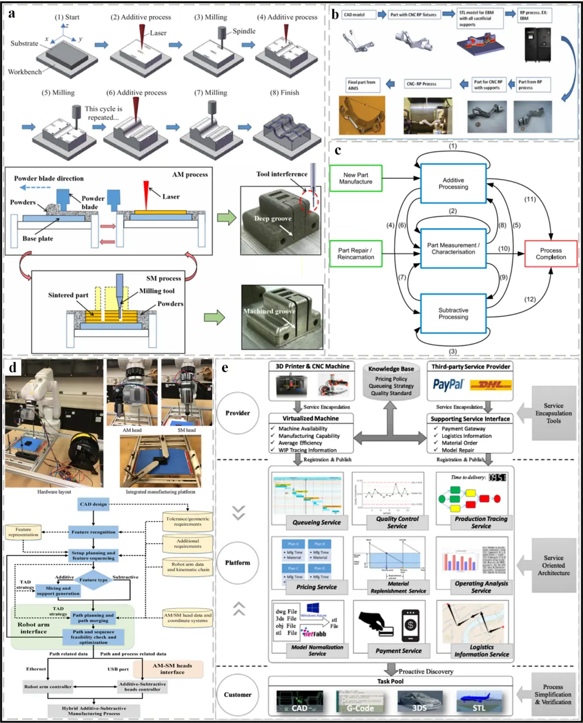
Figure 5. The principle of the A/SHM process. (a) Schematic description of the A/SHM process [89,94]; (b) AIMS: Integrated AM and CNC-RP integrated flow illustration [90]; (c) process interactions within A/SHM process [91]; (d) hardware layout of A/SHM process and Schematic view of the software and control flow for the A/SHM process [88]; (e) collaborative platform for the cloud-based A/SHM resources [4].
Table 1. Summary and Comparison of Manufacturing Technologies.
|
Technical Classification |
Technical Characteristics |
Applicable Scenarios |
Core Advantages |
Major Defects |
|---|---|---|---|---|
|
AM |
Complex, irregularly shaped parts are created by depositing materials layer by layer. |
Customization, complex and irregularly shaped parts, and small-batch production. |
High material utilization, suitable for small batches and custom orders |
High surface roughness, high porosity, RS, and cracking are commonly observed |
|
SM |
Removes excess material with high precision and a smooth finish |
High-volume standard parts, high-precision standard parts |
High precision, High surface quality, mature technology, and high cost-effectiveness |
Complex internal cavities are difficult to machine, resulting in significant material waste |
|
A/SHM |
AM and SM: Integrated Processing |
Repair of high-end, precision, and complex components |
Balancing complexity and precision while reducing setup operations |
The equipment is costly, and the process and operational requirements are onerous. |
3. The Mechanism of Residual Stress Generation and Influencing Factors
3.1. Mechanism of Residual Stress Generation
Table 2 shows the mechanism of pressure generation. Thermal residual stress (TRS) refers to the internal stress generated when an object undergoes temperature changes due to its inability to deform freely. The fundamental cause is the combination of temperature changes and constraints. Constraints can be classified into three types: external deformation, mutual deformation, and internal component deformation [15,112]. TRS is divided into thermal elastic stress and thermal plastic stress [113,114]. In composite materials, TRS originates from three levels: microscopically, the difference in thermal expansion coefficients (CTE) between fibers and matrix; macroscopically, the CTE difference between anisotropic layers leading to the deformation of laminated plates; and overall, the cooling rate in the thickness direction and temperature gradient generating stress distribution [15,115,116]. TRS can cause fiber waviness, warping, and transverse cracks, thereby reducing mechanical properties, and its relationships with compressive, shear, and other properties are not yet clear [117,118]. Quantitative analysis should be combined with heat conduction and equilibrium equations, and management can be achieved through material selection, structural optimization, and process control [119,120]. Mechanical stress is the internal resistance generated when an object is deformed due to external forces, boundary constraints, or temperature changes. It mainly results from external constraints or internal structural hindrances, such as restricted casting shrinkage and limited welding cooling [121,122,123,124]. It is classified into types such as tension, compression, shear, and torsion, and its magnitude depends on external forces, size and shape, material properties, and process parameters [125,126]. The stress-strain curve describes the deformation characteristics; it is classified into static stress and dynamic stress according to the duration of action [127,128]. Understanding mechanical stress is helpful for optimizing structures, improving processes, and conducting failure analysis [129,130]. Phase transformation stress is the internal stress generated during a solid-state phase transformation due to volume differences, inconsistent phase transformation times, and shear effects [131,132]. The core mechanism is volume deformation constraint, asynchronous phase transformation, and shear phase transformation [133,134]. The magnitude of stress depends on material properties, process parameters, phase transformation plasticity, stress relaxation, and the distribution of phase transformation products and grain size [135,136]. Understanding phase transformation stress is helpful for predicting and controlling deformation cracking and optimizing material properties [137,138].
Table 2. Stress generation mechanism.
|
Stress Type |
Mechanism of Generation |
Key Influencing Factors |
|---|---|---|
|
TRS |
Constrained, non-uniform thermal deformation |
Temperature gradient, CTE, constraint conditions, and cooling rate. |
|
Mechanical stress |
Resistance to deformation under external loads |
External load, member geometry, and material stiffness. |
|
Phase transformation stress |
Phase transition volume change |
Compare tolerance, cooling rate, and phase transformation type. |
3.2. Analysis of Influencing Factors
In A/SHM processes, the generation of RS is influenced by a combination of factors, including material properties, process parameters, and environmental conditions [21,139]. This section will provide a detailed examination of these three primary factors.
3.2.1. Material Properties
The thermophysical properties, mechanical properties, crystal lattice structure, and chemical composition of metallic materials decisively influence the formation and distribution of RS [140,141]. Pokharel et al. [142] found that the difference in CTE between austenite and ferrite causes significant RS within the component and triggers plastic deformation in ferrite. Deformation and orientation mismatches at grain boundaries intensify stress concentrations, which may lead to failure, as shown in Figure 6a. Bouafia et al. [143] conducted a FE analysis on the TRS of SiC particle-reinforced aluminum matrix composites. As shown in Figure 6b,c, the volume fraction and shape of SiC particles have a significant impact on the RS: an increase in the volume fraction raises the RS in the matrix but reduces the stress within the particles; uneven particle distribution is prone to causing stress concentration and cracks. Katie et al. [16] conducted an in-depth analysis of the RS generated in five complex lattice structures during A/SHM processes. As shown in Figure 6d, the average RS in the primitive lattice structure was approximately 350 MPa, with a peak RS of around 800 MPa observed along the outer edges of the structure. Compared to the primitive lattice structure, the isosteres distribution across the geometric surface of the I-WP lattice structure is more uniform. The lowest RS occurs at the bottom surface in contact with the build plate, ranging from approximately 200 to 300 MPa. The isosteres distribution of the diamond lattice structure closely resembles that of the I-WP lattice structure, but exhibits a more uniform pattern. The gyroid lattice structure exhibits equivalent stresses ranging from 250 to 750 MPa, with contour plots resembling those of the diamond lattice structure. The lilioid lattice structure displays a broader equivalent stress distribution, with the lowest equivalent stresses observed at the center of the lattice and at the bottom surface layer in contact with the build plate. Of the five lattice structures, the primitive lattice structure exhibits the lowest average equivalent stress, at 350 MPa. The maximum RS values for all lattice structures fall within the range of 700–750 MPa. Although the equivalent stress distribution of the primitive lattice structure is in the lower range, its shape is comparable to that of the diamond and gyroid lattice structures. Compared to other structures, the I-WP and lidinoid lattice geometries exhibit broader distributions and wider spans. Mael et al. [144] conducted an experimental study on the wet-mechanical behavior of asymmetric bio-composites. As shown in Figure 6e, during the moisture diffusion process, the inner and outer layers of the laminate generate complex stress distributions due to restricted expansion: in the initial stage, the outer layer is subjected to compressive stress due to constrained expansion; as moisture diffuses to equilibrium, the stress state reverses and a specific tensile/compressive stress distribution is formed due to the curvature of the laminate. Zhang et al. [145] investigated the high-speed compressive behavior of three-dimensional braided composites via FE. As shown in Figure 6f, under impact loading, stress concentrations are distributed along the undulating warp yarns; structural failure is predominantly governed by interfacial debonding and shear failure. Under loading in different directions, fiber bundle buckling, matrix damage, and the Poisson effect collectively dictate the final failure mode and mechanical strength. He et al. [146] investigated the effect of thermal RS on the mechanical properties of fibre-reinforced polymer (FRP). Figure 6g shows that the effect of thermal RS on the longitudinal strength of FRP is negligible. In transverse compression, TRS exerts an adverse effect: it superimposes with the applied load, inducing the formation of shear bands with extensive matrix plasticity and interfacial debonding. Consequently, the material fails earlier compared to the scenario without TRS. Through the synergistic optimization of materials, processes, and post-treatment, the performance and reliability of metal components manufactured via A/SHM can be significantly enhanced, thus advancing their application in the fields of aerospace and energy [147,148].
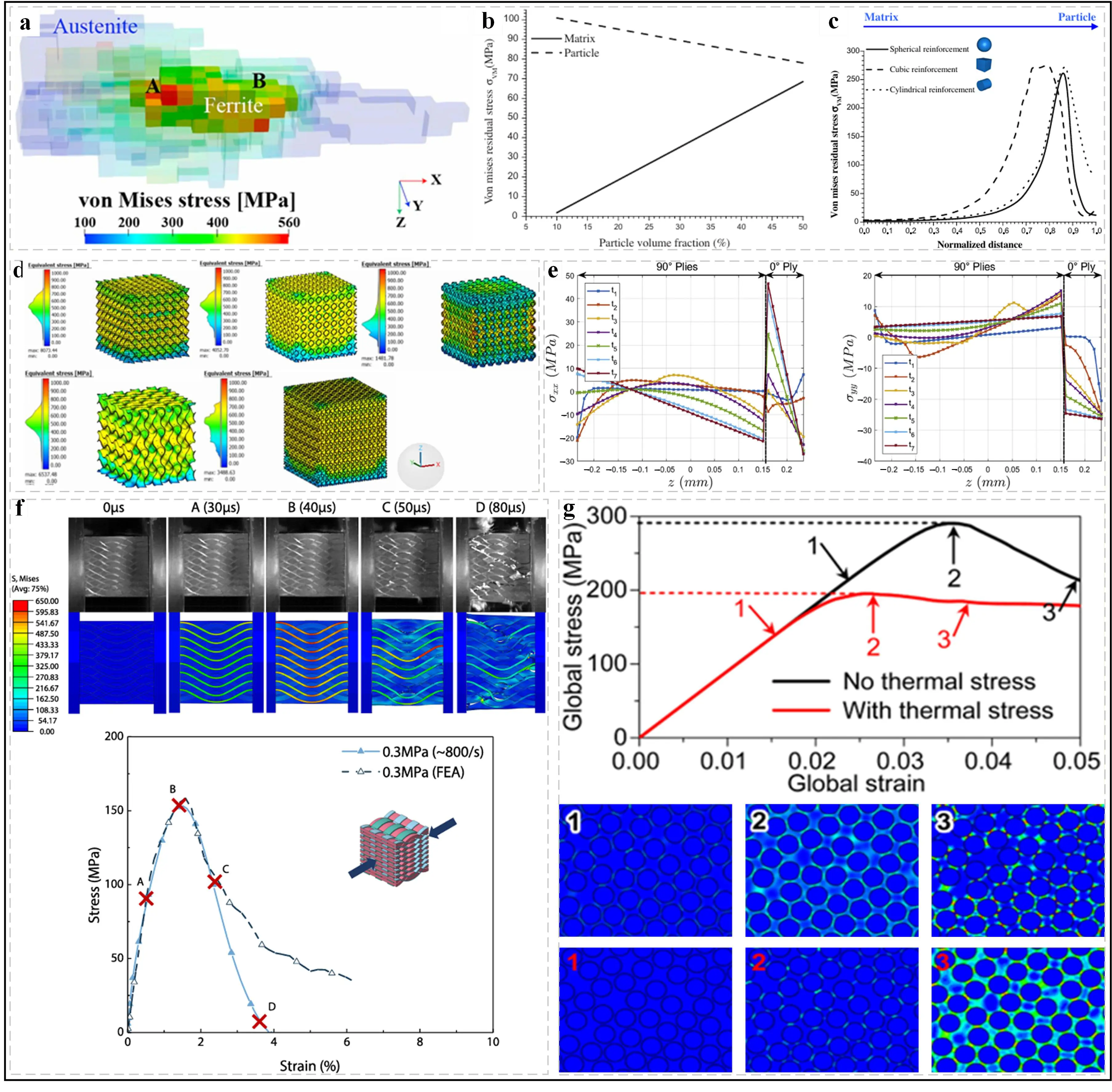
Figure 6. Influence of Materials. The predicted results of the micro-mechanical field: (a) von Mises stress [142]; the equivalent and normal RS vary with the change in (b) particle volume fraction and (c) in particle geometry [143]; (d) equivalent Stress distributions for whole models of all 5 lattice structures [16]; (e) distribution of global stress components σₓₓ and σᵧᵧ [144]; (f) deformation history of the specimen at several representative points [145]; (g) comparison of the stress-strain curves [146].
3.2.2. Process Parameters
RS generated during A/SHM can have a significant impact on the mechanical properties and performance of components, potentially leading to deformation, warping, cracking, and other forms of degradation. Process parameters are among the key factors influencing the formation and distribution of RS, making it crucial to investigate their effects [149,150]. This section examines the mechanisms through which RS are influenced by factors such as energy density and scanning strategy.
Different process parameters exert varying effects on RS in A/SHM processes. Lu et al. [7] investigated the influence of deposition height and laser energy density. As shown in Figure 7a, with the increase of printing height, the intrinsic heat treatment effect and the maximum temperature gradient (MTG) decrease, and the overall RS is reduced, but stress concentration still occurs at the corners of the component. Increasing the energy density helps to reduce the RS, but at the same time, it will aggravate the warpage of the part due to the increase in the temperature gradient. Li et al. [17] investigated the effects of milling and electrochemical corrosion on the RS of the surface of 316L stainless steel fabricated by Laser additive manufacturing (LAM). As shown in Figure 7b, the stress at the bottom of the thin wall is the smallest, and the tensile stress at the top corner is the largest. After electrolytic corrosion, the stress distribution shows asymmetry, with tensile stress at the edge and compressive stress at the center, which is related to the tip effect during the corrosion process and the non-uniformity of the process. Zhang et al. [151] conducted a comprehensive investigation into the impact of heat input on the deformation and RS of aluminum alloy components produced using electron beam melting, employing a three-dimensional transient thermo-mechanical coupled model. Assuming that the heat input used in the preceding cross-section is Q, Figure 7c shows that stresses concentrate within the deposited layer, with residual tensile stress (RTS) increasing as the level of heat input rises. This is because higher heat input leads to greater temperature gradients, thereby amplifying RS. Therefore, to control RS, heat input can be appropriately reduced. Scanning strategies also significantly influence RS. Parry et al. [18] compared the unidirectional and alternating laser scanning strategies. As shown in Figure 7d, the alternating scanning strategy reduces the temperature gradient because the next scanning vector starts from the already completed high-temperature zone of the previous pass, thereby reducing the plastic strain and RS at the end of the scan. Chen et al. [152] investigated the influence of the inter-island overlap rate in the isolated island scanning strategy. As shown in Figure 7f, as the overlap rate increased from 5% to 25%, the high-stress area in the first scanned island (Island 1) decreased, but that in the subsequent island (Island 2) increased. When the overlap rate increased from 50% to 100%, the RS showed an overall upward trend, as the temperature gradient effect caused by the increased scanning length exceeded the stress relief effect of re-scanning. Zhang et al. [153] systematically analyzed three scanning strategies (opposite S scanning, parallel S 90° rotation scanning, parallel S no rotation scanning). As shown in Figure 7e, the parallel S scan without rotation produced the highest maximum principal stress (1504 MPa). The parallel S 90° rotation scan resulted in a lower and more uniform stress distribution. In contrast, the opposite S scan had a higher RS than the parallel S 90° rotation scan due to its higher peak temperature and larger temperature gradient. Popineau et al. [6] investigated the development and evolution of moisture stress in asymmetric bio-composites made of flax/Polypropylene + Maleic Anhydride grafted Polypropylene (PP + MAPP) when exposed to ‘saturated’ moisture cycles. Figure 7g shows that cyclic tensile stresses affect the transverse direction of the PP + MAPP material when it is continuously exposed to low relative humidity. These sustained internal stresses induce progressive damage to the material, leading to the relaxation of moisture-induced stresses throughout the cycle. When samples were exposed to cycles with higher relative humidity, changes in moisture content, reduced tensile properties, permanent out-of-plane expansion and curvature were found to be more pronounced. When exposed to humid environments, flax fibres begin to swell, whereas the PP + MAPP matrix remains relatively insensitive to the presence of water. Due to the anisotropic nature of flax fibres, fibre swelling leads to unidirectional strand expansion, resulting in irreversible damage. Larger moisture content gradients imply greater relaxation of plastic matrix deformation in the interface region.
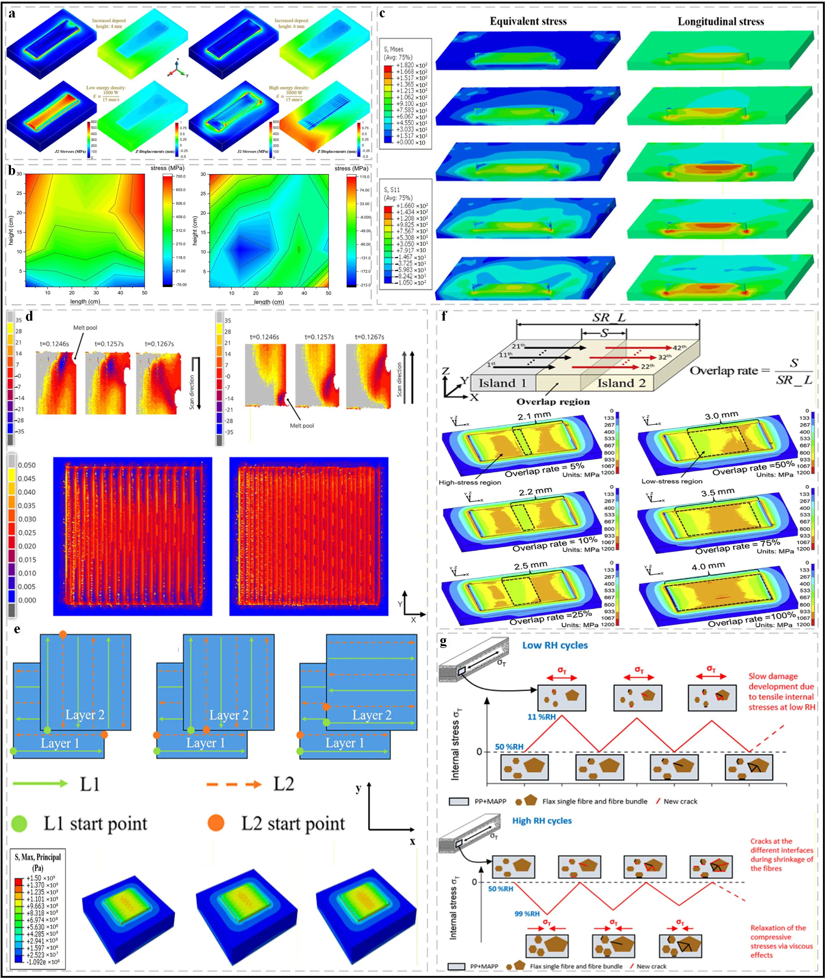
Figure 7. Process parameter influence. (a) Contour-fills of residual von Mises stresses and the vertical displacements [7]; (b) RS distribution after electrolytic corrosion [17]; (c) the effect of heat input on stress distribution [151]; (d) stress and strain field profiles of different strategies [18]; (e) the final maximum principal stress for the different scanning strategies [153]; (f) schematic diagram of island strategy and the equivalent stress distribution [152]; (g) internal stress evolution during successive low and high RH exposure [6].
4. Measurement and Characterization of Residual Stress in Additive/Subtractive Hybrid Manufacturing
4.1. Methods of Measuring Residual Stress
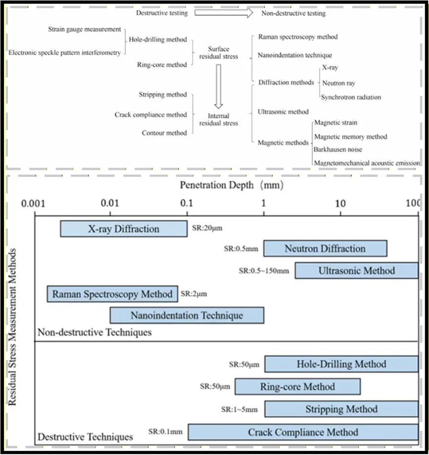
In recent years, a variety of methods have been developed to measure RS in different types of components. Figure 8 shows that the current techniques can be categorized into two types based on their principles: destructive and non-destructive testing (NDT). Destructive testing, also known as mechanical release methods, infers original stresses from displacements generated by the complete or partial elimination of stresses through material removal. This approach involves measuring the deformations caused by the release of RS during the extraction of material from specimens. The primary destructive methods for measuring RS in structural components are drilling, ring core extraction, and contouring. NDT methods, also known as physical testing methods, primarily measure RS based on the physical properties of the material. X-ray diffraction (XRD), neutron diffraction (ND), ultrasonic methods, and magnetic methods are common NDT techniques [19,154,155]. This chapter will detail the principles and applications of XRD, ND, mechanical release methods, and novel detection techniques.
XRD is a non-destructive technique used to measure RS on material surfaces. When metals are subjected to RS, the resulting elastic strain causes atomic planes within the metal crystal structure to alter their interplanar spacing. XRD can directly measure this interplanar atomic spacing, thereby determining the total stress on the metal. This method is suitable for crystalline materials with relatively fine grains and produces diffraction in any direction from the sample surface [155,156], as shown in Figure 9a. Felix et al. [157] utilized in-situ XRD to observe the strain evolution within the heat-affected zone of SLM and divided it into four characteristic regions, revealing the compression and tension strain mechanisms caused by the TGM at different stages, as shown in Figure 9b. The principle of ND is similar to that of XRD. Both rely on elastic deformations within polycrystalline materials. These deformations alter the spacing between crystal lattice planes from their stress-free state. Compared to XRD techniques, ND has the advantage of greater penetration depth. This is particularly useful for alloys with high average atomic numbers, for which XRD penetration rapidly diminishes [158,159]. Lee et al. [160] developed a predictive model for RS in A/SHM and validated it using ND. As shown in Figure 9c, the elastic strain distribution predicted by the model is basically consistent with the measured values. However, in some directions, due to the model not considering the additional stress caused by phase transformation, there are differences between the prediction and the measurement.
The drilling method, currently the most widely applied RS measurement technique, offers advantages such as high precision, low equipment cost, and semi-destructive testing. Typically, after drilling a small hole containing RS on the workpiece surface, the stress near the hole is released and redistributed. Three sets of strain gauges positioned on the same circumference can then be used to measure the corresponding radial strain data [19,161,162]. As shown in Figure 9d. Li et al. [163] developed a transient three-dimensional model to investigate the TRS evolution and RS distribution of circular thin-walled parts produced by WAAM. The RS generated in the substrate and deposited layers was measured via the drilling method, validating the model’s effectiveness. As shown in Figure 9e, owing to the unique thermal properties of the circular component, stress relaxation occurs in the layers near the start and end points of the arc, and the RS distribution characteristics vary across different positions of the component. The RS distribution of the part obtained from the simulation results facilitates a deeper understanding of the complex thermomechanical mechanisms involved in WAAM. The contour method, an emerging technique for RS measurement, has undergone over two decades of development and is now finding application in the field of welding RS measurement. Its working principle is as follows: a workpiece containing RS is cut along the region where RS needs to be measured. Due to stress release and redistribution, the profile of the cut surface undergoes deformation. An external reverse stress is then applied to the interface to restore the deformed cut surface to its pre-cut planar state. Based on the Bückner superposition principle, the applied external reverse stress corresponds to the RS [155,164,165], as shown in Figure 9f.
Nanoindentation is a technique that involves creating submicron-scale indentations on a material surface while recording the applied load and indentation depth, enabling the determination of material properties. It is widely employed for RS measurement in diverse materials, including aluminum alloys, metallic glasses, and polycrystalline materials [166,167]. Overall, nanoindentation technology has the advantages of NDT and high efficiency, and the related computational models are relatively well-developed. However, the accuracy and application scope of the models still need to be further determined. The combination of FE simulation has greatly promoted the development of nanoindentation technology, but due to the deviation of the boundary conditions in FE simulation from the actual situation, some methods still need to be improved [168,169]. Magnetic memory testing is an emerging NDT technique. When a magnetized metal workpiece is subjected to external loading, irreversible changes in magnetization intensity within stress concentration regions and material discontinuities in the metal component can induce local magnetic signal anomalies in these stress-concentrated areas. These anomalies persist as a residual leakage magnetic field even after the load is removed. Stress concentration regions in the workpiece can be inferred from variations in the measured magnetic signal curves and the corresponding gradient values of the magnetic signals [170,171].
In A/SHM, the distribution of RS arises from stress evolution. Measuring stress evolution in A/SHM represents a significant challenge for current research techniques [162]. Most studies on A/SHM online monitoring have focused on directly measurable deformations, employing techniques such as laser displacement sensors, differential variable reluctance transducers, and coherent gradient sensing [140,172]. Zeng et al. [173] designed an optical path that enabled a three-dimensional digital image correlation (3D-DIC) system to measure the displacement field at the bottom of the substrate, while an infrared thermography camera was used to capture the temperature field. The acquired displacement and temperature fields were then input as boundary conditions into a FE model to compute the stress evolution process within the substrate. Bartlett et al. [174] developed a 3D-DIC-based non-destructive framework for measuring stress evolution in SLM. 3D-DIC was utilized to capture in-situ surface deformations of parts during SLM, as shown in Figure 9g. Subsequently, the two-dimensional elastic Kirchhoff plate equation was applied to convert the experimental deformation data into estimates of in-plane RS. In recent years, A/SHM has developed a closed-loop RS control system comprising multi-source sensing, feature extraction, ML, and coupled FE modeling. Lee et al. [160] validated the residual strain/stress prediction method for WAAM hybrid manufacturing using ND, while Heigel et al. [175] systematically investigated through experiments the mechanism by which RS in AM affects subsequent machining deformation. Related studies have employed SVR algorithms to build RS prediction models for the Inconel 718 superalloy, utilized deep learning for real-time monitoring of RS in hybrid manufacturing, and applied physics-guided ML surrogate models to verify TRS field predictions, significantly improving prediction efficiency and optimizing forming stress levels. However, data-driven prediction technologies still face significant limitations. Due to differences in experimental conditions across research groups, existing datasets vary widely in quality. Moreover, there is a lack of unified calibration standards for diverse inspection methods such as XRD and ND. Most current intelligent models are tailored only to specific equipment and materials, resulting in substantially increased prediction errors when transferred across different operating conditions. A universally applicable prediction framework remains to be further developed [160,175,176,177]. Table 3 shows the comparison of detection methods, and each of the six testing methods has its own advantages and disadvantages. Suitable detection methods can be selected according to different situations.
Table 3. Comparison of detection methods.
|
Method |
Advantages |
Disadvantages |
Spatial Resolution |
Detection Depth |
Applicable Operating Conditions |
|---|---|---|---|---|---|
|
XRD |
ND testing, capable of diffraction in any direction on the sample surface. |
Low penetration depth, limited to surface stress. |
Micron to millimeter level |
Surface layer (tens of micrometers) |
Surface RS measurement |
|
ND |
High penetration depth, ND testing |
The equipment is expensive and requires a neutron source; spatial resolution is relatively low. |
Millimeter-level |
Centimeter-level |
Measurement of large-scale or deep RS |
|
Drilling |
High precision; low equipment cost; mature technology |
Strain gauges need to be attached. |
Millimeter-level |
Typically 1 to 2 times the aperture size |
Measurement of RS on Metal Component Surfaces |
|
Contour Method |
Measure two-dimensional full-field stress distribution, |
Damages the specimen, requires specialized equipment. |
Submillimeter-level |
The entire cross-section |
Two-dimensional distribution characterization of RS in welded components and large-sized parts |
|
Nanoindentation |
High efficiency; relatively mature computational models. |
Model accuracy and application scope still need further clarification |
Submicron-level |
from hundreds of nanometers to several micrometers |
Micro-area, thin film, coating, and localized RS measurement |
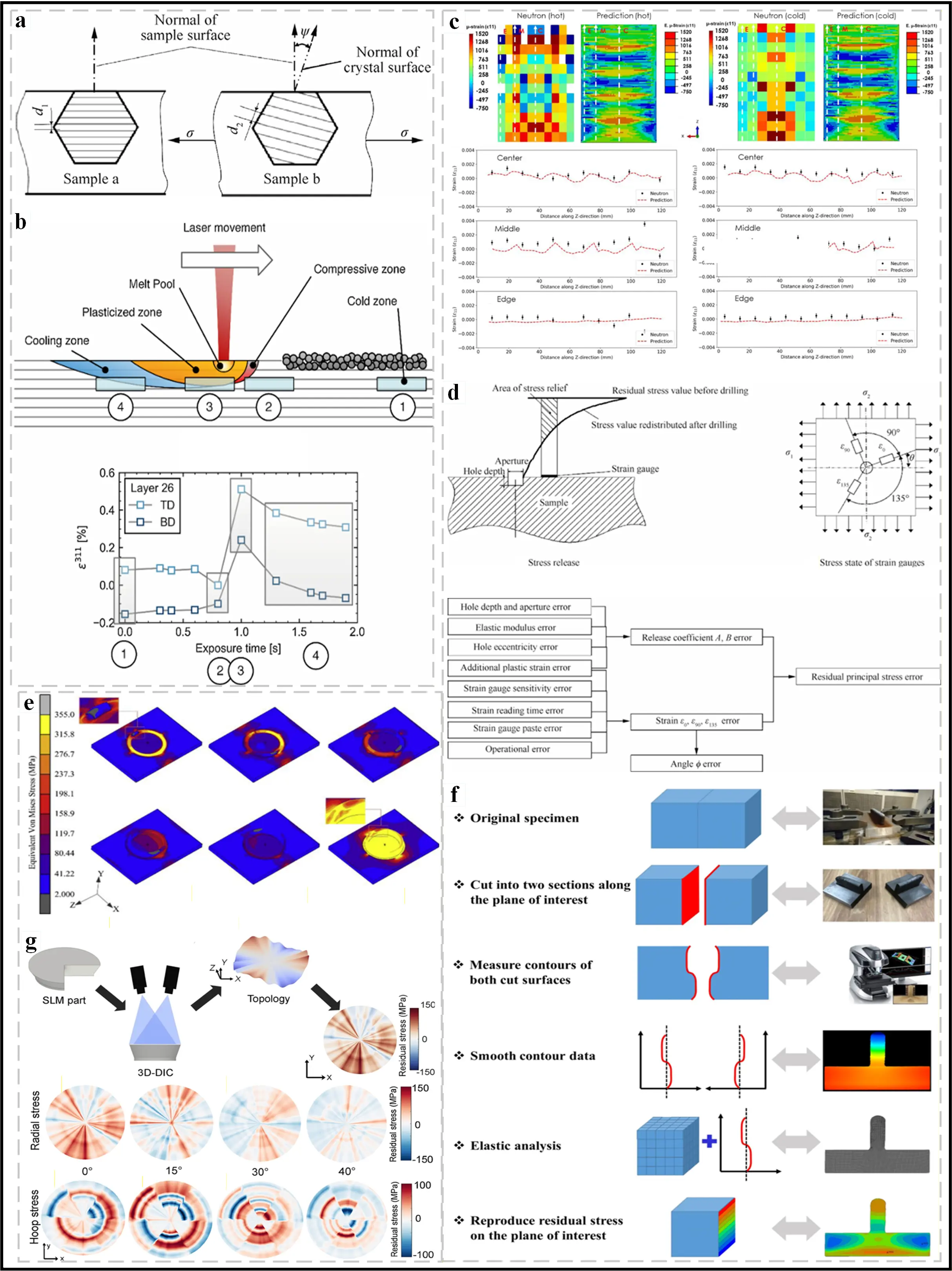
Figure 9. Method for measuring RS. (a) schematic diagram of spacing between crystal planes varying with stress [19]; (b) model of the heat affected zone [157]; (c) Residual strain distribution [160]; (d) Schematic diagram of strain gauge hole-drilling method and error chain in hole-drilling method [19]; (e) equivalent Von Mises stress evolutions in the deposition process [163]; (f) schematic representation of RS measured [178]; (g) In-situ monitoring of stress evolution process in SLM [174].
4.2. Characterization and Analysis of Residual Stress
Effective control of RS in A/SHM requires precise detection and efficient analysis for accurate prediction. Integrating high-precision characterization with in-depth analysis enables an understanding of the distribution patterns and levels of RS, which allows for their effective prediction, control, and optimization in A/SHM. This improves the mechanical properties and dimensional accuracy of the final product [179,180]. This chapter systematically summarizes the distribution patterns and level analysis of RS.
4.2.1. Stress Distribution Patterns
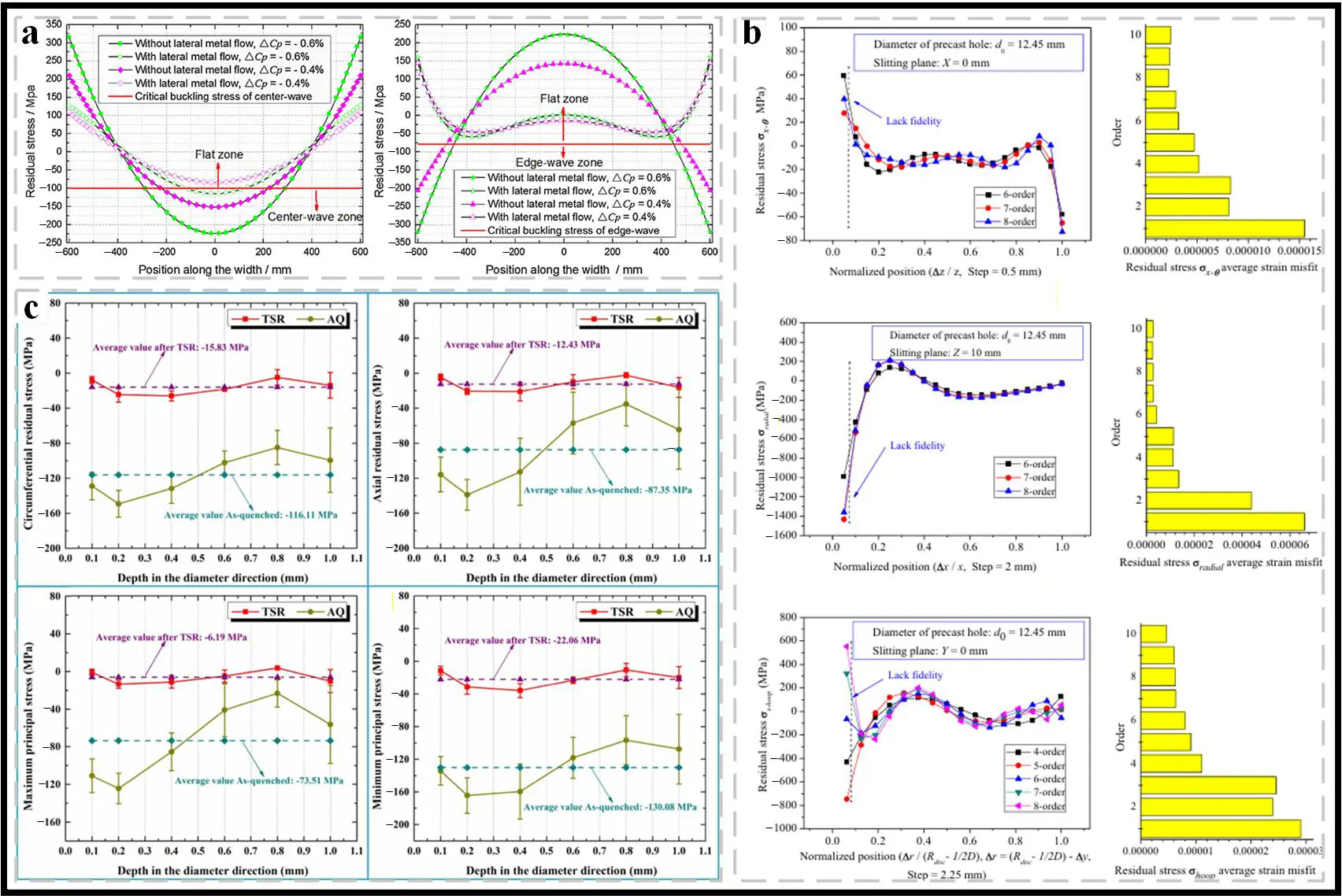
In A/SHM, comprehending the distribution characteristics of RS is of paramount importance, as it directly governs the performance, quality, reliability, and production efficiency of components [181,182,183]. Zhao et al. [33] analyzed the influence of the lateral flow of metal in hot-rolled strip steel. As shown in Figure 10a, introducing lateral flow can transform the RS distribution from a mode that causes buckling to a flat or W-wave mode, significantly reducing the buckling risk factor and enhancing the flatness and safety margin of the strip. Huang et al. [184] investigated the influence of abrasive belt wear on the distribution of grinding RS. With the increase of wear, the tangential RS changes from residual compressive stress (RCS) to RTS, and the uniformity of its distribution decreases; while the axial RS remains RCS and its mean value increases with the increase of wear. Hou et al. [185] investigated the RS after the trapezoidal internal thread extrusion processing. As shown in Figure 10b, the RS in the thickness direction of the component is a uniform compressive stress, while there is a relatively high local compressive stress in both the radial and circumferential directions near the hole opening. Song et al. [186] investigated the impact of thermal stress relief (TSR) and quenching processes on RS distribution in 2219 aluminum alloy. Figure 10c shows that RS along the thickness direction first decreased, then increased, and finally decreased again, peaking at 0.2 or 0.4 mm and reaching a minimum at 0.8 mm. Due to severe temperature non-uniformity inducing large thermal gradients, the as-quenched (AQ) specimen exhibited large, highly fluctuating RS. Compared to the AQ state, the TSR-treated specimen showed an 86.37% reduction in circumferential RS (from −116.11 MPa to −15.83 MPa), an 85.77% reduction in axial RS (from −87.35 MPa to −12.43 MPa), a 91.58% reduction in maximum principal stress (from −73.51 MPa to −6.19 MPa), and an 83.04% reduction in minimum principal stress (from −130.08 MPa to −22.06 MPa). These results indicate that TSR more effectively mitigates maximum principal stress, leading to a more uniform RS field. Idarraga et al. [187] analyzed the stress distribution in the oxide layer through Raman peak shifts and found that the stress decreased from the metal/oxide interface to the outer surface, and there was stress relaxation or concentration near the crack and in the tetragonal zirconia region. Sun et al. [188] investigated the dynamic propagation of stress waves and the distribution of RS after laser shock peening (LSP). The superposition of the reflected tensile stress wave and the unloading wave generates RTS at the center of the bar, and an increase in the spot size enhances this effect.
Unlike single AM or SM, interlayer milling is a machining process inserted between adjacent deposited layers in A/SHM, distinct from final finishing. Its core lies in actively intervening in RS evolution through mechanical removal coupled with thermal effects, forming a deposition-milling-deposition cyclic control mode. This process alters the stress state via three key mechanisms [189,190,191]. Xu et al. [189] proposed an innovative hybrid manufacturing approach combining LAM, subtractive milling, and ultrasonic rolling. Results showed that RS in the AM sample originated from rapid heating and cooling during AM, and subtractive milling introduced compressive stresses on the surface of deposited layers, further increasing RS in the A/SHM sample. Interlayer ultrasonic rolling induced compressive stresses penetrating deeper than 0.4 mm, resulting in the highest average RS (−539 MPa) for the ultrasonic rolling sample, compared to −362 MPa for the AM sample and −416 MPa for the A/SHM sample. Subsequent additive processes did not eliminate the effects of the interlayer hybrid treatment. At a depth of −1 mm, A/SHM samples exhibited higher and more uniform stress distributions, indicating that interlayer milling and rolling improved internal stress conditions. Karunakaran et al. [190] achieved hybrid amplitude modulation of Ti-6Al-4V by integrating DED with interlayer milling. Studies revealed that DED generates tensile stresses near the surface, leading to part weakening and deformation, whereas milling titanium alloys introduces compressive stresses, thereby improving surface integrity. Interlayer milling reduced RS by 33%. Compared to the original printed sample, interlayer milling decreased RS along the milling feed direction by 32% and perpendicular direction by 41%. Necati et al. [191] investigated stress distribution patterns on the machined surface and subsurface during micro-milling of LPBF-fabricated Ti-6Al-4V alloy. The study found that increased cutting passes led to greater material strain hardening, thereby increasing maximum compressive RS beneath the machined surface, intensifying plastic deformation and mechanical loading. In A/SHM, alternating thermal loads from deposition and mechanical loads from milling create unique thermo-mechanical coupling effects that modify component stress evolution across three dimensions: plastic deformation, stress redistribution, and thermal boundary conditions [175,192]. Liu et al. [192] conducted comparative experiments on IN718 superalloy using cold milling at room temperature versus immediate high-temperature milling after deposition. Under high-temperature milling conditions, thermal softening reduced material yield strength, increasing the depth of plastic deformation from 0.12 mm at room temperature to 0.27 mm, transforming the original surface tensile RS of 380 MPa into compressive stresses ranging from −220 to −310 MPa. Heigel et al. [175] fabricated stainless steel cylindrical parts using PBF, pre-milling the outer circumference before secondary deposition. Milling thinned the side walls, improving heat dissipation efficiency by 32%, reducing the maximum temperature gradient during secondary deposition by 21%, and decreasing newly generated tensile RS by 33.6% compared to pure additive samples without pre-milling. Intermittent cooling due to process interruptions is a distinctive factor that differentiates hybrid manufacturing from continuous additive fabrication, categorized as short-term interlayer cooling and long-term full-process cooling based on dwell time [193,194]. Zhou et al. [193] performed pulsed laser-based additive-subtractive experiments, introducing 30-s intermittent cooling after each layer deposition. The average temperature gradient of the specimen decreased by 16.7% compared to continuous processing, and maximum RS dropped from 458 MPa to 372 MPa. However, when intermittent cooling was extended to 90 s, significant base material cooling caused reversed expansion of interlayer temperature differences, causing RS to rebound to 429 MPa. Lisiecki et al. [194] employed intermittent low-temperature nitrogen cooling assisted laser A/SHM: under intermittent low-temperature cooling conditions, the surface stress of the WC-Ni composite coating changed from a tensile stress of 295 MPa in conventional processing to a compressive stress of −187 MPa, and the peak RS across the entire component decreased by 41%, verifying that the intermittent cooling strategy can effectively optimize the stress state in a targeted manner.
4.2.2. Stress Level Assessment
In A/SHM, the assessment of stress levels is of critical importance, as it ensures component quality and performance, prevents processing defects, and guides process optimization [195,196].
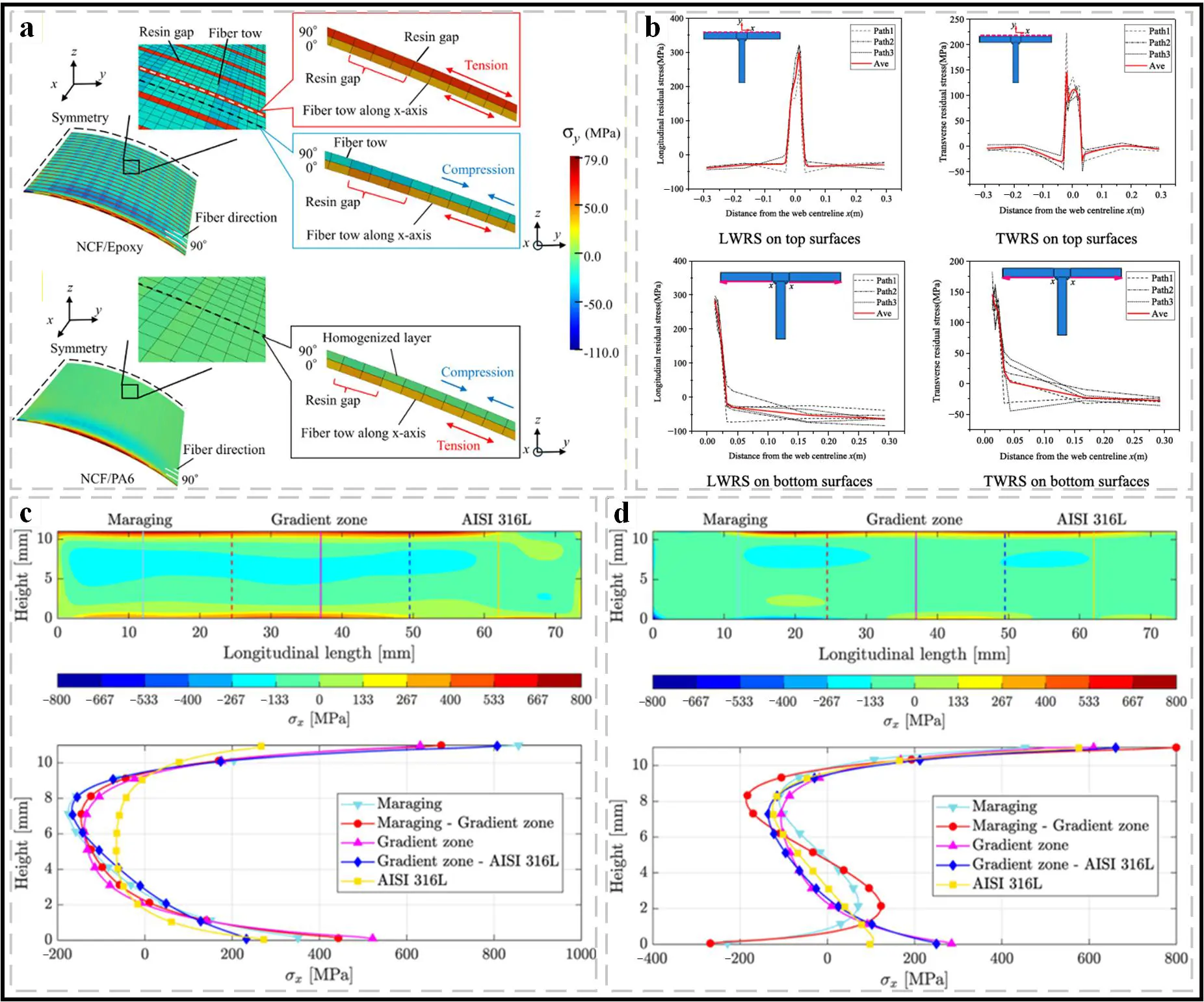
Hemmesi et al. [124] investigated the evolution of welding RS under multiaxial loading using a FE model. When the applied tensile stress was below the material’s yield strength (450 MPa), the RS remained stable; once the yield strength was reached, the RCS at the weld toe and heat-affected zone was almost eliminated. Yuan et al. [197] proposed a multiscale model to predict RS in composites during curing. Fibers primarily bear RCS, while resin carries RTS. However, due to macroscopic mechanical strain, resin exhibits compressive micro-strain in the z-direction. The interface layer sustains RTS in the x-direction and compressive stress in the other two principal directions. Koo et al. [198] introduced viscoelastic dual-scale modeling to predict process-induced RS in non-crimp fabric (NCF) composites reinforced with epoxy and PA6 resins. Figure 11a shows stress levels in the y-direction: a significant stress concentration is observed in NCF/epoxy composites, particularly in the resin gaps of the 90° layer, due to fiber-bundle constraints that generate tensile stress. In contrast, fiber bundles in the 90° layer experience compressive stress from resin gap constraints and 0° layer shrinkage. In the 0° layer, consistent shrinkage between fiber bundles and matrix resin induces bending. These findings indicate that resin-rich regions formed by stitching yarns arise from local stress concentrations due to process-induced shrinkage mismatch between fiber bundles and resin. No significant stress concentration is observed in NCF/PA6 composites, which is attributed to homogeneous resin gaps that reduce thermomechanical mismatch. Li et al. [199] evaluated RS levels in welded joints using the blind-hole method based on stress biaxiality. Figure 11b shows similar welding residual stress (WRS) distributions on the upper and lower surfaces of the weld toe, due to negligible thickness-wise temperature gradients during thin-plate welding. Longitudinal welding RS peaks near the flange centerline (average ~300 MPa), rapidly decreasing to compressive stress at ~40 mm from the centerline. Transverse welding RS follows a similar distribution (average ~150 MPa), with tensile WRS concentrated near the weld and compressive WRS dominant at distant locations. Sabina et al. [29] investigated the effect of HT on RS levels in PBF-manufactured components. As shown in Figure 11c,d, after HT, the maximum RS of the maraging steel decreased from 850 MPa to 450 MPa, a reduction of nearly 50%; the local peak stress in the gradient zone also dropped from 520 MPa to 280 MPa, and the distribution became more uniform.
5. Control and Optimization of Residual Stress in Additive/Subtractive Hybrid Manufacturing
5.1. Process Parameter Optimization
RS can occur in A/SHM parts due to improper selection of process parameters or process disturbances. An increase in laser power during the SLM process increases the melt pool size and maximum temperature, thereby increasing the temperature gradient and RS [200]. In the WAAM process, the uneven distribution of the temperature field and inconsistent cooling and solidification lead to the generation of RS [201]. Additionally, if the process parameters are not properly selected, non-diffusional martensitic transformation of the titanium alloy microstructure can occur during the A/SHM process, creating a heat-affected zone and increasing the RS of the component [202]. The formation and increase in RS usually adversely affect the mechanical properties of the parts. There are many methods to optimize the A/SHM process, among which the most direct and effective is to adjust traditional process parameters such as laser power, laser scanning speed, and scanning path. Then, RS can be effectively controlled to obtain parts with better mechanical properties [203,204]. This chapter will optimize the A/SHM process from the aspects of traditional process parameters such as laser power, laser scanning speed, and introduce some new process optimization methods.
5.1.1. Laser Power and Laser Scanning Speed
The fundamental influence of laser power on RS lies in its direct impact on the melt pool temperature, size and depth of the component, thereby disrupting the temperature gradient of the component and subsequently affecting the formation and variation of RS [205,206]. Zhao et al. [207] established a mechanical model for TC4/Inconel718 functionally graded materials (FGMs) and found that the RS was positively correlated with the laser power. The stress difference at the center of the structure was particularly significant because of poor heat dissipation and more severe heat accumulation at this location, which was consistent with the experimental results, as shown in Figure 12a. Bian et al. [208] investigated 316L stainless steel fabricated by SLM and demonstrated that increasing the laser power would make the tensile RS more significant throughout the entire measured depth. As shown in Figure 12b, compared with the checkerboard scanning, the stripe scanning, due to its longer scanning path and greater temperature gradient, also leads to higher RTS. With the development of AI, there is a growing interest in using process data from in-situ sensors, diagnostics, or online process monitoring tools to make autonomous decisions for parameter control [209,210]. The National Institute of Standards and Technology in the United States has done a lot of work in the modulation of laser power during the process. A laser power control algorithm [11] was proposed that scales laser power with the geometric conductance factor. The device includes a high-speed camera for coaxial melt pool monitoring. The custom laser power measured throughout the 3D build process reduces the variability of the melt pool. Compared with the adhesion of partially melted powder particles, a lower surface roughness is observed due to more consistent melt pool length, width, and depth. Adjacent scanning paths will cause local heating, resulting in inconsistent melt pool morphology. The residual heat factor (RHF) model [211] was developed to compensate for this residual heat. This model quantifies the residual heat and controls the laser power proportional to the RHF, as shown in Figure 12f,g.
In A/SHM, thermal anomalies are often the cause of RS, which are induced by the uneven temperature distribution throughout the printed layer, leading to RS. One of the most critical and effective in situ methods for addressing thermal anomalies is optimizing the scanning speed [210,212]. The principle by which scanning speed affects RS is similar to that of laser power, with both playing crucial roles in the stability of the melt pool and significantly influencing the microstructure and RS [213]. Chen et al. [12] investigated the influence of laser hopping speed under a fixed scanning length. As shown in Figure 12c, when the speed increased from 100 mm/s to 1000 mm/s, the X-direction stress on the top surface of the component decreased significantly, attributed to the reduced temperature gradient due to the preheating effect and the stress release promoted by the post-heating effect. However, when the speed exceeded 1000 mm/s, the temperature gradient increased due to local overheating, causing a slight increase in the X-direction stress. The variation in the Y-direction stress was more complex. When the speed increased to 1000 mm/s, the stress decreased by 32.85%, but when it further increased to 20,000 mm/s, the stress rose by 49.82%. The evolution of the residual equivalent stress followed a similar pattern to that of the X-direction stress, with the average stress showing a U-shaped curve that first decreased and then increased with speed. The study indicates that under this condition, 1000 mm/s is the optimal parameter for achieving maximum stress release while avoiding the rebound caused by overheating. Zhang et al. [214] investigated the influence of scanning speed on the RS of bionic porous titanium alloy fabricated by SLM. As shown in Figure 12d, with the scanning speed increasing from 400 mm/s to 1200 mm/s, the average RS in the X direction decreased by 68.6%, that in the Y direction decreased by 12.5% and became more uniform, while the stress in the Z direction was not sensitive to the speed change. The increase in speed led to a shorter interaction time between melt pools, a reduced energy input, and thus a smaller melt pool volume and contraction, ultimately reducing TRS. However, it should be noted that an excessively high scanning speed can compromise the surface quality of the parts. Chen et al. [215] studied the thin-walled parts of Inconel 718 fabricated by SLM and found that as the scanning speed increased from 500 mm/s to 1000 mm/s, the maximum tensile stress in the X and Y directions and the maximum equivalent stress all decreased, with the maximum equivalent stress dropping by 13.67%. This was mainly attributed to the reduction in energy input, as shown in Figure 12e.
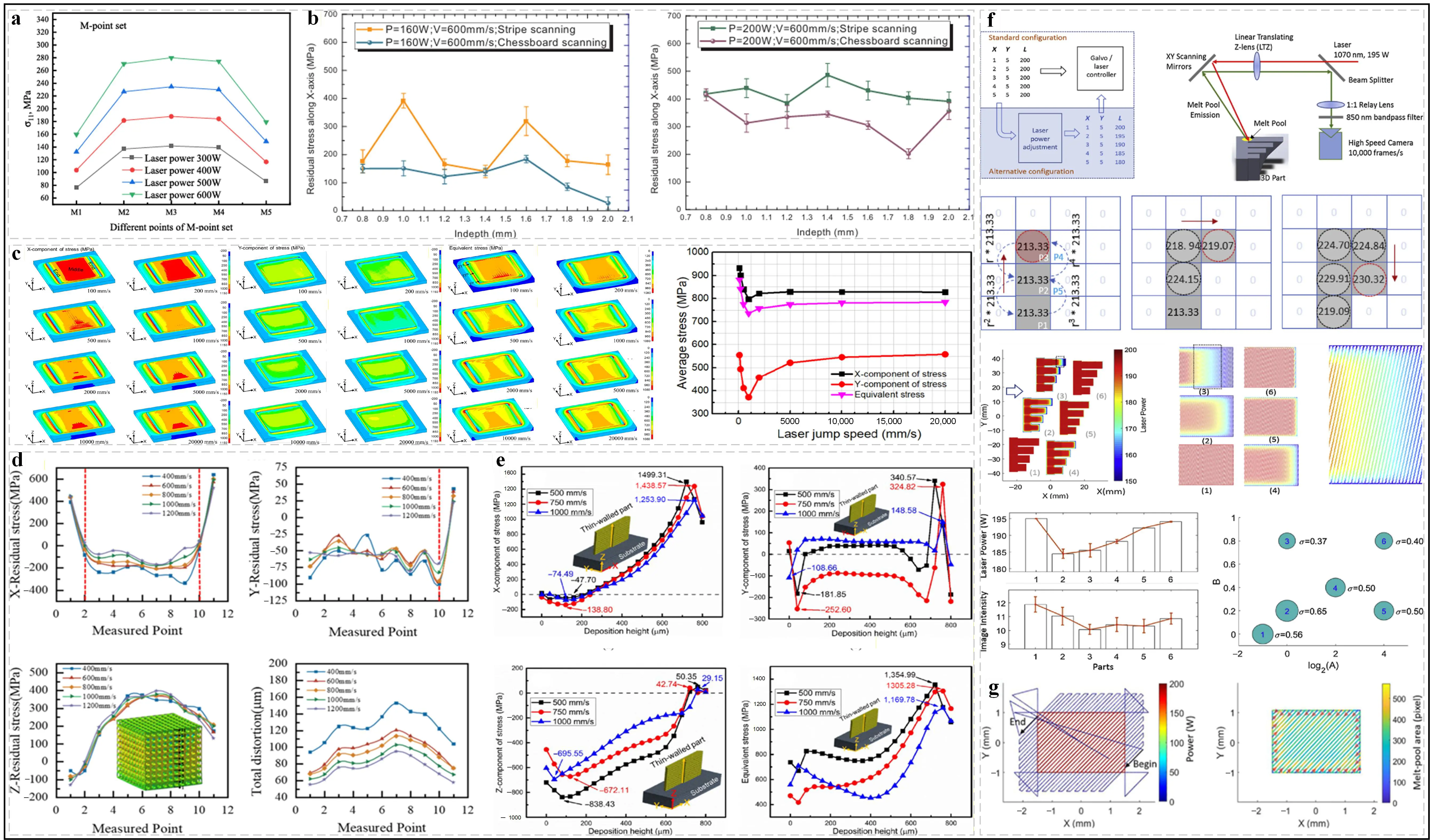
Figure 12. Laser power and scanning speed optimization. (a) RS under different laser power [207]; (b) comparison of in-depth RS distributions [208]; (c) The profiles of the X-component and Y-component of stress [12]; (d) RS distribution deformation at different scanning speeds [214]; (e) effect of the scan speed on the RS along the deposition direction [215]; (f) PBF-LB laser control [11]; (g) residual heat factor and laser power modulation [211].
5.1.2. Other Optimization Methods
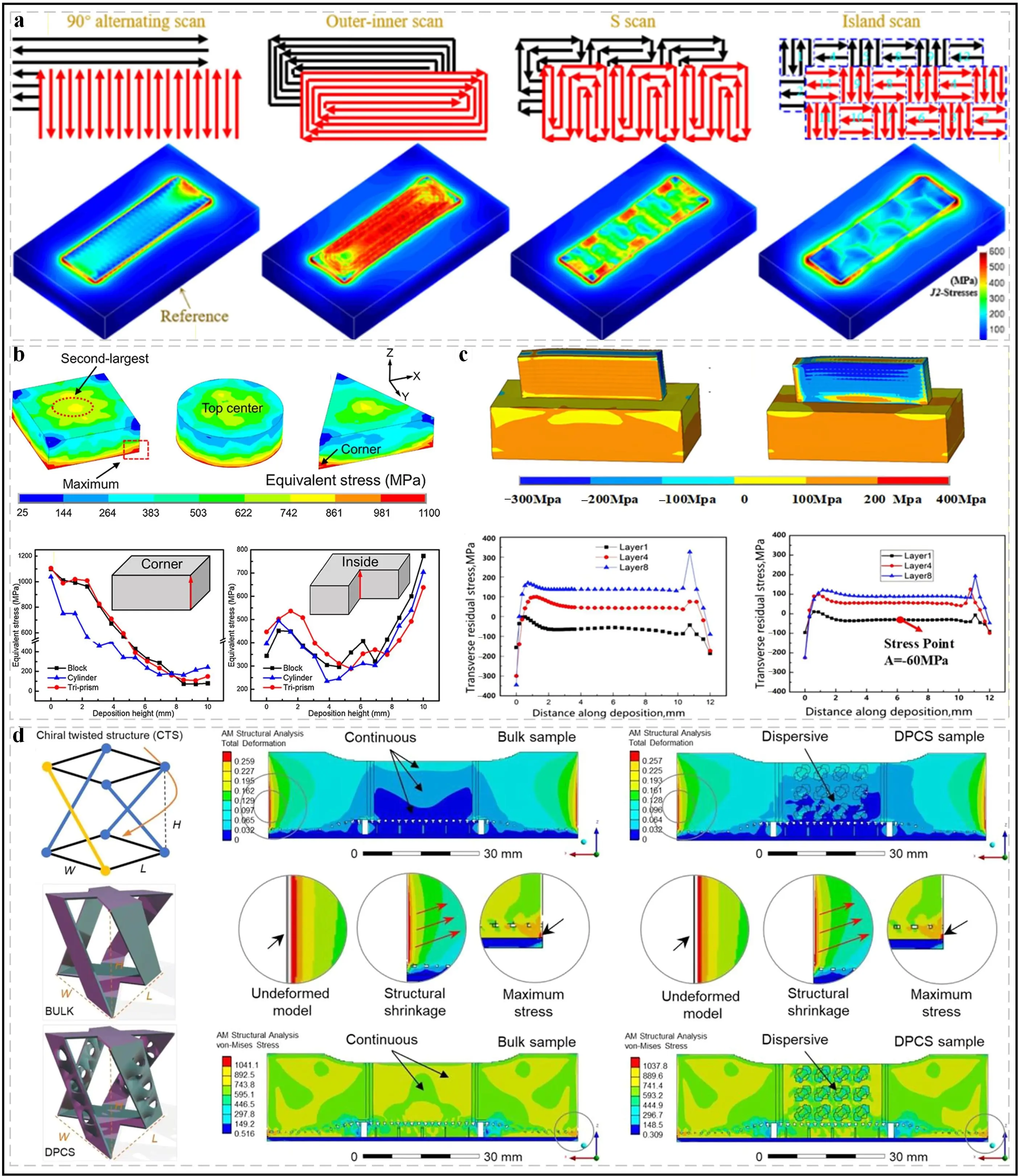
The influence of the scanning strategy on RS is a comprehensive effect on dimensions. A reasonable selection of the scanning strategy can not only reduce RS but also improve production efficiency and product quality [210]. Lu et al. [7] systematically analyzed the influence of four scanning strategies (90° alternating scan, outer-inner scan, island scan, and the S scan proposed) on the RS of DED components. As shown in Figure 13a, the island mode with shorter scan lines generates the lowest stress level, whereas the outer-inner scanning strategy, due to its longer path, shows higher stress accumulation. The 90° alternating scan and the island scan, with their shorter scan lines, produce the smallest vertical displacement and RS. Xu et al. [216] proposed a numerical method that integrates the scanning pattern with TO in parallel to design large laser-powder bed fusion (L-PBF) parts. A scanning pattern with more islands can provide the solver with more degrees of freedom, thereby more effectively reducing residual warpage and simultaneously enhancing structural stiffness. Chen et al. [217] developed a continuous laser scanning path optimization method and an adaptive level set adjustment strategy. The optimization applied to the L-shaped bracket indicates that by optimizing the scanning path, the maximum von Mises stress of the first and second layers was reduced by 11.3% and 7.20%, respectively.
In addition to the traditional optimization of process parameters, the optimization of the structure and shape of materials and substrates, as well as the introduction of new heat and cold sources, also have a significant effect on the optimization of RS [218]. Chen et al. [219] systematically compared the effects of arc-shaped structures and straight structures on the RS of L-PBF. As shown in Figure 13b, the maximum RS of the triangular prism structure with sharp corners (1106.0 MPa) is higher than that of the block (1099.2 MPa) and the cylindrical structure (1037.7 MPa) due to the high stress concentration factor and the tendency to experience local overheating. Sharp corners are an important factor in inducing cracking. In contrast, the cylindrical structure has a smooth transition, reducing the high-stress area. Therefore, using arc-shaped structures instead of straight, sharp corners can help reduce RS. Sun et al. [13] investigated the application of a thermomechanical protection structure based on a double-periodic continuous surface in L-PBF. Figure 13d shows that, compared with traditional solid tensile specimens, the doubly periodic continuous surfaces (DPCSs) structure can more effectively disperse deformation and stress distribution, which is conducive to stress release during the manufacturing process and alleviates out-of-plane deformation and warpage. Yan et al. [220] compared the effects of quasi-continuous wave (QCW) and continuous wave (CW) laser modes. As shown in Figure 13c, at the same power, the maximum RTS can be reduced from 340 MPa to 205 MPa by using the QCW mode, a reduction of approximately 40%, and the surface stress state changes from being dominated by tensile stress to being dominated by compressive stress.
The component geometric design and scanning strategy are the key process factors affecting the TRS in A/SHM. Optimizing the geometric structure and designing a reasonable scanning strategy can effectively control the heat input and temperature field, thereby significantly reducing the TRS and improving the performance and forming quality of the component.
5.2. Post-Processing Optimization
Researchers define the techniques for controlling and reducing RS in components after production as post-processing techniques, including annealing, hot isostatic pressing (HIP), and solution aging [221,222]. Generally, L-PBF parts undergo post-heat treatment cycles to reduce RS within the parts, although this increases the time and cost of the manufacturing process. These cycles prompt the material to respond to TRS, altering its mechanical properties without changing the material [221]. Through post-processing techniques, RS generated by rapid cooling rates and thermal gradients in A/SHM components can be effectively eliminated, thereby reducing the possibility of part warping or cracking and ensuring that the final properties of the alloy meet the specifications required for durability, reliability, and performance [223,224]. This section comprehensively introduces the optimization strategies of post-processing techniques for A/SHM components.
5.2.1. Annealing Treatment and Solution Aging Treatment
In A/SHM, the rapid melting and solidification of laser or electron beams lead to significant temperature gradients, causing TRS and phase-transformation stress, and forming high-density dislocations and lattice distortions. Annealing treatment heats the material to allow atoms to gain sufficient energy to diffuse, intensifying dislocation movement and leading to annihilation or recombination. At the same time, it eliminates temperature gradients and reduces stress caused by uneven thermal expansion. Thus, RS is reduced or even completely eliminated [225,226]. Marchese et al. [227] investigated the effects of different annealing temperatures on L-PBF fabricated Inconel 625. The average stress was not significantly changed by the 600 °C treatment, but the local stress on the side surface decreased from 780 MPa to 450 MPa. When the temperature was raised to 870 °C, the maximum principal stress dropped from 600 MPa to 340 MPa. After the 1150 °C treatment, the stress slightly increased (about 360 MPa), and a transition from tensile to compressive stress occurred at a depth of approximately 0.6 mm, which might be related to carbide formation. Gu et al. [228] studied the effect of annealing treatment on the RS of SiC/Al composites. In the center of the initial state specimen, along line A, the radial RS gradually decreases to zero from the center to the surface, while the tangential and normal RS do not change significantly. Along line B, from the center to the surface, the radial RS gradually decreases to zero, the tangential RS gradually changes from tensile to compressive stress, and the normal RS remains relatively constant under compressive stress. After annealing, the macroscopic RS is approximately zero, both near the center and the surface, indicating that annealing effectively eliminates macroscopic RS. Guo et al. [32] analyzed the effect of annealing temperature on the RS of DED-repaired superalloys. As shown in Figure 14a,b, annealing at 600–800 °C reduced the average stress by approximately 75% and the maximum stress by 63–77%, annealing at 900 °C was even more effective, reducing the average and maximum stress by approximately 87% and 84%, respectively. The mechanism varies with temperature: at 600 °C, it is mainly stress relaxation, at 800 °C, it is superimposed with plastic deformation, at 900 °C, recrystallization and creep further occur, achieving almost complete stress relief.
During the A/SHM process, the non-uniform temperature field and phase transformation volume changes caused by layer-by-layer deposition led to the accumulation of RTS. Solution treatment involves heating the metal to an appropriate temperature and holding it to allow alloying elements to dissolve fully and form a uniform solid solution, thereby eliminating local stress concentrations within the material due to rapid cooling or non-uniform temperature fields. Aging treatment involves the precipitation of solute atoms to form a dispersed second phase, thereby strengthening the material and adjusting the RS state, making the RS distribution more uniform. Solution aging reduces the RS in A/SHM components by homogenizing the microstructure and precipitating strengthening [221,229]. Liu et al. [38] proposed a novel hybrid AM process (USP + L-PBF) method. As shown in Figure 14c, aging treatment can partially reduce the tensile RS of L-PBF ultra-high strength aluminum alloy, while subsequent ultrasonic shot peening (USP) treatment can further convert it into beneficial compressive RS. The tensile and compressive stresses at different depths cancel each other out, improving the stress distribution. Zhan et al. [39] investigated the effect of solution temperature (890 °C, 930 °C, 980 °C, 1030 °C) on the RS of TC4 alloy prepared by LAM. As shown in Figure 14d, the RS increases slowly with the temperature rise below the Tβ (992 °C). After exceeding this temperature, the stress drops significantly. This is mainly related to the phase transformation behavior and the difference in stress relaxation ability of different microstructures. Tonelli et al. [40] systematically analyzed the effects of artificial aging and solution treatment on A357 alloy fabricated by L-PBF. As shown in Figure 14e, solution treatment at 200–300 °C can eliminate most of the RS, while a short period of artificial aging has a limited effect on reducing tensile stress. A longer holding time is required to more significantly relieve the stress.
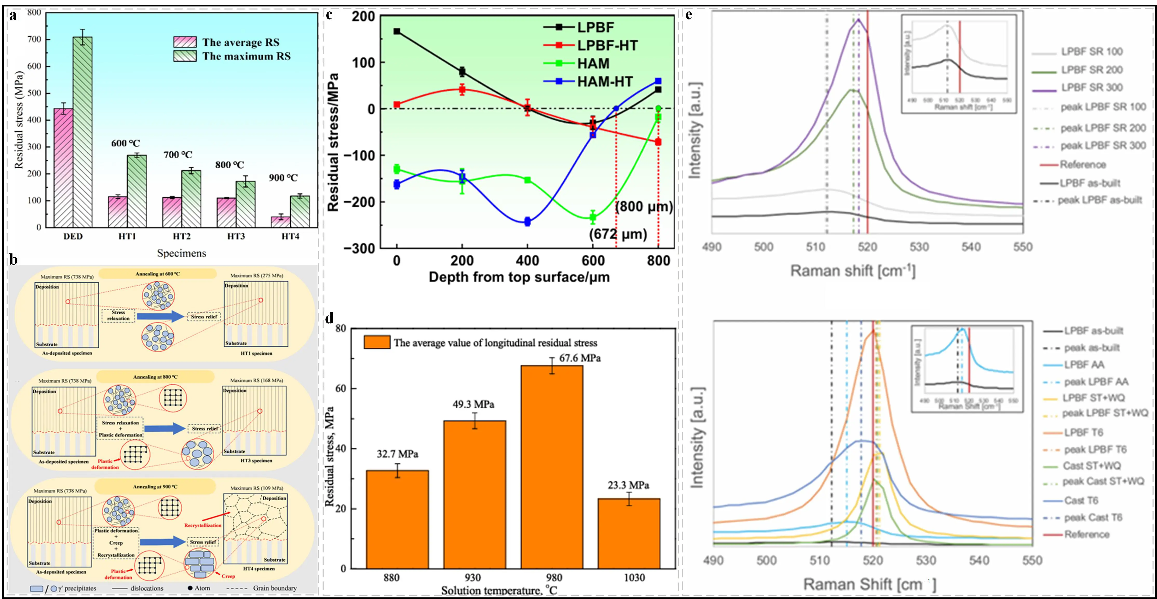
Figure 14. Annealing treatment and solution aging treatment optimization. (a) distribution diagram of RS in the as-deposited and annealed specimens [32]; (b) stress relief mechanism of annealing treatment at different temperatures [32]; (c) RS distributions of the L-PBF, LPBF-HT, HAM, and HAM-HT samples [38]; (d) the average longitudinal RS in TC4 specimen after HT [39]; (e) raman spectra of the Si frequency of heat-treated samples compared to the L-PBF as-built sample [40].
5.2.2. Other Post-Processing Methods
In addition to the common annealing treatment and solution aging treatment, post-treatment methods such as HIP and in-situ HT can also optimize the RS in the A/SHM process. Meanwhile, the rapid development of emerging field-assisted processes and LSP has shown unique advantages in optimizing and controlling RS [222,230]. This section will introduce the optimization and control of RS in A/SHM by other post-treatment methods in sequence.
HIP treatment, through the combined effect of high temperature and high pressure, causes creep deformation in the material under the high-temperature environment, releasing the RTS accumulated during the rapid solidification and thermal cycling in the AM process. The high pressure promotes the closure of internal pores and eliminates stress concentration sources, thereby significantly reducing the RS in the A/SHM process [231,232]. Homami et al. [233] quantitatively studied the effect of HIP on RS relaxation based on a numerical model of hyperbolic sine creep law and TRS analysis. Figure 15a shows the equivalent von Mises stress at points A and B under 700 °C HT in a conventional furnace and 700 °C, 100 MPa applied isostatic pressure. At the initial stage of furnace treatment, due to the limited plastic deformation, the RS decreases approximately linearly. As the yield stress decreases during heating, the material’s ability to maintain elastic deformation weakens, leading to a transition from elastic strain to plastic strain, and subsequently, the RS decreases. The reduction in von Mises stress during HIP is driven by the combined effects of creep and plastic deformation, which are enhanced by the synergy of high temperature and increased pressure. At the beginning of the HIP process, the von Mises stress at both points decreases linearly, with a greater reduction compared to HT. During the holding stage, the reduction in von Mises stress continues but at a slower rate. This is mainly due to the saturation of creep and the plastic deformation mechanism, that is, the limited development of creep strain and no additional plastic deformation. Under furnace conditions, the stress reduction at point A is limited to 118 MPa, and at point B to 4 MPa. However, the application of pressure in HIP leads to further stress relaxation, reducing the stress at point A to 92 MPa and almost eliminating the stress at point B (3 MPa). This comparison indicates that the additional driving force provided by pressure in HIP is crucial for enhancing plastic deformation and creep, thereby achieving more effective stress relaxation. Niu et al. [234] studied the effect of HIP on the micro-scale RS in nickel-based single crystal superalloys. Figure 15b shows the distribution of RS in the dendrite stem and dendrite arm regions before and after HIP treatment. The range of RS values at five positions in the dendrite stem is approximately −650 MPa to 680 MPa. In the x-direction, all stresses are tensile, with a fluctuation range of approximately 260 MPa. In the y-direction, all stresses are compressive, with a fluctuation range of approximately 270 MPa. The RS values in the dendrite arm region range from −720 MPa to 670 MPa, and the RS characteristics in the x and y directions are similar to those in the dendrite stem. After HIP treatment, the RS on the dendrite stem of the single crystal matrix decreased by nearly an order of magnitude, but the RS characteristics in the x and y directions remained unchanged. The RS on the dendrite arm also decreased significantly, but the properties in the x and y directions changed, which may be attributed to the extensive microstructure homogenization in the interdendritic region during HIP and HT. Quantitatively, the RS in the nickel-based single crystal alloy was significantly reduced to <100 MPa, especially the tensile RS, which is crucial for maintaining the stability of the mechanical properties of single crystal superalloys during use. Zhou et al. [235] proposed a deep cryogenic treatment (DCT) to reduce the RS in L-PBF components. As shown in Figure 15c, the finished sample surface had a large tensile RS. The equivalent RS was as high as 126.9 ± 14.8 MPa. The RS of the HT sample was 29.8 ± 3.2 MPa, a reduction of 76.5% in stress. HT eliminated the ultrafine microstructure obtained during L-PBF and simultaneously coarsened and homogenized the microstructure, thereby significantly reducing the RS. DCT reduced the RS to 34.6 ± 1.6 MPa, a reduction of approximately 72.7%. The principle is that DCT causes inconsistent volume contraction between the Al matrix and the eutectic-Si network, and that plastic deformation occurs during the soaking process, resulting in compressive RS that remains in the sample upon reheating to room temperature. Therefore, the remaining compressive RS ultimately offsets part of the initial tensile stress, leading to a reduction in RS. Adding an auxiliary thermal field in the AM process to reduce the thermal gradient and cooling rate can alleviate the TRS [230]. Ding et al. [236] experimentally analyzed and conducted FE simulations to study the effect of substrate preheating on the RS of laser direct energy deposition (LDED) fabricated 12CrNi2 steel. As shown in Figure 15d, the RS on the surface of 12CrNi2 low alloy steel decreased with the increase in preheating temperature. Bai et al. [237] used FE simulation to compare the effects of preheating and post-heating on the RS of deposited materials and proposed that preheating is more beneficial for eliminating RS, as shown in Figure 15e. Martina et al. [238] demonstrated that interlayer rolling at a force of 75 kN in Ti-6Al-4V walls can reduce the RS at the interface between the deposit and the substrate by 60%, as shown in Figure 15f. For LSP-assisted AM, LSP can change the RS state of LPBF-processed parts from tensile to compressive stress and significantly reduce the deformation of the parts [230], as shown in Figure 15g. Zhao et al. [239] established a simulation model to reveal the evolution of stress and strain during in-situ rolling-assisted WAAM. The results indicated that rolling increased the strain in the weld bead and reduced the RTS on the surface, as shown in Figure 15h. Shen et al. [240] used FE simulation to study the effect of induction HT on the RS of C-shaped steel components fabricated by WAAM. Figure 15i shows that the initial stress was concentrated at the corners, and induction HT eliminated the stress concentration at the corners, making the stress distribution more uniform.
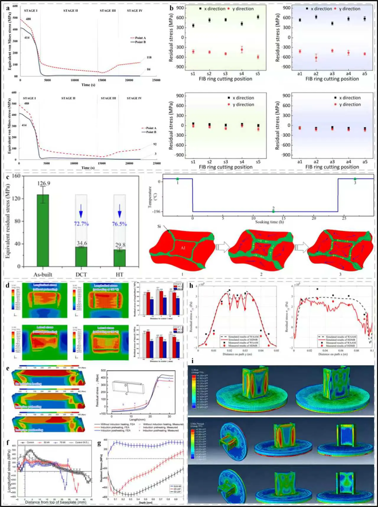
Figure 15. New post-processing optimization. (a) Equivalent von Mises stress [233]; (b) RS of as-casted nickel-based single-crystal superalloy and as-HIPed alloys [234]; (c) equivalent RS measured by hole-drilling method and schematic diagram of plastic deformation [235]; (d) RS distribution simulation in an LDED-built 12CrNi2 low alloy steel [236]; (e) RS distribution simulations of a WAAM-built ER70S-6 under different in-situ induction heating processes [237]; (f) interlayer rolling assisted WAAM Ti-6Al-4V [238]; (g) LSP assisted L-PBF 316 L [230]; (h) in-situ rolling assisted WAAM Inconel 718 [239]; (i) simulation results of stress field and variation of RS under the maximum stress principle [240].
5.3. Material Selection and Modification
Material selection determines the base level of RS in A/SHM, while material modification further optimizes or mitigates RS by regulating microstructure, composition, or interface characteristics [241,242]. The inherent physical, chemical, and mechanical properties of materials can directly affect the thermal gradient, phase transformation effect, and plastic deformation capacity during the A/SHM process, thereby determining the initial state of RS. Material modification, under the premise of basic material selection, alleviates RS through adjustments in microstructure, composition, or interface [243,244]. This chapter systematically introduces the application of new materials and the impact of material modification on the optimization of RS.
5.3.1. Application of Advanced Novel Materials
High-entropy alloys exhibit unique novel microstructures and excellent performance combinations due to the multi-principal element mixing entropy effect. By reducing the stacking fault energy through trace alloying, dislocations can be induced to shift from cellular slip to planar slip, and stacking faults/twins can be promoted to dissipate TRS. The nanocrystals and high-density dislocations formed during rapid solidification in L-PBF can disperse stress concentration [245,246]. Bui et al. [247] studied the deformation and processing mechanisms of nanocrystalline Ni–Co–Cr–Fe high-entropy alloys. As shown in Figure 16a, the von Mises stress rapidly rose to the maximum with the appearance of dislocations and then gradually decreased, indicating that dislocations led to stress release in the specimens. The von Mises stress of the Ni25Co25Cr30Fe20 specimen was always higher than that of the other specimens. Meanwhile, during the cutting process, the von Mises stress of the Ni30Co20Cr25Fe25 specimen was the lowest. For polycrystalline specimens, due to the ability of polycrystals to suppress dislocation propagation and transfer GB stress and strain, the von Mises stress value of single-crystal specimens was higher than that of polycrystalline specimens during the cutting process. Lin et al. [248] studied the effect of different brazing temperatures on the RS of the new material composed of Nb0.74CoCrFeNi2 eutectic high-entropy alloy filler connecting SiC and Mo. The FE analysis results in Figure 16b show that the presence of the Cr0.46Mo0.4Si0.14 phase was not conducive to the release of RS. With increasing brazing temperature, the content of the Cr0.46Mo0.4Si0.14 phase gradually decreased, which was beneficial for improving joint strength. At a brazing temperature of 1300 °C, the Cr0.46Mo0.4Si0.14 phase in the brazing seam almost disappeared, thereby completely eliminating the stress. Li et al. [249] showed ND and FE modeling to study the RS distribution in Co–Cr–Fe–Mn–Ni high-entropy alloy prepared by LMD. As shown in Figure 16c, the stress gradient was significant, and all stress components decreased gradually along the build direction. The compressive RS gradually decreased along the build direction, which could be attributed to the thermal constraints, complex thermal cycles, and different temperature gradients along the deposition direction during the LMD process. Sun et al. [250] improved the RS state by introducing in-situ Al alloying into the high-entropy alloy Co–Cr–Fe–Ni. As shown in Figure 16d, the minimum RS was obtained in the 0.5Al sample. For the 0.5Al sample, during the initial solidification process, Al was separated into the dendrite interstices/boundary regions, forming a continuous liquid film. After further cooling, the B2/body-centred cubic phase would appear as isolated islands, and due to thermal contraction, high tensile residual strain was generated. Under the combined effect of molar volume expansion and plastic deformation, they could effectively eliminate RS/strain. In some cases, if the proportion of the B2/body-centred cubic phase was high enough, they could transform the RS from tensile to compressive, which was very beneficial for reducing hot tearing. Yang et al. [30] proposed a model for predicting RS in thin-walled structures of SS316/IN718 FGMs fabricated by DED and studied the effect of material gradient angle on the RS of the component. Figure 16e shows that in the FGMs thin-walled structure dominated by vertical orientation, the maximum tensile RS is proportional to the material gradient angle (θ1). Conversely, increasing the material gradient angle (θ2) in the horizontally dominated thin-walled structure leads to greater compressive RS in the top region of the FGMs structure. This is due to the mismatch in CTE between SS316 and IN718, which restricts the thermal expansion of the top surface material. Additionally, because the material transition from SS316 to IN718 is smoother in the build direction, the RS fluctuation along the selected path in the build (Z) direction is less in the horizontally dominated FGMs wall than in the vertically dominated wall.
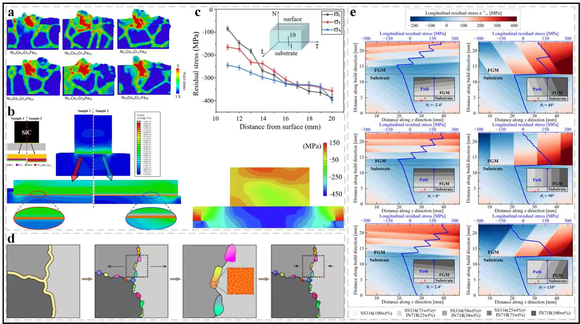
Figure 16. Optimization of New Material Applications. (a) The von Mises stress for various alloy compositions [247]; (b) FE analysis results [248]; (c) distribution of RS components in the LMDed- Co–Cr–Fe–Mn–Ni HEA specimen [249]; (d) schematics of RS minimization for Al0.5CoCrFeNi sample [250]; (e) effects of material transitional angles on the RS distributions [30].
5.3.2. Material Modification
Material modification achieves the optimization of material’s thermal physical properties and mechanical response capabilities by actively regulating the microstructure, composition distribution, or interface characteristics of metals, thereby achieving precise alleviation or directional regulation of RS in A/SHM [251,252]. Chen et al. [253] designed and constructed a WC/Co composite modified layer on the surface of diamond, and uniformly mixed it with the typical CuSn alloy binder. FE simulation was used to compare and analyze the distribution characteristics and changes of RS before and after interface modification. Figure 17a,c shows that the WC/Co composite coating on the surface of diamond particles significantly improved the interface bonding state with the CuSn matrix. The presence of WC/Co coating not only reduced the RS at the interface of the diamond composite material but also narrowed the impact range of high RS near the interface. The WC/Co coating reduced the overall RS of the composite material, and the maximum RS at the interface was 11.8% lower than that of the uncoated material. The WC/Co composite coating first undergoes plastic deformation during cooling, reducing the accumulation of RS near the interface between diamond and CuSn matrix, thereby reducing the influence range of RS and high stress at the interface, and effectively playing the role of a stress elimination mechanism. Wang et al. [254] studied the effect of Cr element on RS in Cu–Al2O3 composite materials. Figure 17b shows the RS distribution of copper-based composite materials along the x-axis direction. The interface RS of Cu–Al2O3 (39.4 MPa) was higher than that of Cu–Cr (7.67 MPa) and Cr–Al2O3 (33.6 MPa). The higher interface RS in Cu–Al2O3 composite material led to interface debonding, resulting in interface microcracks. On the other hand, the Cu–Cr–Al2O3 composite material with reduced interface RS could withstand higher applied stress. Therefore, the discontinuous nanoscale Cr transition zone between the Cu matrix and Al2O3 nanoparticles reduced the interface RS, improved interface bonding, and ultimately increased the hardness and compressive properties of Cu–Cr–Al2O3 composite materials. Austin et al. [255] proposed a new method to control the release of RS in fused filament fabrication printing structures by incorporating nanoscale additives into filament raw materials. Figure 17d,e shows that these additives would affect the nanoscale and mesoscopic structure of polymer chains, ultimately changing the degree of relaxation of the overall printing in the annealing process. The observed continuous relaxation of the printed overall structure during thermal annealing led to y-axis contraction and z-axis elongation. The degree of RS release depends on the formulation of the raw materials used for the printed overall structure and whether it is exposed to in-situ ultraviolet illumination during the printing process. In samples where photoinitiators or graphene raw materials were used for printing and exposed to ultraviolet radiation during the printing process, an irreversible reduction in thermal strain was observed (related to the inhibition of RS release). This change in RS is attributed to chemical reactions that limit the movement of polymer chain segments within the structure. Micheal et al. [256] studied the effect of ultrasonic nano-crystal surface modification on RS in ATI718plus alloy. The static load of UNSM1 was 20 N, with an amplitude of 8 μm, and UNSM2 was 40 N with an amplitude of 16 μm, with other conditions being equal. Figure 17f shows that the RS depth in the X and Y directions of the two ultrasonic nanocrystal surface modification (UNSM) conditions exhibits a similar trend, but the amplitude has changed. The surface RS of UNSM1 was approximately −1209 MPa, and that of UNSM2 was approximately −1376 MPa. The amplitude of RS near the surface area increased slightly and gradually decreased with depth. The surface RS after UNSM treatment was relatively high, and after approximately 250 μm, its amplitude gradually decreased to a more or less constant value. Overall, the RS, hardening, and full-width at half-maximum size of UNSM2 were slightly higher than those of the equivalent depth in the other two cases. Gill et al. [257] studied the effects of LSP, cavitation shotless peening, and UNSM on the RS field of nickel-based superalloys. Figure 17g shows that the RS field introduced by LSP is close to the isotropic double axis, and the RS distributions in the two directions differ little within the first 150 μm. Cavitation shotless peening introduces an isotropic double-axis RS field. UNSM introduces a non-isotropic stress field, with significant differences in the stress size on the surface, although such differences only occur within the first 150 μm. Maleki et al. [35] studied the effects of peening, laser impact peening, and ultrasonic nano-crystal surface modification on RS and fatigue strength of Inconel 718. Figure 17h,i show that the compressive RS induced by UNSM and severe shot peening at a depth of 500 μm is less than −50 MPa, while the compressive RS induced by LSP at the same depth is approximately −200 MPa. The results indicate that UNSM treatment significantly increases the compressive RS field in the surface and internal depths. After UNSM, severe shot peening and LSP treatments, each treatment using the highest kinetic energy resulted in a fatigue life increase of 5.25 times, 3.71 times, and 3.21 times, respectively. This trend can be attributed to the compressive RS and grain refinement at the surface layer.
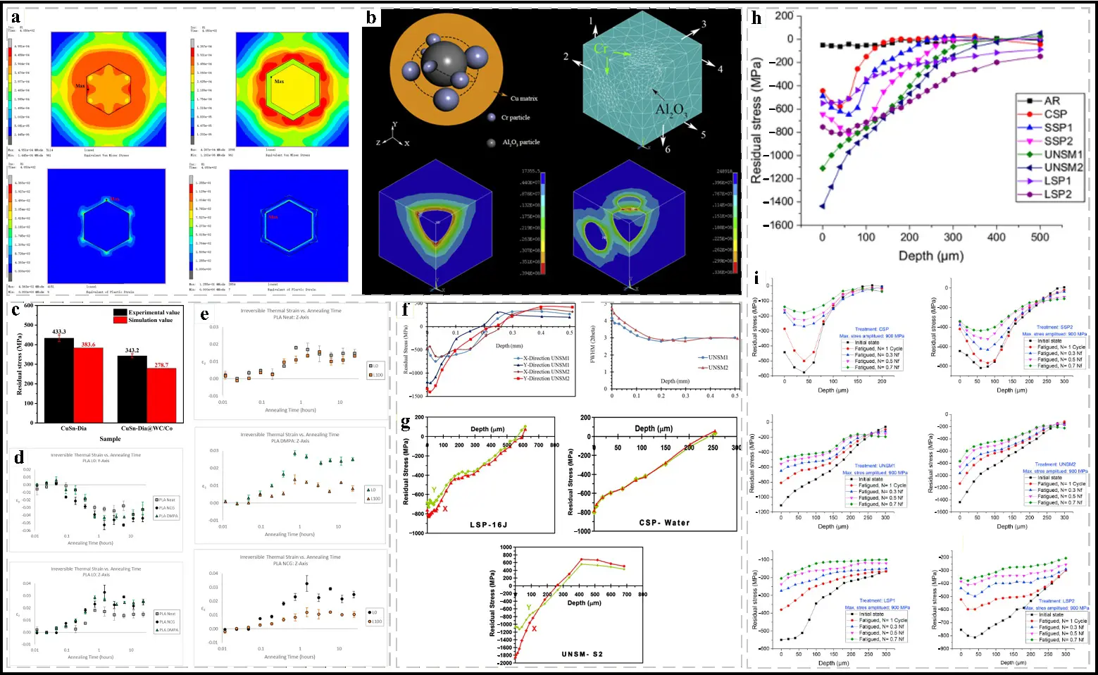
Figure 17. Optimization of material modification. (a) RS and equivalent plastic strain distribution after sintering cooling [253]; (b) contour of RS field for interfaces in Cu–Al2O3 and Cu–Cr–Al2O3 composite [254]; (c) comparison of measured and simulated RS [253]; the variation of irreversible thermal strain with annealing time: (d) before irradiation, (e) after irradiation [255]; (f) RS in both X-direction and Y-direction [256]; (g) RS vs. Depth for two principal axes [257]; (h) distribution of the compressive RS [35]; (i) distributions of the compressive RS in the fatigued specimens [35].
6. Application Cases of Residual Stress in Additive/Subtractive Hybrid Manufacturing
The thermal gradient during the A/SHM process leads to the concentration of RS, which may cause structural deformation, crack propagation, and even fatigue failure, severely restricting its application in high-precision fields such as aerospace, medical devices, and automotive manufacturing [258,259]. With the rapid development of TO algorithms and AI, which provides significant assistance in controlling the RS during the optimization of the A/SHM process and expanding its application fields [5], as shown in Figure 18a,b. Space-time TO incorporates the manufacturing sequence into the algorithm through pseudo-time field encoding and a layer-by-layer accumulation process, combined with the anisotropic inherent strain model to predict the stress distribution, ultimately achieving the global regulation of RS [260]. The RS—process parameter mapping relationship based on artificial neural networks can predict risks before printing and optimize the path [5], as shown in Figure 18c. This chapter will systematically explain the influence of RS from three major fields: aerospace, biomedicine, and automotive manufacturing.
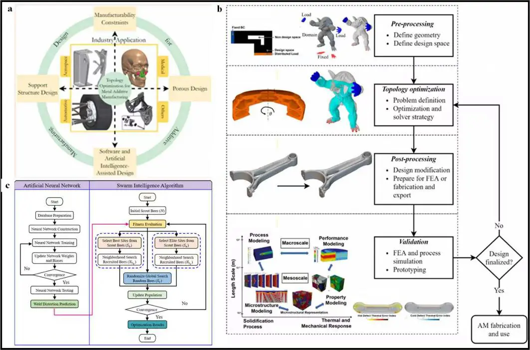
6.1. Applications in the Aerospace
Aerospace parts are usually made of difficult-to-machine materials such as titanium alloys and aluminum alloys. During the AM process, the huge temperature gradients generated by local melting and solidification can lead to extremely high RS. When these stresses exceed the yield strength of the material, they will directly cause the parts to crack during the manufacturing process or to undergo delayed cracking when subjected to loads during service, seriously threatening flight safety. The core components, such as aircraft engine blades and fuselage load-bearing parts are subjected to cyclic loads for a long time, and the RS will superimpose with external loads, forming stress concentration on the surface or at defects, accelerating the initiation and expansion of fatigue cracks, and significantly shortening the service life of the parts [262,263]. Zhang et al. [264] proposed an active method in the process to control the influence of bulk RS and machining induced RS on the deformation of aerospace thin-walled components. This technology is based on balancing the deformation generated by bulk RS and machining induced RS after each cutting with the equivalent deformation produced by the external force applied by the active fixture system. Compared with the zero-sum and total process relaxation strategies, the distortion was reduced by 18.3% and 42.9%, respectively. Dixit et al. [41] manufactured and tested a new generation liquid-to-liquid heat exchangers using a gyroscope lattice structure. Compared with traditional heat exchangers, the new design performs better in controlling TRS and thermal performance stability, as shown in Figure 19a. Ji et al. [265] found that in the FSW process of Al–Li alloy, using liquid nitrogen trailing cooling, the peak temperature of the weld seam decreased from 350 °C to 250 °C, and the longitudinal RS decreased by 23.8%. Hanush et al. [266] studied the optimization of RS in aerospace brackets using integrated TO design and A/SHM. Figure 19c shows that the optimized bracket weight was reduced by 44.8%, the safety factor standard required under all load conditions was 2–2.3, and the SLM process parameters were 80 W of laser power, a scanning speed of 1000 mm/s, and a cabin surface spacing of 90 μm, which minimized the RS.
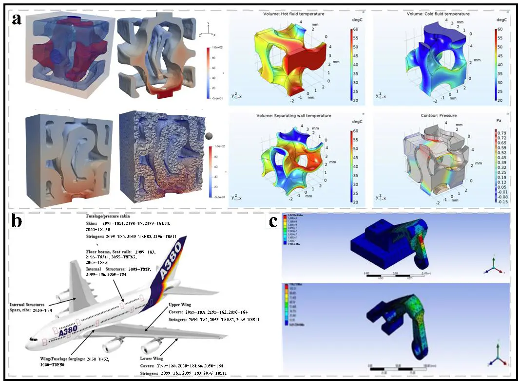
6.2. Application in the Field of Medical Devices
Figure 20 shows the practical application of A/SHM in the medical field. Compared with traditional manufacturing techniques, A/SHM technology is transforming the design and manufacturing of medical devices by reducing RS on implant surfaces and on complex surgical instruments, offering unprecedented freedom to create personalized patient solutions and to manufacture intricate structures [269,270]. The surface RS concentration areas of traditional mechanically processed titanium alloy implants are prone to microcrack propagation, leading to an imbalance in the stress distribution at the interface between the implant and bone tissue. Compared with traditional manufacturing processes, A/SHM implants have significantly improved biocompatibility, such as tracheal, ankle-foot orthoses, and heart stents [271,272]. In the A/SHM process of ankle-foot orthoses, researchers analyzed the influence of the printing direction on RS and deformation through FE simulation [43]. Figure 20a indicates that 45° printing can enhance the mechanical properties of the orthosis because the forces applied during use are mainly horizontal. Theoretically, the 45° direction can achieve better stress distribution throughout the printed structure, thereby increasing mechanical resistance. Figure 20b shows that in the design of intraosseous mandibular implants, the von Mises stress values of the fully non-lattice (~40 MPa) and fully lattice (~15 MPa) design models are both lower than the yield strength of Ti-6Al-4V, with stress concentration in the angle area of the mandibular implant [273]. Figure 20c shows that in the A/SHM process of tibial components, the design of support structures plays an important role in reducing deformation. Block structures are more effective in reducing deformation compared to rod structures [274]. Modifying A/SHM parameters can ensure a stable oxide layer on titanium alloy implants, thereby improving biocompatibility [275].
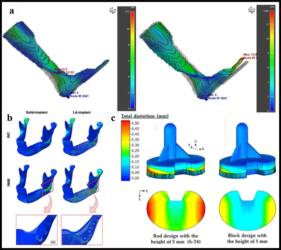
6.3. Applications in Automobile Manufacturing
In the current automotive manufacturing industry, the automotive alloy parts fabricated by A/SHM are mainly used to reduce weight, thereby achieving the goal of lowering the overall fuel consumption, power consumption, and air resistance of vehicles, and enabling vehicles to fully exert their performance [276,277]. Sun et al. [44] developed a FE-based sequential coupling method to optimize the thin-walled structures used in automotive parts. As shown in Figure 21b, the crashworthiness design without considering the residual forming effect and the fluctuations of design variables and manufacturing parameters will lead to unreliable or even infeasible designs. Wang et al. [278] conducted multi-objective optimization on the front longitudinal beam made of H340LAD high-strength steel by coupling stamping and crash analysis. In the crash simulation considering the residual stamping data, the trend of increasing crushing force with deformation is greater compared to that without considering the residual stamping data. The analysis results fully demonstrate that in the design stage of body components, the stamping history should be considered to accurately evaluate the crashworthiness, as shown in Figure 21c. Seobin et al. [279] proposed a ML-driven intelligent fixture. It enables the detection of micro-level quality issues caused by RS during production without interrupting the continuous manufacturing process. This method has been successfully validated on a commercial vehicle production line, achieving an accuracy rate of 97.7%, as shown in Figure 21d. In summary, RS is a key issue that must be properly addressed to enable the large-scale, high-reliability application of metal AM technology in the automotive field. Through full-process collaborative control of design, process, simulation, and post-processing, RS can be effectively controlled, thereby fully leveraging the huge potential of A/SHM in manufacturing complex, lightweight, and high-performance automotive parts [280,281].
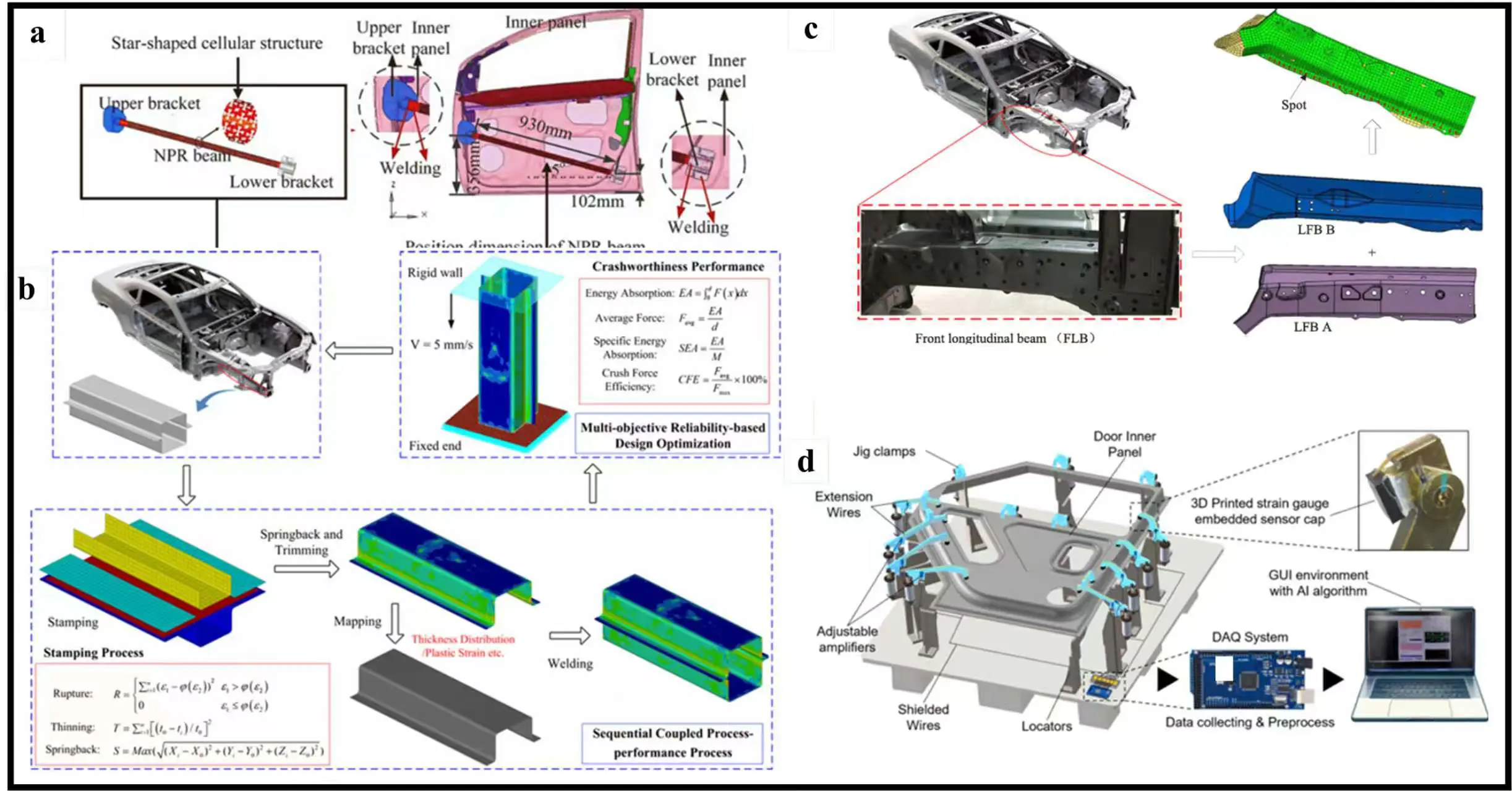
Figure 21. Applications in automobile manufacturing. (a) Anti-collision beam with negative Poisson’s ratio constructed from Re-entrant structures for automotive applications [277]; (b) the schematic of sequentially coupled stamping and crushing simulation [44]; (c) schematic of vehicle front longitudinal beam [278]; (d) hardware system of the smart welding jig [279].
7. Conclusions
This paper introduces the characteristics of RS in the A/SHM manufacturing process and investigates the distribution law of the stress field during fabrication. The objective is to achieve an in-depth understanding of fundamental research on RS in components fabricated via the A/SHM process, as well as to elucidate the mechanism by which process parameters influence the formation and distribution of RS. Following a discussion on the formation mechanism of RS and the characterization of the stress field, the selection of appropriate process parameters can effectively control RS, enhance mechanical properties, and meet the quality and performance requirements of formed components, as shown in Figure 22. Finally, the basic theory of the A/SHM process is presented, and the following conclusions are drawn:
- (1)
-
In A/SHM technology, RS primarily arises from significant temperature gradients and is influenced by factors such as thermal history, phase transformations, crystal structure, and differences in the material’s coefficient of thermal expansion. Its characteristics include multi-source superposition, anisotropy, interface concentration, and coupling among thermal-mechanical-microstructure effects. The evolution pattern of A/SHM stress is as follows: during the AM stage, stress generation is dominated by thermal accumulation, during the SM stage, relaxation and redistribution occur, while alternating processing between layers enables dynamic control, ultimately affecting the dimensional accuracy and mechanical properties of the component.
- (2)
-
In the A/SHM process, interlayer milling actively controls RS through a deposition-milling-deposition cycle: ultrasonic rolling introduces compressive stress up to 0.4 mm deep, high-temperature milling reduces tensile stress, and 30-s intermittent cooling decreases peak stress from 458 MPa to 372 MPa, while low-temperature intermittent cooling converts tensile stress into compressive stress with a 41% reduction. Additionally, stress can be regulated by controlling material properties, process parameters, geometry, and environmental conditions: increasing laser energy density helps reduce RS, scanning strategies influence temperature gradients and melt pool behavior, and different materials modulate interface stress distribution, thereby affecting component performance.
- (3)
-
Measuring RS evolution in A/SHM is highly challenging, with diverse techniques available: XRD and ND rely on changes in interplanar spacing, with ND offering greater penetration depth, the drilling method is semi-destructive and low-cost, commonly used for model validation, contour methods infer stress by analyzing deformation after cutting; nanoindentation is efficient and non-destructive but requires further refinement of its models, and magnetic memory detects stress concentration zones. In recent years, closed-loop prediction systems integrating multi-source sensing and ML, such as support vector regression, deep learning, and physics-guided models, have been developed, significantly improving prediction efficiency. However, data-driven approaches still face limitations, including inconsistent data quality, lack of unified calibration standards, and poor model generalizability.
- (4)
-
In traditional process optimization, the lowest RS can be achieved using a scanning speed of 1000 mm/s, a layer thickness of 60 μm, moderate laser power, and a short-path island scanning strategy. Interface stress can be further optimized by modifying the material-matrix structure, altering its properties, and controlling the coefficient of thermal expansion. Regarding high-temperature treatments: annealing enhances stress relaxation as temperature increases; solution aging promotes stress homogenization; hot isostatic pressing reduces porosity and stress concentrations; and introducing auxiliary fields enables control of phase transformation and thermal history, thereby improving the stress state and mechanical properties.
The core development direction for RS control in future A/SHM lies in establishing an integrated intelligent closed-loop system that encompasses real-time sensing, multi-scale modeling, intelligent prediction, and closed-loop control, enabling a paradigm shift from passive compensation to active regulation. Digital twin, as a virtual-physical mapping platform, supports dynamic calibration of processing parameters and ultra-real-time simulation by integrating multi-physics models of thermal-mechanical-microstructural behavior with real-time sensor data, providing a high-fidelity virtual mirror for stress control. AI-based stress prediction leverages graph attention networks, temporal convolutional networks, and physics-informed neural networks to increase prediction speed by thousands of times while maintaining accuracy, making in-situ stress perception feasible. Combined with Bayesian optimization and reinforcement learning, AI is evolving from surrogate models into intelligent decision engines. Multi-scale coupled simulation bridges microscopic dislocation slip and precipitate distribution with macroscopic temperature/stress fields, achieving a balance between computational efficiency and accuracy through an improved dynamic intrinsic strain method. By embedding microscale mechanisms into the FE framework via user-defined material subroutines, it enables cross-scale predictive capabilities. Real-time stress control and closed-loop process management integrate in-situ XRD, 3D-DIC, and synchrotron radiation monitoring techniques to form a sense–analyze–decide–act feedback loop: online acquisition of thermal, mechanical, and deformation signals is rapidly inverted using edge computing and AI models to determine stress states, dynamically adjusting laser power, scanning strategies, interlayer treatments, and SM intervention timing to achieve adaptive manufacturing. These technological dimensions are not developed in isolation but are deeply interconnected: digital twins provide validation environments for AI, AI endows digital twins with ultra-real-time prediction capabilities, and physical mechanisms revealed by multi-scale simulations inject prior knowledge into AI models, while the closed-loop system integrates all these capabilities. With the convergence of frontier technologies such as 4D printing, synchrotron radiation, and strong magnetic fields, precise prediction and active control of RS will fundamentally expand the application boundaries of A/SHM in high-end manufacturing sectors, including aerospace, automotive, and biomedical industries, unlocking design freedom and performance potential, and driving the transformation of manufacturing toward intelligent, high-precision, and highly reliable production.
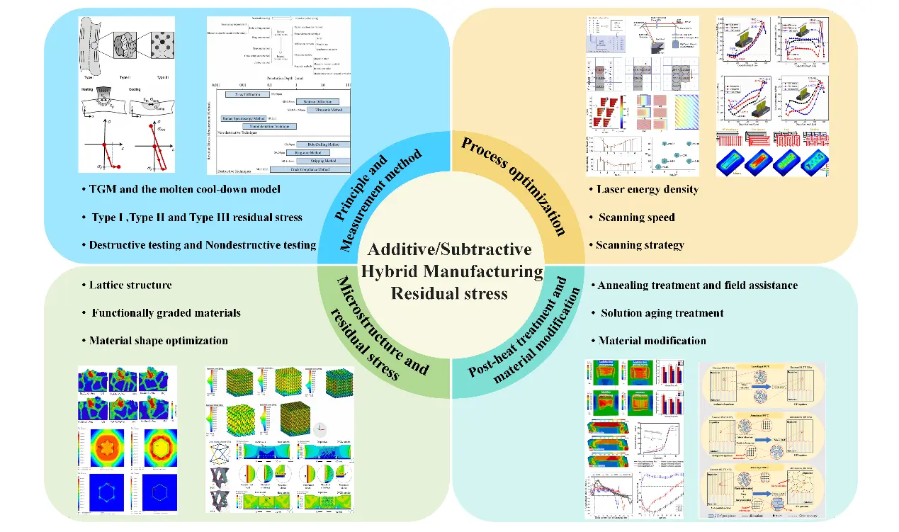
Statement of the Use of Generative AI and AI-Assisted Technologies in the Writing Process
During the preparation of this work, the authors used Gemini (Google) to improve the clarity and accuracy of English grammar and language expression. After using this tool, the authors reviewed and edited the content as needed and take full responsibility for the content of the published article.
Acknowledgments
We would like to express our gratitude to the laboratory staff of the Department of Mechanical Engineering at Qilu University of Technology for providing administrative and technical assistance.
Author Contributions
Conceptualization: S.Y., Y.Y. (Yuying Yang) and S.Q.; Methodology: S.Y., Y.Y. (Yuying Yang), Z.C. and Y.W.; Software: S.Y., A.O. and C.X.; Validation: S.Q., Y.Y. (Yongqian Yang), G.W., C.Q., B.S., J.G., T.G. and X.W.; Formal Analysis: S.Y., Z.C. and Y.W.; Investigation: S.Y., A.O. and C.X.; Resources: G.W., C.Q., B.S., J.G., T.G. and X.W.; Data Curation: S.Y., Y.Y. (Yuying Yang) and S.Q.; Writing—Original Draft: S.Y.; Writing—Review & Editing: Y.Y. (Yuying Yang), S.Q., and all other authors; Visualization: S.Y. and A.O.; Supervision: Y.Y. (Yuying Yang) and S.Q.; Project Administration: Y.Y. (Yuying Yang) and S.Q.; Funding Acquisition: Y.Y. (Yuying Yang) and S.Q.
Ethics Statement
Not applicable.
Informed Consent Statement
Not applicable.
Data Availability Statement
Data will be made available on request.
Funding
This study was supported by the National Natural Science Foundation of China (No. 52305475 and No. 52305484), the China Postdoctoral Science Foundation (No. 2024M761876), the Taishan Scholars Program (No. tsqn202408242), the Youth Innovation Team Program of Universities in Shandong Province (No.2024KJH166), Science, Education and Industry Integration Innovation Pilot Project from Qilu University of Technology (Shandong Academy of Sciences) (No. 2025QZJH03), Key Laboratory of High-effciency and Clean Mechanical Manufacture at Shandong University, Ministry of Education, and Young Scholars Future Program of Shandong University.
Declaration of Competing Interest
The authors declare that they have no known competing financial interests or personal relationships that could have appeared to influence the work reported in this paper.
References
- Khan S, Al Rashid A, Muhammad J, Ali F, Koç M. 3D Printing Technology for Rapid Response to Climate Change: Challenges and Emergency Needs. Intell. Sustain. Manuf. 2024, 1, 10004. DOI:10.35534/ism.2024.10004 [Google Scholar]
- Li Z, Qu S, Sun Y, Gong Y, Chu D, Yao P, et al. Robot Grinding: From Frontier Hotspots to Key Technologies and Applications. Intell. Sustain. Manuf. 2025, 2, 10027. DOI:10.70322/ism.2025.10027 [Google Scholar]
- Yang Y, Zong J, Qu S, Xiao G, Xu C. Effects of interlayer milling on the interfacial characteristics and mechanical properties of 316 L/IN718 functionally graded materials. J. Mater. Process. Technol. 2026, 354, 119384. DOI:10.1016/j.jmatprotec.2026.119384 [Google Scholar]
- Qian C, Zhang Y, Liu Y, Wang Z. A cloud service platform integrating additive and subtractive manufacturing with high resource efficiency. J. Clean. Prod. 2019, 241, 118379. DOI:10.1016/j.jclepro.2019.118379 [Google Scholar]
- Ibhadode O, Zhang Z, Sixt J, Nsiempba K, Orakwe J, Martinez-Marchese A, et al. Topology optimization for metal additive manufacturing: Current trends, challenges, and future outlook. Virtual Phys. Prototyp. 2023, 18, e2181192. DOI:10.1080/17452759.2023.2181192 [Google Scholar]
- Popineau V, Célino A, Péron M, Baley C, Le Duigou A. Understanding the effect of hygroscopic cycling on the internal stress and stiffness of natural fibre biocomposites. Compos. Part A Appl. Sci. Manuf. 2022, 158, 106995. DOI:10.1016/j.compositesa.2022.106995 [Google Scholar]
- Lu X, Cervera M, Chiumenti M, Lin X. Residual Stresses Control in Additive Manufacturing. J. Manuf. Mater. Process. 2021, 5, 138. DOI:10.3390/jmmp5040138 [Google Scholar]
- Sebbe N, Fernandes F, Sousa V, Silva F. Hybrid Manufacturing Processes Used in the Production of Complex Parts: A Comprehensive Review. Metals 2022, 12, 1874. DOI:10.3390/met12111874 [Google Scholar]
- Dávila J, Neto P, Noritomi P, Coelho R, da Silva J. Hybrid manufacturing: A review of the synergy between directed energy deposition and subtractive processes. Int. J. Adv. Manuf. Technol. 2020, 110, 3377–3390. DOI:10.1007/s00170-020-06062-7 [Google Scholar]
- Stavropoulos P, Bikas H, Avram O, Valente A, Chryssolouris G. Hybrid subtractive–additive manufacturing processes for high value-added metal components. Int. J. Adv. Manuf. Technol. 2020, 111, 645–655. DOI:10.1007/s00170-020-06099-8 [Google Scholar]
- Yeung H, Lane B, Fox J. Part geometry and conduction-based laser power control for powder bed fusion additive manufacturing. Addit. Manuf. 2019, 30, 100844. DOI:10.1016/j.addma.2019.100844 [Google Scholar]
- Chen C, Xiao Z, Zhang W, Wang Y, Zhu H. Effect of laser jump speed on temperature distribution and thermal stress in laser powder bed fusion. Opt. Laser Technol. 2021, 142, 107275. DOI:10.1016/j.optlastec.2021.107275 [Google Scholar]
- Sun J, Gu D, Lin K, Yuan L, Sun J, Wang R, et al. Laser additive manufacturing of a novel NiTi doubly periodic continuous surface for dispersing in-plane stresses and improving thermo-mechanical protection. Addit. Manuf. 2025, 98, 104643. DOI:10.1016/j.addma.2025.104643 [Google Scholar]
- Qu S, Li L, Yang Y, Sun Y, Pang S, Yin G, et al. Surface roughness and damage evaluation of carbon fiber reinforced silicon carbide composites after laser ablation treatment and subsequent grinding. J. Eur. Ceram. Soc. 2026, 46, 118082. DOI:10.1016/j.jeurceramsoc.2025.118082. [Google Scholar]
- Parlevliet P, Bersee H, Beukers A. Residual stresses in thermoplastic composites—A study of the literature—Part I: Formation of residual stresses. Compos. Part A Appl. Sci. Manuf. 2006, 37, 1847–1857. DOI:10.1016/j.compositesa.2005.12.025 [Google Scholar]
- Bruggeman K, Klingbeil N, Palazotto A. Residual Stress Generation in Additive Manufacturing of Complex Lattice Geometries. J. Mater. Eng. Perform. 2024, 33, 4088–4105. DOI:10.1007/s11665-024-09229-5 [Google Scholar]
- Li P, Gong Y, Wen X, Xin B, Liu Y, Qu S. Surface residual stresses in additive/subtractive manufacturing and electrochemical corrosion. Int. J. Adv. Manuf. Technol. 2018, 98, 687–697. DOI:10.1007/s00170-018-2283-4 [Google Scholar]
- Parry L, Ashcroft I, Wildman R. Understanding the effect of laser scan strategy on residual stress in selective laser melting through thermo-mechanical simulation. Addit. Manuf. 2016, 12, 1–15. DOI:10.1016/j.addma.2016.05.014 [Google Scholar]
- Guo J, Fu H, Pan B, Kang R. Recent progress of residual stress measurement methods: A review. Chin. J. Aeronaut. 2021, 34, 54–78. DOI:10.1016/j.cja.2019.10.010 [Google Scholar]
- Li C, Liu Z, Fang X, Guo Y. Residual Stress in Metal Additive Manufacturing. Procedia CIRP 2018, 71, 348–353. DOI:10.1016/j.procir.2018.05.039 [Google Scholar]
- Bartlett J, Li X. An overview of residual stresses in metal powder bed fusion. Addit. Manuf. 2019, 27, 131–149. DOI:10.1016/j.addma.2019.02.020 [Google Scholar]
- Qu S, Yao P, Gong Y, Yang Y, Chu D, Zhu Q. Modelling and grinding characteristics of unidirectional C–SiCs. Ceramics International. 2022, 48, 8314–8324. DOI:10.1016/j.ceramint.2021.12.036. [Google Scholar]
- Sun C, He P, Hu Z, Liang X. Metallurgical Characteristics of 316L Stainless Steel by Laser Additive Manufacturing. Intell. Sustain. Manuf. 2024, 1, 10012. DOI:10.35534/ism.2024.10012. [Google Scholar]
- Fang Z, Wu Z, Huang C, Wu C. Review on residual stress in selective laser melting additive manufacturing of alloy parts. Opt. Laser Technol. 2020, 129, 106283. DOI:10.1016/j.optlastec.2020.106283 [Google Scholar]
- Liu C, Lin C, Wang J, Wang J, Yan L, Luo Y, et al. Residual stress distributions in thick specimens excavated from a large circular wire+arc additive manufacturing mockup. J. Manuf. Process. 2020, 56, 474–481. DOI:10.1016/j.jmapro.2020.05.007 [Google Scholar]
- Mercelis P, Kruth J. Residual stresses in selective laser sintering and selective laser melting. Rapid Prototyp. J. 2006, 12, 254–265. DOI:10.1108/13552540610707013 [Google Scholar]
- Wang C. Simultaneous optimization of build orientation and topology for self-supported enclosed voids in additive manufacturing. Comput. Methods Appl. Mech. Eng. 2022, 388, 114227. DOI:10.1016/j.cma.2021.114227 [Google Scholar]
- Johnson T, Gaynor A. Three-dimensional projection-based topology optimization for prescribed-angle self-supporting additively manufactured structures. Addit. Manuf. 2018, 24, 667–686. DOI:10.1016/j.addma.2018.06.011 [Google Scholar]
- Campanelli S, Carone S, Casavola K, Errico V, Pappalettera G, Posa P. Residual stress evaluation in innovative layer-level continuous functionally graded materials produced by Powder Bed Fusion-Laser Beam. Int. J. Adv. Manuf. Technol. 2024, 134, 511–527. DOI:10.1007/s00170-024-14148-9 [Google Scholar]
- Yang S, Clare A, Jin X. Understanding residual stress in functionally graded directed energy deposition. Addit. Manuf. 2024, 96, 104581. DOI:10.1016/j.addma.2024.104581 [Google Scholar]
- Hafenecker J, Bartels D, Kuball C, Kreß M, Rothfelder R, Schmidt M, et al. Hybrid process chains combining metal additive manufacturing and forming—A review. CIRP J. Manuf. Sci. Technol. 2023, 46, 98–115. DOI:10.1016/j.cirpj.2023.08.002 [Google Scholar]
- Guo Y, Lu N, Yang Y, Liang J, Zhang G, Jia W, et al. Regulation of annealing treatment for lowering residual stress and avoiding recrystallization in directed energy deposition-repaired single-crystal superalloys. Mater. Charact. 2025, 228, 115382. DOI:10.1016/j.matchar.2025.115382 [Google Scholar]
- Zhao J, Wang X, Yang Q, Wang Q, Wang Y, Li W. Mechanism of lateral metal flow on residual stress distribution during hot strip rolling. J. Mater. Process. Technol. 2021, 288, 116838. DOI:10.1016/j.jmatprotec.2020.116838 [Google Scholar]
- Liu Y, Shi J, Wang Y. Evolution, Control, and Mitigation of Residual Stresses in Additively Manufactured Metallic Materials: A Review. Adv. Eng. Mater. 2023, 25, 2300489. DOI:10.1002/adem.202300489 [Google Scholar]
- Maleki E, Unal O, Guagliano M, Bagherifard S. The effects of shot peening, laser shock peening and ultrasonic nanocrystal surface modification on the fatigue strength of Inconel 718. Mater. Sci. Eng. A 2021, 810, 141029. DOI:10.1016/j.msea.2021.141029 [Google Scholar]
- Madireddy G, Feldhausen T, Kannan R, Nandwana P, MacDonald E, Love L, et al. Effect of additive and subtractive sequence on the distortion of cone-shaped part during hybrid direct energy deposition. J. Manuf. Process. 2024, 119, 146–155. DOI:10.1016/j.jmapro.2024.03.080 [Google Scholar]
- Chen S, Gao H, Zhang Y, Wu Q, Gao Z, Zhou X. Review on residual stresses in metal additive manufacturing: Formation mechanisms, parameter dependencies, prediction and control approaches. J. Mater. Res. Technol. 2022, 17, 2950–2974. DOI:10.1016/j.jmrt.2022.02.054 [Google Scholar]
- Liu W, Shen S, Meng J, Xiao J, Li H, Du H, et al. Mechanical field assisted additive manufacturing of ultrahigh strength aluminum alloy. Int. J. Extrem. Manuf. 2025, 7, 045008. DOI:10.1088/2631-7990/adbb95 [Google Scholar]
- Zhan Y, Xu H, Du W, Liu C. Research on the influence of heat treatment on residual stress of TC4 alloy produced by laser additive manufacturing based on laser ultrasonic technique. Ultrasonics 2021, 115, 106466. DOI:10.1016/j.ultras.2021.106466 [Google Scholar]
- Tonelli L, Liverani E, Morri A, Ceschini L. Role of Direct Aging and Solution Treatment on Hardness, Microstructure and Residual Stress of the A357 (AlSi7Mg0.6) Alloy Produced by Powder Bed Fusion. Met. Mater. Trans. B 2021, 52, 2484–2496. DOI:10.1007/s11663-021-02179-6 [Google Scholar]
- Dixit T, Al-Hajri E, Paul M, Nithiarasu P, Kumar S. High performance, microarchitected, compact heat exchanger enabled by 3D printing. Appl. Therm. Eng. 2022, 210, 118339. DOI:10.1016/j.applthermaleng.2022.118339 [Google Scholar]
- Feppon F, Allaire G, Dapogny C, Jolivet P. Body-fitted topology optimization of 2D and 3D fluid-to-fluid heat exchangers. Comput. Methods Appl. Mech. Eng. 2021, 376, 113638. DOI:10.1016/j.cma.2020.113638 [Google Scholar]
- Swesi S, Yousfi M, Tardif N, Banoune A. Process Parameters Optimization and Mechanical Properties of Additively Manufactured Ankle–Foot Orthoses Based on Polypropylene. Polymers 2025, 17, 1921. DOI:10.3390/polym17141921 [Google Scholar]
- Sun G, Zhang H, Wang R, Lv X, Li Q. Multiobjective reliability-based optimization for crashworthy structures coupled with metal forming process. Struct. Multidisc Optim. 2017, 56, 1571–1587. DOI:10.1007/s00158-017-1825-y [Google Scholar]
- Gao W, Zhang Y, Ramanujan D, Ramani K, Chen Y, Williams C, et al. The status, challenges, and future of additive manufacturing in engineering. Comput.-Aided Des. 2015, 69, 65–89. DOI:10.1016/j.cad.2015.04.001 [Google Scholar]
- Armstrong M, Mehrabi H, Naveed N. An overview of modern metal additive manufacturing technology. J. Manuf. Process. 2022, 84, 1001–1029. DOI:10.1016/j.jmapro.2022.10.060 [Google Scholar]
- Zhang Y, Wu L, Guo X, Kane S, Deng Y, Jung Y, et al. Additive Manufacturing of Metallic Materials: A Review. J. Mater. Eng. Perform. 2018, 27, 1–13. DOI:10.1007/s11665-017-2747-y [Google Scholar]
- Ngo T, Kashani A, Imbalzano G, Nguyen K, Hui D. Additive manufacturing (3D printing): A review of materials, methods, applications and challenges. Compos. Part B Eng. 2018, 143, 172–196. DOI:10.1016/j.compositesb.2018.02.012 [Google Scholar]
- Herzog D, Seyda V, Wycisk E, Emmelmann C. Additive manufacturing of metals. Acta Mater. 2016, 117, 371–392. DOI:10.1016/j.actamat.2016.07.019 [Google Scholar]
- Sanaei N, Fatemi A. Defects in additive manufactured metals and their effect on fatigue performance: A state-of-the-art review. Prog. Mater. Sci. 2021, 117, 100724. DOI:10.1016/j.pmatsci.2020.100724 [Google Scholar]
- Narasimharaju S, Zeng W, See T, Zhu Z, Scott P, Jiang X, et al. A comprehensive review on laser powder bed fusion of steels: Processing, microstructure, defects and control methods, mechanical properties, current challenges and future trends. J. Manuf. Process. 2022, 75, 375–414. DOI:10.1016/j.jmapro.2021.12.033 [Google Scholar]
- Kurose T, Abe Y, Santos M, Kanaya Y, Ishigami A, Tanaka S, et al. Influence of the Layer Directions on the Properties of 316L Stainless Steel Parts Fabricated through Fused Deposition of Metals. Materials 2020, 13, 2493. DOI:10.3390/ma13112493 [Google Scholar]
- Guo C, Li S, Shi S, Li X, Hu X, Zhu Q, et al. Effect of processing parameters on surface roughness, porosity and cracking of as-built IN738LC parts fabricated by laser powder bed fusion. J. Mater. Process. Technol. 2020, 285, 116788. DOI:10.1016/j.jmatprotec.2020.116788 [Google Scholar]
- Fan H, Liu C, Bian S, Ma C, Huang J, Liu X, et al. New era towards autonomous additive manufacturing: A review of recent trends and future perspectives. Int. J. Extrem. Manuf. 2025, 7, 032006. DOI:10.1088/2631-7990/ada8e4 [Google Scholar]
- Ng W, Goh G, Goh G, Ten J, Yeong W. Progress and Opportunities for Machine Learning in Materials and Processes of Additive Manufacturing. Adv. Mater. 2024, 36, 2310006. DOI:10.1002/adma.202310006 [Google Scholar]
- Wang T, Li Y, Li T, Liu B, Li X, Zhang X. Machine learning in additive manufacturing: Enhancing design, manufacturing and performance prediction intelligence. J. Intell. Manuf. 2026, 37, 711–736. DOI:10.1007/s10845-025-02568-7 [Google Scholar]
- Yu M, Zhu L, Yang Z, Ning J, Xue P, Wang S, et al. Machine learning-assisted process-structure-property correlation in laser metal additive manufacturing: A critical review. Int. J. Extrem. Manuf. 2026, 8, 042005. DOI:10.1088/2631-7990/ae5297 [Google Scholar]
- Hegab H, Khanna N, Monib N, Salem A. Design for sustainable additive manufacturing: A review. Sustain. Mater. Technol. 2023, 35, e00576. DOI:10.1016/j.susmat.2023.e00576 [Google Scholar]
- Kanishka K, Acherjee B. Revolutionizing manufacturing: A comprehensive overview of additive manufacturing processes, materials, developments, and challenges. J. Manuf. Process. 2023, 107, 574–619. DOI:10.1016/j.jmapro.2023.10.024 [Google Scholar]
- Orme M, Gschweitl M, Ferrari M, Vernon R, Madera I, Yancey R, et al. Additive Manufacturing of Lightweight, Optimized, Metallic Components Suitable for Space Flight. J. Spacecr. Rocket. 2017, 54, 1050–1059. DOI:10.2514/1.A33749 [Google Scholar]
- Orme M, Gschweitl M, Ferrari M, Madera I, Mouriaux F. Designing for Additive Manufacturing: Lightweighting Through Topology Optimization Enables Lunar Spacecraft. J. Mech. Des. 2017, 139, 100905. DOI:10.1115/1.4037304 [Google Scholar]
- Khan N, Riccio A. A systematic review of design for additive manufacturing of aerospace lattice structures: Current trends and future directions. Prog. Aerosp. Sci. 2024, 149, 101021. DOI:10.1016/j.paerosci.2024.101021 [Google Scholar]
- Gardner L, Kyvelou P, Herbert G, Buchanan C. Testing and initial verification of the world's first metal 3D printed bridge. J. Constr. Steel Res. 2020, 172, 106233. DOI:10.1016/j.jcsr.2020.106233 [Google Scholar]
- Shum J, Gadomski B, Tredinnick S, Fok W, Fernandez J, Nelson B, et al. Enhanced bone formation in locally-optimised, low-stiffness additive manufactured titanium implants: An in silico and in vivo tibial advancement study. Acta Biomater. 2023, 156, 202–213. DOI:10.1016/j.actbio.2022.04.006 [Google Scholar]
- Li Y, Jiang D, Zhu R, Yang C, Wang L, Zhang L. Revolutionizing medical implant fabrication: Advances in additive manufacturing of biomedical metals. Int. J. Extrem. Manuf. 2025, 7, 022002. DOI:10.1088/2631-7990/ad92cc [Google Scholar]
- Carter L, Addison O, Naji N, Seres P, Wilman A, Shepherd D, et al. Reducing MRI susceptibility artefacts in implants using additively manufactured porous Ti-6Al-4V structures. Acta Biomater. 2020, 107, 338–348. DOI:10.1016/j.actbio.2020.02.038 [Google Scholar]
- Yadav D, Srivastava R, Dev S. Design & fabrication of ABS part by FDM for automobile application. Mater. Today Proc. 2020, 26, 2089–2093. DOI:10.1016/j.matpr.2020.02.451 [Google Scholar]
- Lyu M, Choi T. Research trends in polymer materials for use in lightweight vehicles. Int. J. Precis. Eng. Manuf. 2015, 16, 213–220. DOI:10.1007/s12541-015-0029-x [Google Scholar]
- Gao T, Zhang Y, Li C, Wang Y, Chen Y, An Q, et al. Fiber-reinforced composites in milling and grinding: Machining bottlenecks and advanced strategies. Front. Mech. Eng. 2022, 17, 24. DOI:10.1007/s11465-022-0680-8 [Google Scholar]
- Zhu Z, Tang X, Chen C, Peng F, Yan R, Zhou L, et al. High precision and efficiency robotic milling of complex parts: Challenges, approaches and trends. Chin. J. Aeronaut. 2022, 35, 22–46. DOI:10.1016/j.cja.2020.12.030 [Google Scholar]
- Li Z, Chen Y, Li H, Ju B. Force servo nano-precision diamond cutting of freeform surfaces on a micro-precision machine. J. Mater. Process. Technol. 2024, 325, 118283. DOI:10.1016/j.jmatprotec.2024.118283 [Google Scholar]
- Chen Z, Ding F, Zhang Z, Liao Q, Qiao Z, Jin Y, et al. A Review on Machining SiCp/Al Composite Materials. Micromachines 2024, 15, 107. DOI:10.3390/mi15010107 [Google Scholar]
- Liu X, Li Y, Zeng L, Li X, Chen N, Bai S, et al. A Review on Mechanochemistry: Approaching Advanced Energy Materials with Greener Force. Adv. Mater. 2022, 34, 2108327. DOI:10.1002/adma.202108327 [Google Scholar]
- Luo H, Zhang Y, Yu J, Dong X, Zhou T. Additive, subtractive and formative manufacturing of glass-based functional micro/nanostructures: A comprehensive review. Mater. Des. 2023, 233, 112285. DOI:10.1016/j.matdes.2023.112285 [Google Scholar]
- Touzé S, Rauch M, Hascoët J. Methodology for complexity and cost comparison between subtractive and additive manufacturing processes. J. Intell. Manuf. 2024, 35, 555–574. DOI:10.1007/s10845-022-02059-z [Google Scholar]
- Wang X, Song Y, Li C, Zhang Y, Ali H, Sharma S, et al. Nanofluids application in machining: A comprehensive review. Int. J. Adv. Manuf. Technol. 2024, 131, 3113–3164. DOI:10.1007/s00170-022-10767-2 [Google Scholar]
- Gavalda D, Axinte D. Towards understanding the cutting and fracture mechanism in Ceramic Matrix Composites. Int. J. Mach. Tools Manuf. 2017, 118–119, 12–25. DOI:10.1016/j.ijmachtools.2017.03.008 [Google Scholar]
- Liu Q, Huang G, Xu X, Fang C, Cui C. Influence of grinding fiber angles on grinding of the 2D–Cf/C–SiC composites. Ceram. Int. 2018, 44, 12774–12782. DOI:10.1016/j.ceramint.2018.04.083 [Google Scholar]
- Luo W, Hu T, Zhang C, Wei Y. Digital twin for CNC machine tool: Modeling and using strategy. J. Ambient. Intell. Hum. Comput. 2019, 10, 1129–1140. DOI:10.1007/s12652-018-0946-5 [Google Scholar]
- Yao R, Pang T, Zhang B, Fang J, Li Q, Sun G. On the crashworthiness of thin-walled multi-cell structures and materials: State of the art and prospects. Thin-Walled Struct. 2023, 189, 110734. DOI:10.1016/j.tws.2023.110734 [Google Scholar]
- Chen Y, Zhang J, Li Z, Zhang H, Chen J, Yang W, et al. Manufacturing Technology of Lightweight Fiber-Reinforced Composite Structures in Aerospace: Current Situation and toward Intellectualization. Aerospace 2023, 10, 206. DOI:10.3390/aerospace10030206 [Google Scholar]
- Redmann A, Montoya-Ospina M, Karl R, Rudolph N, Osswald T. High-force dynamic mechanical analysis of composite sandwich panels for aerospace structures. Compos. Part C Open Access 2021, 5, 100136. DOI:10.1016/j.jcomc.2021.100136 [Google Scholar]
- Kausar A, Ahmad I, Rakha S, Eisa M, Diallo A. State-Of-The-Art of Sandwich Composite Structures: Manufacturing—to—High Performance Applications. J. Compos. Sci. 2023, 7, 102. DOI:10.3390/jcs7030102 [Google Scholar]
- da Silva L, Sales W, Campos F, de Sousa J, Davis R, Singh A, et al. A comprehensive review on additive manufacturing of medical devices. Prog. Addit. Manuf. 2021, 6, 517–553. DOI:10.1007/s40964-021-00188-0 [Google Scholar]
- Davis R, Singh A, Jackson M, Coelho R, Prakash D, Charalambous C, et al. A comprehensive review on metallic implant biomaterials and their subtractive manufacturing. Int. J. Adv. Manuf. Technol. 2022, 120, 1473–1530. DOI:10.1007/s00170-022-08770-8 [Google Scholar]
- Shah V, Bhaliya J, Patel G, Deshmukh K. Advances in polymeric nanocomposites for automotive applications: A review. Polym. Adv. Technol. 2022, 33, 3023–3048. DOI:10.1002/pat.5771 [Google Scholar]
- de Leon M, Shin H. Review of the advancements in aluminum and copper ultrasonic welding in electric vehicles and superconductor applications. J. Mater. Process. Technol. 2022, 307, 117691. DOI:10.1016/j.jmatprotec.2022.117691 [Google Scholar]
- Li L, Haghighi A, Yang Y. A novel 6-axis hybrid additive-subtractive manufacturing process: Design and case studies. J. Manuf. Process. 2018, 33, 150–160. DOI:10.1016/j.jmapro.2018.05.008 [Google Scholar]
- Du W, Bai Q, Zhang B. A Novel Method for Additive/Subtractive Hybrid Manufacturing of Metallic Parts. Procedia Manuf. 2016, 5, 1018–1030. DOI:10.1016/j.promfg.2016.08.067 [Google Scholar]
- Manogharan G, Wysk R, Harrysson O, Aman R. AIMS—A Metal Additive-hybrid Manufacturing System: System Architecture and Attributes. Procedia Manuf. 2015, 1, 273–286. DOI:10.1016/j.promfg.2015.09.021 [Google Scholar]
- Flynn J, Shokrani A, Newman S, Dhokia V. Hybrid additive and subtractive machine tools—Research and industrial developments. Int. J. Mach. Tools Manuf. 2016, 101, 79–101. DOI:10.1016/j.ijmachtools.2015.11.007 [Google Scholar]
- Feldhausen T, Heinrich L, Saleeby K, Burl A, Post B, MacDonald E, et al. Review of Computer-Aided Manufacturing (CAM) strategies for hybrid directed energy deposition. Addit. Manuf. 2022, 56, 102900. DOI:10.1016/j.addma.2022.102900 [Google Scholar]
- Dilberoglu U, Gharehpapagh B, Yaman U, Dolen M. Current trends and research opportunities in hybrid additive manufacturing. Int. J. Adv. Manuf. Technol. 2021, 113, 623–648. DOI:10.1007/s00170-021-06688-1 [Google Scholar]
- Du W, Bai Q, Zhang B. Machining characteristics of 18Ni-300 steel in additive/subtractive hybrid manufacturing. Int. J. Adv. Manuf. Technol. 2018, 95, 2509–2519. DOI:10.1007/s00170-017-1364-0 [Google Scholar]
- Ambrogio G, Gagliardi F, Muzzupappa M, Filice L. Additive-incremental forming hybrid manufacturing technique to improve customised part performance. J. Manuf. Process. 2019, 37, 386–391. DOI:10.1016/j.jmapro.2018.12.008 [Google Scholar]
- Behandish M, Nelaturi S, de Kleer J. Automated process planning for hybrid manufacturing. Comput.-Aided Des. 2018, 102, 115–127. DOI:10.1016/j.cad.2018.04.022 [Google Scholar]
- Liu Z, Zhao Y, Wang Q, Xing H, Sun J. Modeling and Assessment of Carbon Emissions in Additive-Subtractive Integrated Hybrid Manufacturing Based on Energy and Material Analysis. Int. J. Precis. Eng. Manuf.-Green Technol. 2024, 11, 799–813. DOI:10.1007/s40684-023-00588-3 [Google Scholar]
- Merklein M, Junker D, Schaub A, Neubauer F. Hybrid Additive Manufacturing Technologies—An Analysis Regarding Potentials and Applications. Phys. Procedia 2016, 83, 549–559. DOI:10.1016/j.phpro.2016.08.057 [Google Scholar]
- Chu W, Kim C, Lee H, Choi J, Park J, Song J, et al. Hybrid manufacturing in micro/nano scale: A Review. Int. J. Precis. Eng. Manuf.-Green Technol. 2014, 1, 75–92. DOI:10.1007/s40684-014-0012-5 [Google Scholar]
- Zhu Z, Dhokia V, Nassehi A, Newman S. A review of hybrid manufacturing processes—State of the art and future perspectives. Int. J. Comput. Integr. Manuf. 2013, 26, 596–615. DOI:10.1080/0951192X.2012.749530 [Google Scholar]
- Lalegani Dezaki M, Serjouei A, Zolfagharian A, Fotouhi M, Moradi M, Ariffin M, et al. A review on additive/subtractive hybrid manufacturing of directed energy deposition (DED) process. Adv. Powder Mater. 2022, 1, 100054. DOI:10.1016/j.apmate.2022.100054 [Google Scholar]
- Khorasani M, Gibson I, Ghasemi A, Hadavi E, Rolfe B. Laser subtractive and laser powder bed fusion of metals: Review of process and production features. Rapid Prototyp. J. 2023, 29, 935–958. DOI:10.1108/RPJ-03-2021-0055 [Google Scholar]
- Juhasz M, Tiedemann R, Dumstorff G, Walker J, Plessis A, Conner B, et al. Hybrid directed energy deposition for fabricating metal structures with embedded sensors. Addit. Manuf. 2020, 35, 101397. DOI:10.1016/j.addma.2020.101397 [Google Scholar]
- Cortina M, Arrizubieta J, Ruiz J, Ukar E, Lamikiz A. Latest Developments in Industrial Hybrid Machine Tools that Combine Additive and Subtractive Operations. Materials 2018, 11, 2583. DOI:10.3390/ma11122583 [Google Scholar]
- LASERTEC 65 DED Hybrid—Additive Manufacturing Machines, DMG MORI. Available online: https://en.dmgmori.com/products/machines/additive-manufacturing/powder-nozzle/lasertec-65-ded-hybrid (accessed on 16 January 2026).
- Hybrid Metal 3D Printer LUMEX Series, Hybrid Metal 3D Printer LUMEX Series. Available online: https://www.lumex-matsuura.com/english (accessed on 16 January 2026).
- OPM250L. Sodick Inc. Available online: https://sodick.com/product/opm250l/ (accessed on 16 January 2026).
- Iqbal A, Zhao G, Suhaimi H, He N, Hussain G, Zhao W. Readiness of subtractive and additive manufacturing and their sustainable amalgamation from the perspective of Industry 4.0: A comprehensive review. Int. J. Adv. Manuf. Technol. 2020, 111, 2475–2498. DOI:10.1007/s00170-020-06287-6 [Google Scholar]
- Liu J, To AC. Topology optimization for hybrid additive-subtractive manufacturing. Struct. Multidisc Optim. 2017, 55, 1281–1299. DOI:10.1007/s00158-016-1565-4 [Google Scholar]
- Yue W, Zhang Y, Zheng Z, Lai Y. Hybrid Laser Additive Manufacturing of Metals: A Review. Coatings 2024, 14, 315. DOI:10.3390/coatings14030315 [Google Scholar]
- Liu W, Deng K, Wei H, Zhao P, Li J, Zhang Y. A decision-making model for comparing the energy demand of additive-subtractive hybrid manufacturing and conventional subtractive manufacturing based on life cycle method. J. Clean. Prod. 2021, 311, 127795. DOI:10.1016/j.jclepro.2021.127795 [Google Scholar]
- Parlevliet P, Bersee H, Beukers A. Residual stresses in thermoplastic composites—A study of the literature—Part II: Experimental techniques. Compos. Part A Appl. Sci. Manuf. 2007, 38, 651–665. DOI:10.1016/j.compositesa.2006.07.002 [Google Scholar]
- Bektas N, Sayman O. Thermal Elastic-Plastic Stress Analysis in Simply Supported Thermoplastic Laminated Plates. J. Reinf. Plast. Compos. 2002, 21, 639–652. DOI:10.1177/0731684402021007028 [Google Scholar]
- Sayman O, Yanginci S, Sayer M. Thermoelastic-Plastic Stress Analysis in a Thermoplastic Composite Disc. J. Reinf. Plast. Compos. 2005, 24, 21–33. DOI:10.1177/0731684405041716 [Google Scholar]
- Safarabadi M. Evaluation of curing residual stresses in three-phase thin composite laminates considering micro-scale effects. J. Compos. Mater. 2016, 50, 3753–3764. DOI:10.1177/0021998315624252 [Google Scholar]
- Huang Z, Su S, Wang X, Chu F. Stress Analysis and Stiffness Degradation of Open Cracks Composite Laminates Subjected to External Loads. Biomimetics 2025, 10, 177. DOI:10.3390/biomimetics10030177 [Google Scholar]
- Lu C, Chen P, Yu Q, Gao J, Yu B. Thermal Residual Stress Distribution in Carbon Fiber/Novel Thermal Plastic Composite. Appl. Compos. Mater. 2008, 15, 157–169. DOI:10.1007/s10443-008-9064-4 [Google Scholar]
- Parlevliet P, Bersee H, Beukers A. Residual stresses in thermoplastic composites—A study of the literature. Part III: Effects of thermal residual stresses. Compos. Part A Appl. Sci. Manuf. 2007, 38, 1581–1596. DOI:10.1016/j.compositesa.2006.12.005 [Google Scholar]
- Sun L, Ren X, He J, Zhang Z. Numerical investigation of a novel pattern for reducing residual stress in metal additive manufacturing. J. Mater. Sci. Technol. 2021, 67, 11–22. DOI:10.1016/j.jmst.2020.05.080 [Google Scholar]
- Song X, Feih S, Zhai W, Sun CN, Li F, Maiti R, et al. Advances in additive manufacturing process simulation: Residual stresses and distortion predictions in complex metallic components. Mater. Des. 2020, 193, 108779. DOI:10.1016/j.matdes.2020.108779 [Google Scholar]
- Gu J, Liang Z, Shi J, Yang Y. Electrochemo‐Mechanical Stresses and Their Measurements in Sulfide‐Based All‐Solid‐State Batteries: A Review. Adv. Energy Mater. 2023, 13, 2203153. DOI:10.1002/aenm.202203153 [Google Scholar]
- Xie B, Li L, Fang Q, Li J, Liu B, Huang Z, et al. Evolution of residual stress and its impact on Ni-based superalloy. Int. J. Mech. Sci. 2021, 202–203, 106494. DOI:10.1016/j.ijmecsci.2021.106494 [Google Scholar]
- Roscow J, Li Y, Hall D. Residual stress and domain switching in freeze cast porous barium titanate. J. Eur. Ceram. Soc. 2022, 42, 1434–1444. DOI:10.1016/j.jeurceramsoc.2021.11.046 [Google Scholar]
- Hemmesi K, Mallet P, Farajian M. Numerical evaluation of surface welding residual stress behavior under multiaxial mechanical loading and experimental validations. Int. J. Mech. Sci. 2020, 168, 105127. DOI:10.1016/j.ijmecsci.2019.105127 [Google Scholar]
- Soori M, Arezoo B. A Review in Machining-Induced Residual Stress. J. New Technol. Mater. 2022, 12, 64–83. Available online: https://hal.science/hal-03679993/ (accessed on 16 January 2026).
- Narvan M, Ghasemi A, Fereiduni E, Kendrish S, Elbestawi M. Part deflection and residual stresses in laser powder bed fusion of H13 tool steel. Mater. Des. 2021, 204, 109659. DOI:10.1016/j.matdes.2021.109659 [Google Scholar]
- Tabatabaeian A, Ghasemi AR, Shokrieh M, Marzbanrad B, Baraheni M, Fotouhi M. Residual Stress in Engineering Materials: A Review. Adv. Eng. Mater. 2022, 24, 2100786. DOI:10.1002/adem.202100786 [Google Scholar]
- Wang C, Xiao J, Liu W, Ma Z. Unloading and reloading stress-strain relationship of recycled aggregate concrete reinforced with steel/polypropylene fibers under uniaxial low-cycle loadings. Cem. Concr. Compos. 2022, 131, 104597. DOI:10.1016/j.cemconcomp.2022.104597 [Google Scholar]
- Chen X, Cheng G, Yang J, Hu J, Liao C, Zhang X, et al. Effects of interfacial residual stress on mechanical behavior of SiCf/SiC composites. J. Adv. Ceram. 2022, 11, 94–104. DOI:10.1007/s40145-021-0519-5 [Google Scholar]
- Carpenter K, Tabei A. On Residual Stress Development, Prevention, and Compensation in Metal Additive Manufacturing. Materials 2020, 13, 255. DOI:10.3390/ma13020255 [Google Scholar]
- Uebing S, Brands D, Scheunemann L, Schröder J. Residual stresses in hot bulk formed parts: Microscopic stress analysis for austenite-to-martensite phase transformation. Arch. Appl. Mech. 2021, 91, 3603–3625. DOI:10.1007/s00419-021-01921-5 [Google Scholar]
- Alghamdi A, Alharthi H. Finite Element Simulation of the Effect of Phase Transformation on Residual Stress in a Thick Section T-Joint. Crystals 2022, 12, 1422. DOI:10.3390/cryst12101422 [Google Scholar]
- Villa M, Grumsen F, Pantleon K, Somers M. Martensitic transformation and stress partitioning in a high-carbon steel. Scr. Mater. 2012, 67, 621–624. DOI:10.1016/j.scriptamat.2012.06.027 [Google Scholar]
- Bai Q, Gao Y, Wu B, Kang R, Li J, Zhang Y. Solid-state phase transformation-induced residual stress in selective laser melting of martensitic stainless steel. Int. J. Adv. Manuf. Technol. 2022, 120, 6747–6760. DOI:10.1007/s00170-022-09139-7 [Google Scholar]
- Afzal M, Maqbool F, Hajavifard R, Buhl J, Walther F, Bambach M. Modeling the Residual Stresses Induced in the Metastable Austenitic Stainless Steel Disc Springs manufactured by Incremental Sheet Forming by a Combined Hardening Model with Phase Transformation. Procedia Manuf. 2020, 47, 1410–1415. DOI:10.1016/j.promfg.2020.04.300 [Google Scholar]
- Li X, Ju D, Cao J, Wang S, Chen Y, He F, et al. Effect of Transformation Plasticity on Gear Distortion and Residual Stresses in Carburizing Quenching Simulation. Coatings 2021, 11, 1224. DOI:10.3390/coatings11101224 [Google Scholar]
- Ni J, Zhuang X, Abdel Wahab M. Review on The Prediction of Residual Stress in Welded Steel Components. Comput. Mater. Contin. 2020, 62, 495–523. DOI:10.32604/cmc.2020.08448 [Google Scholar]
- Ding Z, Sun G, Guo M, Jiang X, Li B, Liang S. Effect of phase transition on micro-grinding-induced residual stress. J. Mater. Process. Technol. 2020, 281, 116647. DOI:10.1016/j.jmatprotec.2020.116647 [Google Scholar]
- Sun C, Yang M, Li H, Hui P, Ruan Y, Wei B. Dislocation motion and strengthening mechanism of Ti–Al–Mo–Si alloy with multiple interlaced phases. Mater. Sci. Eng. A 2025, 938, 148423. DOI:10.1016/j.msea.2025.148423 [Google Scholar]
- Luo H, Sun X, Xu L, He W, Liang X. A review on stress determination and control in metal-based additive manufacturing. Theor. Appl. Mech. Lett. 2023, 13, 100396. DOI:10.1016/j.taml.2022.100396 [Google Scholar]
- Zhang X, Dong M, Cai X, Chen D, Xian Y, Zheng X, et al. Progress in machining-induced residual stress and microstructural evolution of inhomogeneous materials and composites. Adv. Compos. Hybrid. Mater. 2023, 6, 122. DOI:10.1007/s42114-023-00698-1 [Google Scholar]
- Pokharel R, Patra A, Brown D, Clausen B, Vogel S, Gray G. An analysis of phase stresses in additively manufactured 304L stainless steel using neutron diffraction measurements and crystal plasticity finite element simulations. Int. J. Plast. 2019, 121, 201–217. DOI:10.1016/j.ijplas.2019.06.005 [Google Scholar]
- Bouafia F, Serier B, Bouiadjra B. Finite element analysis of the thermal residual stresses of SiC particle reinforced aluminum composite. Comput. Mater. Sci. 2012, 54, 195–203. DOI:10.1016/j.commatsci.2011.10.030 [Google Scholar]
- Péron M, Célino A, Castro M, Jacquemin F, Le Duigou A. Study of hygroscopic stresses in asymmetric biocomposite laminates. Compos. Sci. Technol. 2019, 169, 7–15. DOI:10.1016/j.compscitech.2018.10.027 [Google Scholar]
- Zhang J, Hu M, Liu S, Wang L, Gu B, Sun B. High strain rate compressive behaviors and adiabatic shear band localization of 3-D carbon/epoxy angle-interlock woven composites at different loading directions. Compos. Struct. 2019, 211, 502–521. DOI:10.1016/j.compstruct.2018.12.037 [Google Scholar]
- He J, Cui X, Lua J, Liu L. Interplay of manufacturing-induced thermal residual stresses and microvoids in damage and failure of fiber-reinforced composites. Int. J. Mech. Sci. 2023, 242, 108000. DOI:10.1016/j.ijmecsci.2022.108000 [Google Scholar]
- Samuel A, Prabhu K. Residual Stress and Distortion during Quench Hardening of Steels: A Review. J. Mater. Eng. Perform. 2022, 31, 5161–5188. DOI:10.1007/s11665-022-06667-x [Google Scholar]
- Franceschi A, Stahl J, Kock C, Selbmann R, Ortmann-Ishkina S, Jobst A, et al. Strategies for residual stress adjustment in bulk metal forming. Arch. Appl. Mech. 2021, 91, 3557–3577. DOI:10.1007/s00419-021-01903-7 [Google Scholar]
- Barath Kumar M, Manikandan M. Assessment of Process, Parameters, Residual Stress Mitigation, Post Treatments and Finite Element Analysis Simulations of Wire Arc Additive Manufacturing Technique. Met. Mater. Int. 2022, 28, 54–111. DOI:10.1007/s12540-021-01015-5 [Google Scholar]
- Gurmesa F, Lemu H. Literature Review on Thermomechanical Modelling and Analysis of Residual Stress Effects in Wire Arc Additive Manufacturing. Metals 2023, 13, 526. DOI:10.3390/met13030526 [Google Scholar]
- Zhang D, Du D, Xue S, Qi J, Pu Z, Lu Y, et al. Residual stress and deformation in wire-feed electron beam additive manufactured aluminum components. Int. J. Adv. Manuf. Technol. 2024, 131, 1665–1676. DOI:10.1007/s00170-024-13169-8 [Google Scholar]
- Chen C, Yin J, Zhu H, Xiao Z, Zhang L, Zeng X. Effect of overlap rate and pattern on residual stress in selective laser melting. Int. J. Mach. Tools Manuf. 2019, 145, 103433. DOI:10.1016/j.ijmachtools.2019.103433 [Google Scholar]
- Zhang W, Tong M, Harrison N. Scanning strategies effect on temperature, residual stress and deformation by multi-laser beam powder bed fusion manufacturing. Addit. Manuf. 2020, 36, 101507. DOI:10.1016/j.addma.2020.101507 [Google Scholar]
- Jiang X, Wei Y, Zhou J, Zhan K, Ding Z, Liang S. Residual stress generation and evaluation in milling: A review. Int. J. Adv. Manuf. Technol. 2023, 126, 3783–3812. DOI:10.1007/s00170-023-11394-1 [Google Scholar]
- Rossini N, Dassisti M, Benyounis K, Olabi A. Methods of measuring residual stresses in components. Mater. Des. 2012, 35, 572–588. DOI:10.1016/j.matdes.2011.08.022 [Google Scholar]
- Seers B, Tomlinson R, Fairclough P. Residual stress in fiber reinforced thermosetting composites: A review of measurement techniques. Polym. Compos. 2021, 42, 1631–1647. DOI:10.1002/pc.25934 [Google Scholar]
- Schmeiser F, Krohmer E, Schell N, Uhlmann E, Reimers W. Experimental observation of stress formation during selective laser melting using in situ X-ray diffraction. Addit. Manuf. 2020, 32, 101028. DOI:10.1016/j.addma.2019.101028 [Google Scholar]
- Goel S, Neikter M, Capek J, Polatidis E, Colliander M, Joshi S, et al. Residual stress determination by neutron diffraction in powder bed fusion-built Alloy 718: Influence of process parameters and post-treatment. Mater. Des. 2020, 195, 109045. DOI:10.1016/j.matdes.2020.109045 [Google Scholar]
- Maurya P, Kota N, Gibmeier J, Wanner A, Roy S. Review on study of internal load transfer in metal matrix composites using diffraction techniques. Mater. Sci. Eng. A 2022, 840, 142973. DOI:10.1016/j.msea.2022.142973 [Google Scholar]
- Lee Y, Feldhausen T, Fancher C, Nandwana P, Babu S, Simunovic S, et al. Prediction of residual strain/stress validated with neutron diffraction method for wire-feed hybrid additive/subtractive manufacturing. Addit. Manuf. 2024, 79, 103920. DOI:10.1016/j.addma.2023.103920 [Google Scholar]
- Gurmesa F, Lemu H, Adugna Y, Harsibo M. Residual Stresses in Wire Arc Additive Manufacturing Products and Their Measurement Techniques: A Systematic Review. Appl. Mech. 2024, 5, 420–449. DOI:10.3390/applmech5030025 [Google Scholar]
- Zhang Y, Yu W, Zheng Z, Lai Y. A comprehensive review of residual stress in metal additive manufacturing: Detection techniques, numerical simulation, and mitigation strategies. J. Braz. Soc. Mech. Sci. Eng. 2025, 47, 17. DOI:10.1007/s40430-024-05319-6 [Google Scholar]
- Li R, Xiong J, Lei Y. Investigation on thermal stress evolution induced by wire and arc additive manufacturing for circular thin-walled parts. J. Manuf. Process. 2019, 40, 59–67. DOI:10.1016/j.jmapro.2019.03.006 [Google Scholar]
- Ahmad B, van der Veen S, Fitzpatrick M, Guo H. Residual stress evaluation in selective-laser-melting additively manufactured titanium (Ti-6Al-4V) and inconel 718 using the contour method and numerical simulation. Addit. Manuf. 2018, 22, 571–582. DOI:10.1016/j.addma.2018.06.002 [Google Scholar]
- Hong Y, Wang C, Wang L, She S, Lei J, Ji V. Characterization of microscopic residual stresses: A review. Eng. Fract. Mech. 2024, 310, 110441. DOI:10.1016/j.engfracmech.2024.110441 [Google Scholar]
- Kim I, Park S, Kim Y, Kim D, Lee K, Oh S, et al. Surface residual stress analysis of additive manufactured AlSi10Mg alloys. J. Alloys Compd. 2023, 945, 169315. DOI:10.1016/j.jallcom.2023.169315 [Google Scholar]
- Long X, Dong R, Su Y, Chang C. Critical Review of Nanoindentation-Based Numerical Methods for Evaluating Elastoplastic Material Properties. Coatings 2023, 13, 1334. DOI:10.3390/coatings13081334 [Google Scholar]
- Peng W, Jiang W, Yang B, Sun G, Shao X. An indentation method for measuring welding residual stress: Estimation of stress-free indentation curve using BP neural network prediction model. Int. J. Press. Vessel. Pip. 2023, 206, 105070. DOI:10.1016/j.ijpvp.2023.105070 [Google Scholar]
- Roskosz M, Bieniek M. Evaluation of residual stress in ferromagnetic steels based on residual magnetic field measurements. NDT E Int. 2012, 45, 55–62. DOI:10.1016/j.ndteint.2011.09.007 [Google Scholar]
- Dubov A, Kolokolnikov S. The metal magnetic memory method application for online monitoring of damage development in steel pipes and welded joints specimens. Weld. World 2013, 57, 123–136. DOI:10.1007/s40194-012-0011-5 [Google Scholar]
- Lu Y, Sun G, Xiao X, Mazumder J. Online Stress Measurement During Laser-aided Metallic Additive Manufacturing. Sci. Rep. 2019, 9, 7630. DOI:10.1038/s41598-019-39849-0 [Google Scholar]
- Shi X, Xiu S, Su H. Residual stress model of pre-stressed dry grinding considering coupling of thermal, stress, and phase transformation. Adv. Manuf. 2019, 7, 401–410. DOI:10.1007/s40436-019-00280-3 [Google Scholar]
- Zeng G, Zu R, Wu D, Shi W, Zhou J, Zhao J, et al. A Hybrid Method for the Online Evaluation of Stress Fields in Metal Additive Manufacturing. Exp. Mech. 2021, 61, 1261–1270. DOI:10.1007/s11340-021-00735-4 [Google Scholar]
- Bartlett J, Croom B, Burdick J, Henkel D, Li X. Revealing mechanisms of residual stress development in additive manufacturing via digital image correlation. Addit. Manuf. 2018, 22, 1–12. DOI:10.1016/j.addma.2018.04.025 [Google Scholar]
- Heigel J, Phan T, Fox J, Gnaupel-Herold T. Experimental Investigation of Residual Stress and its Impact on Machining in Hybrid Additive/Subtractive Manufacturing. Procedia Manuf. 2018, 26, 929–940. DOI:10.1016/j.promfg.2018.07.120 [Google Scholar]
- Zhang Z, Qin R, Li G, Du Z, Li Z, Lin Y, et al. Deep learning-based monitoring of surface residual stress and efficient sensing of AE for laser shock peening. J. Mater. Process. Technol. 2022, 303, 117515. DOI:10.1016/j.jmatprotec.2022.117515 [Google Scholar]
- Xia C, Julien S, Duran S, Chang-Davidson E, Paul S, Müftü S. Surrogate modelling of thermal and residual stress fields in cold-spray additive manufacturing using machine learning. Virtual Phys. Prototyp. 2025, 20, e2559996. DOI:10.1080/17452759.2025.2559996 [Google Scholar]
- Huang W, Wang Q, Ma N, Kitano H. Distribution characteristics of residual stresses in typical wall and pipe components built by wire arc additive manufacturing. J. Manuf. Process. 2022, 82, 434–447. DOI:10.1016/j.jmapro.2022.08.010 [Google Scholar]
- Guerain M, Duriez C, Grosseau-Poussard JL, Mermoux M. Review of stress fields in Zirconium alloys corrosion scales. Corros. Sci. 2015, 95, 11–21. DOI:10.1016/j.corsci.2015.03.004 [Google Scholar]
- Tu S, Ren X, He J, Zhang Z. Stress–strain curves of metallic materials and post‐necking strain hardening characterization: A review. Fatigue Fract. Eng. Mat. Struct. 2020, 43, 3–19. DOI:10.1111/ffe.13134 [Google Scholar]
- Yang Y, Xia L, Zhao G, Meng L, He N. Investigation of the coupled distribution of initial and machining-induced residual stress on the surface of thin-walled parts. Int. J. Adv. Manuf. Technol. 2018, 98, 213–222. DOI:10.1007/s00170-017-1567-4 [Google Scholar]
- Liu C, Zhang Y, Zhu L, Li Q, Shu X, Qin S, et al. A Review of Ultrasonic Vibration-Assisted Grinding for Advanced Materials. Intell. Sustain. Manuf. 2025, 2, 10001. DOI:10.70322/ism.2025.10001 [Google Scholar]
- Pardini C, Anselmo L. Monitoring the orbital decay of the Chinese space station Tiangong-1 from the loss of control until the re-entry into the Earth’s atmosphere. J. Space Saf. Eng. 2019, 6, 265–275. DOI:10.1016/j.jsse.2019.10.004 [Google Scholar]
- Huang Y, Wu Y, Xiao G, Zhang Y, Wang W. Analysis of abrasive belt wear effect on residual stress distribution on a grinding surface. Wear 2021, 486–487, 204113. DOI:10.1016/j.wear.2021.204113 [Google Scholar]
- Hou Y, Zuo D, Sun Y, Wang L, Li L. Distributional analysis of residual stresses with the Ti-6Al-4V internal trapezoidal thread torsional vibration extrusion. Int. J. Adv. Manuf. Technol. 2019, 105, 4289–4307. DOI:10.1007/s00170-019-04472-w [Google Scholar]
- Song H, Gao H, Wu Q, Zhang Y. Residual stress relief mechanisms of 2219 Al–Cu alloy by thermal stress relief method. Rev. Adv. Mater. Sci. 2022, 61, 102–116. DOI:10.1515/rams-2022-0019 [Google Scholar]
- Idarraga I, Mermoux M, Duriez C, Crisci A, Mardon J. Potentialities of Raman Imaging for the Analysis of Oxide Scales Formed on Zircaloy-4 and M5® in Air at High Temperature. Oxid. Met. 2013, 79, 289–302. DOI:10.1007/s11085-012-9331-5 [Google Scholar]
- Sun B, Zhao J, Qiao H, Lu Y. Residual Stress Distribution and Dynamic Stress Variation in Aluminum Alloy Round Rods after Laser Shock Peening. J. Mater. Eng. Perform. 2022, 31, 9073–9082. DOI:10.1007/s11665-022-06885-3 [Google Scholar]
- Xu Q, Liu Z, Yang X, Zhang C, Liu J, Li G. Evolutions of porosity, microstructure, microhardness, and residual stress in 316L stainless steel subjected to interlayer hybrid laser additive, milling subtractive, and ultrasonic rolling equivalent manufacturing process. Mater. Today Commun. 2025, 46, 112565. DOI:10.1016/j.mtcomm.2025.112565 [Google Scholar]
- Karunakaran R, Sotelo L, Maharaja H, Nez C, Ramoni M, Halliday S, et al. Increased ductility of Ti-6Al-4V by interlayer milling during directed energy deposition. Addit. Manuf. 2023, 78, 103818. DOI:10.1016/j.addma.2023.103818 [Google Scholar]
- Uçak N, Outeiro J, Çiçek A, Aslantas K. Numerical analysis of the influence of sequential cuts during micro-milling of wrought and LPBF Ti6Al4V alloys. Manuf. Lett. 2025, 44, 622–630. DOI:10.1016/j.mfglet.2025.06.073 [Google Scholar]
- Liu C, Zhao W, Gao X, Wang N, Lv Y, Ning Z, et al. LDED-based additive-subtractive hybrid manufacturing of Inconel 718 superalloy: Evolution of microstructure and residual stress. Virtual Phys. Prototyp. 2024, 19, e2400329. DOI:10.1080/17452759.2024.2400329 [Google Scholar]
- Yan Z, Guo J, Zou X, Wang S. Integrated Control of Thermal Residual Stress and Mechanical Properties by Adjusting Pulse-Wave Direct Energy Deposition. Materials 2024, 17, 5231. DOI:10.3390/ma17215231 [Google Scholar]
- Lisiecki A, Ślizak D. Hybrid Laser Deposition of Composite WC-Ni Layers with Forced Local Cryogenic Cooling. Materials 2021, 14, 4312. DOI:10.3390/ma14154312 [Google Scholar]
- Ma L, Qiu W, Fan X. Stress/strain characterization in electronic packaging by micro-Raman spectroscopy: A review. Microelectron. Reliab. 2021, 118, 114045. DOI:10.1016/j.microrel.2021.114045 [Google Scholar]
- Yi G, Liang Y, Wang C, Xu J. Evolution of Residual Stress Based on Curvature Coupling in Multi-Roll Levelling. Appl. Sci. 2019, 9, 4975. DOI:10.3390/app9224975 [Google Scholar]
- Yuan Z, Wang Y, Yang G, Tang A, Yang Z, Li S, et al. Evolution of curing residual stresses in composite using multi-scale method. Compos. Part B Eng. 2018, 155, 49–61. DOI:10.1016/j.compositesb.2018.08.012 [Google Scholar]
- Koo S, Hoshikawa Y, Kawagoe Y, Ryuzono K, Okabe T. Process-induced residual stress in non-crimp fabric composites: Experimental and numerical evaluation considering viscoelasticity. Mech. Mater. 2025, 209, 105423. DOI:10.1016/j.mechmat.2025.105423 [Google Scholar]
- Li C, Ji B, Yao Y. Stress biaxiality-based residual stress assessment in welded T-joints using the blind-hole method. J. Constr. Steel Res. 2024, 216, 108610. DOI:10.1016/j.jcsr.2024.108610 [Google Scholar]
- Shipley H, McDonnell D, Culleton M, Coull R, Lupoi R, O’Donnell G, et al. Optimisation of process parameters to address fundamental challenges during selective laser melting of Ti-6Al-4V: A review. Int. J. Mach. Tools Manuf. 2018, 128, 1–20. DOI:10.1016/j.ijmachtools.2018.01.003 [Google Scholar]
- Liu D, Lee B, Babkin A, Chang Y. Research Progress of Arc Additive Manufacture Technology. Materials 2021, 14, 1415. DOI:10.3390/ma14061415 [Google Scholar]
- Zhang Y, Wang C, Xu W, Zhang X, Ren K, Wang S, et al. Laser Cutting of Titanium Alloy Plates: A Review of Processing, Microstructure, and Mechanical Properties. Metals 2024, 14, 1152. DOI:10.3390/met14101152 [Google Scholar]
- Ding D, Pan Z, Cuiuri D, Li H. Wire-feed additive manufacturing of metal components: Technologies, developments and future interests. Int. J. Adv. Manuf. Technol. 2015, 81, 465–481. DOI:10.1007/s00170-015-7077-3 [Google Scholar]
- Yang Y, Yan S, Qu S, Yi M, Chen Z, Zhou T, et al. Microstructure of titanium alloy in additive/subtractive hybrid manufacturing: A review. J. Alloys Compd. 2025, 1014, 178769. DOI:10.1016/j.jallcom.2025.178769 [Google Scholar]
- Cheng M, Zou X, Pan Y, Zhou Y, Liu W, Song L. Residual Stress Control Using Process Optimization in Directed Energy Deposition. Materials 2023, 16, 6610. DOI:10.3390/ma16196610 [Google Scholar]
- Chen Q, Liang X, Hayduke D, Liu J, Cheng L, Oskin J, et al. An inherent strain based multiscale modeling framework for simulating part-scale residual deformation for direct metal laser sintering. Addit. Manuf. 2019, 28, 406–418. DOI:10.1016/j.addma.2019.05.021 [Google Scholar]
- Zhao H, Liu Z, Yu C, Liu C, Zhan Y. Finite element analysis for residual stress of TC4/Inconel718 functionally gradient materials produced by laser additive manufacturing. Opt. Laser Technol. 2022, 152, 108146. DOI:10.1016/j.optlastec.2022.108146 [Google Scholar]
- Bian P, Shi J, Liu Y, Xie Y. Influence of laser power and scanning strategy on residual stress distribution in additively manufactured 316L steel. Opt. Laser Technol. 2020, 132, 106477. DOI:10.1016/j.optlastec.2020.106477 [Google Scholar]
- McCann R, Obeidi M, Hughes C, McCarthy É, Egan D, Vijayaraghavan R, et al. In-situ sensing, process monitoring and machine control in Laser Powder Bed Fusion: A review. Addit. Manuf. 2021, 45, 102058. DOI:10.1016/j.addma.2021.102058 [Google Scholar]
- Dar J, Ponsot A, Jolma C, Lin D. A review on scan strategies in laser-based metal additive manufacturing. J. Mater. Res. Technol. 2025, 36, 5425–5467. DOI:10.1016/j.jmrt.2025.04.068 [Google Scholar]
- Yeung H, Lane B. A residual heat compensation based scan strategy for powder bed fusion additive manufacturing. Manuf. Lett. 2020, 25, 56–59. DOI:10.1016/j.mfglet.2020.07.005 [Google Scholar]
- Oliveira J, LaLonde A, Ma J. Processing parameters in laser powder bed fusion metal additive manufacturing. Mater. Des. 2020, 193, 108762. DOI:10.1016/j.matdes.2020.108762 [Google Scholar]
- Nandhakumar R, Venkatesan K. A process parameters review on selective laser melting-based additive manufacturing of single and multi-material: Microstructure, physical properties, tribological, and surface roughness. Mater. Today Commun. 2023, 35, 105538. DOI:10.1016/j.mtcomm.2023.105538 [Google Scholar]
- Chenglin Z, Yan W, Haiyi L, Mengcan Y, Xiaohui J. Effect of process parameters on residual stresses in SLM-formed bionic porous titanium alloy structures. Mater. Today Commun. 2024, 39, 108539. DOI:10.1016/j.mtcomm.2024.108539 [Google Scholar]
- Chen C, Yin J, Zhu H, Zeng X, Wang G, Ke L, et al. The effect of process parameters on the residual stress of selective laser melted Inconel 718 thin-walled part. Rapid Prototyp. J. 2019, 25, 1359–1369. DOI:10.1108/RPJ-09-2018-0249 [Google Scholar]
- Xu S, Liu J, Li X, Ma Y. Concurrent Island scanning pattern and large-scale topology optimization method for laser powder bed fusion processed parts. Finite Elem. Anal. Des. 2023, 225, 104018. DOI:10.1016/j.finel.2023.104018 [Google Scholar]
- Chen Q, Liu J, Liang X, To A. A level-set based continuous scanning path optimization method for reducing residual stress and deformation in metal additive manufacturing. Comput. Methods Appl. Mech. Eng. 2020, 360, 112719. DOI:10.1016/j.cma.2019.112719 [Google Scholar]
- Shamsaei N, Yadollahi A, Bian L, Thompson S. An overview of Direct Laser Deposition for additive manufacturing; Part II: Mechanical behavior, process parameter optimization and control. Addit. Manuf. 2015, 8, 12–35. DOI:10.1016/j.addma.2015.07.002 [Google Scholar]
- Chen C, Chang S, Zhu J, Xiao Z, Zhu H, Zeng X. Residual stress of typical parts in laser powder bed fusion. J. Manuf. Process. 2020, 59, 621–628. DOI:10.1016/j.jmapro.2020.10.009 [Google Scholar]
- Yan Z, Guo J, Song L. Improved molten-pool boundary stability and residual stress for microstructure control using additive manufacturing utilizing quasi-continuous-wave laser. Opt. Laser Technol. 2025, 192, 113561. DOI:10.1016/j.optlastec.2025.113561 [Google Scholar]
- Kazemi Movahed A, Ghanavati R, Saboori A, Iuliano L. A Review of Strategies for In Situ Mitigating of Residual Stress in Laser-Based Metal Additive Manufacturing: Insights, Innovations, and Challenges. Acta Metall. Sin. 2025, 38, 1657–1698. DOI:10.1007/s40195-025-01902-5 [Google Scholar]
- Teixeira Ó, Silva FJG, Ferreira LP, Atzeni E. A Review of Heat Treatments on Improving the Quality and Residual Stresses of the Ti–6Al–4V Parts Produced by Additive Manufacturing. Metals 2020, 10, 1006. DOI:10.3390/met10081006 [Google Scholar]
- Motallebi R, Savaedi Z, Mirzadeh H. Post-processing heat treatment of lightweight magnesium alloys fabricated by additive manufacturing: A review. J. Mater. Res. Technol. 2022, 20, 1873–1892. DOI:10.1016/j.jmrt.2022.07.154 [Google Scholar]
- Sanusi K, Malatji N, Jeje S, Kanyane R, Shongwe M. A review on heat treatment of laser additive manufactured medium entropy alloys. Int. J. Adv. Manuf. Technol. 2025, 137, 5405–5429. DOI:10.1007/s00170-025-15479-x [Google Scholar]
- Barros R, Silva F, Gouveia R, Saboori A, Marchese G, Biamino S, et al. Laser Powder Bed Fusion of Inconel 718: Residual Stress Analysis Before and After Heat Treatment. Metals 2019, 9, 1290. DOI:10.3390/met9121290 [Google Scholar]
- Wang X, Chou K. The effects of stress relieving heat treatment on the microstructure and residual stress of Inconel 718 fabricated by laser metal powder bed fusion additive manufacturing process. J. Manuf. Process. 2019, 48, 154–163. DOI:10.1016/j.jmapro.2019.10.027 [Google Scholar]
- Marchese G, Piscopo G, Lerda S, Salmi A, Atzeni E, Biamino S. Heat-Treated Inconel 625 by Laser Powder Bed Fusion: Microstructure, Tensile Properties, and Residual Stress Evolution. J. Mater. Eng. Perform. 2024, 33, 6825–6834. DOI:10.1007/s11665-024-09235-7 [Google Scholar]
- Gu L, Zhang J, Liu Y, Liu Z, Wang Q, He L, et al. Macroscopic and microscopic residual stress relief in SiC/Al composites: Effects of annealing and cryogenic treatment. J. Mater. Sci. Technol. 2026, 254, 106–116. DOI:10.1016/j.jmst.2025.08.013 [Google Scholar]
- Zhou F, Hu X, Zhou Y, Xu Z, Guo C, Li G, et al. Effects of post-heat treatment on anisotropic mechanical properties of laser additively manufactured IN718. Mater. Sci. Eng. A 2023, 877, 145144. DOI:10.1016/j.msea.2023.145144 [Google Scholar]
- Tan C, Li R, Su J, Du D, Du Y, Attard B, et al. Review on field assisted metal additive manufacturing. Int. J. Mach. Tools Manuf. 2023, 189, 104032. DOI:10.1016/j.ijmachtools.2023.104032 [Google Scholar]
- Nguyen H, Pramanik A, Basak A, Dong Y, Prakash C, Debnath S, et al. A critical review on additive manufacturing of Ti-6Al-4V alloy: Microstructure and mechanical properties. J. Mater. Res. Technol. 2022, 18, 4641–4661. DOI:10.1016/j.jmrt.2022.04.055 [Google Scholar]
- Aziz U, McAfee M, Manolakis I, Timmons N, Tormey D. A Review of Optimization of Additively Manufactured 316/316L Stainless Steel Process Parameters, Post-Processing Strategies, and Defect Mitigation. Materials 2025, 18, 2870. DOI:10.3390/ma18122870 [Google Scholar]
- Mokhtari Homami R, Wanjara P, Gholipour J, Asala G, Akinrinlola B, Ojo O. Numerical analysis of residual stress in a material produced by additive manufacturing and hot isostatic pressing. J. Manuf. Process. 2025, 150, 1018–1039. DOI:10.1016/j.jmapro.2025.06.108 [Google Scholar]
- Niu H, Liu Z, Wang H, Wu H, Liu Q, Fan G. Effects of hot isostatic pressing on the micron-scale residual stress of nickel-based single-crystal superalloys. J. Mater. Sci. Technol. 2025, 221, 102–116. DOI:10.1016/j.jmst.2024.09.036 [Google Scholar]
- Zhou C, Sun Q, Qian D, Liu J, Sun J, Sun Z. Effect of deep cryogenic treatment on mechanical properties and residual stress of AlSi10Mg alloy fabricated by laser powder bed fusion. J. Mater. Process. Technol. 2022, 303, 117543. DOI:10.1016/j.jmatprotec.2022.117543 [Google Scholar]
- Ding C, Cui X, Jiao J, Zhu P. Effects of Substrate Preheating Temperatures on the Microstructure, Properties, and Residual Stress of 12CrNi2 Prepared by Laser Cladding Deposition Technique. Materials 2018, 11, 2401. DOI:10.3390/ma11122401 [Google Scholar]
- Bai X, Zhang H, Wang G. Modeling of the moving induction heating used as secondary heat source in weld-based additive manufacturing. Int. J. Adv. Manuf. Technol. 2015, 77, 717–727. DOI:10.1007/s00170-014-6475-2 [Google Scholar]
- Martina F, Roy M, Szost B, Terzi S, Colegrove P, Williams S, et al. Residual stress of as-deposited and rolled wire+arc additive manufacturing Ti–6Al–4V components. Mater. Sci. Technol. 2016, 32, 1439–1448. DOI:10.1080/02670836.2016.1142704 [Google Scholar]
- Zhao X, Wang Y, Wang G, Li R, Zhang H. Effect of process parameters on stress and strain of hybrid deposition and micro-rolling. Rapid Prototyp. J. 2022, 28, 490–504. DOI:10.1108/RPJ-01-2021-0012 [Google Scholar]
- Shen H, Lin J, Zhou Z, Liu B. Effect of induction heat treatment on residual stress distribution of components fabricated by wire arc additive manufacturing. J. Manuf. Process. 2022, 75, 331–345. DOI:10.1016/j.jmapro.2022.01.018 [Google Scholar]
- Yadav S, Liu S, Singh R, Sharma A, Rawat P. A state-of-art review on functionally graded materials (FGMs) manufactured by 3D printing techniques: Advantages, existing challenges, and future scope. J. Manuf. Process. 2024, 131, 2051–2072. DOI:10.1016/j.jmapro.2024.10.026 [Google Scholar]
- Wang X, Zhai W, Li H, Wang J, Wei B. Ultrasounds induced eutectic structure transition and associated mechanical property enhancement of FeCoCrNi2.1Al high entropy alloy. Acta Mater. 2023, 252, 118900. DOI:10.1016/j.actamat.2023.118900 [Google Scholar]
- Yan P, Chang J, Wang W, Zhu X, Lin M, Wei B. Metastable phase separation and crystalline orientation feature of electromagnetic levitation processed CoCrCuFeNi high entropy alloy. Acta Mater. 2024, 269, 119778. DOI:10.1016/j.actamat.2024.119778 [Google Scholar]
- Arif Z, Khalid M, ur Rehman E, Ullah S, Atif M, Tariq A. A review on laser cladding of high-entropy alloys, their recent trends and potential applications. J. Manuf. Process. 2021, 68, 225–273. DOI:10.1016/j.jmapro.2021.06.041 [Google Scholar]
- Zhang W, Chabok A, Kooi B, Pei Y. Additive manufactured high entropy alloys: A review of the microstructure and properties. Mater. Des. 2022, 220, 110875. DOI:10.1016/j.matdes.2022.110875 [Google Scholar]
- Yan P, Chang J, Wang W, Zhu X, Lin M, Wei B. Eutectic growth kinetics and microscopic mechanical properties of rapidly solidified CoCrFeNiMo0.8 high entropy alloy. Acta Mater. 2022, 237, 118149. DOI:10.1016/j.actamat.2022.118149 [Google Scholar]
- Bui T, Fang T, Lee C. Deformation and machining mechanism of nanocrystalline NiCoCrFe high entropy alloys. J. Alloys Compd. 2022, 924, 166525. DOI:10.1016/j.jallcom.2022.166525 [Google Scholar]
- Lin D, Hu J, Song X, Tang Z, Wang Y, Hu S, et al. Vacuum brazing SiC to Mo using Nb0.74CoCrFeNi2 eutectic high-entropy alloy filler. Mater. Charact. 2023, 204, 113199. DOI:10.1016/j.matchar.2023.113199 [Google Scholar]
- Li H, Lee T, Zheng W, Lu Y, Yin H, Yang J, et al. Characterization of residual stress in laser melting deposited CoCrFeMnNi high entropy alloy by neutron diffraction. Mater. Lett. 2020, 263, 127247. DOI:10.1016/j.matlet.2019.127247 [Google Scholar]
- Sun Z, Tan X, Wang C, Descoins M, Mangelinck D, Tor S, et al. Reducing hot tearing by grain boundary segregation engineering in additive manufacturing: Example of an AlxCoCrFeNi high-entropy alloy. Acta Mater. 2021, 204, 116505. DOI:10.1016/j.actamat.2020.116505 [Google Scholar]
- Li H, Wang X, Wang J, Zhai W, Wei B. Strengthening Cu-containing high entropy alloys through ultrasonic solidification constructed heterostructures. Mater. Sci. Eng. A 2024, 916, 147336. DOI:10.1016/j.msea.2024.147336 [Google Scholar]
- Manimaran G, Anwar S, Rahman M, Erdi Korkmaz M, Gupta M, Alfaify A, et al. Investigation of surface modification and tool wear on milling Nimonic 80A under hybrid lubrication. Tribol. Int. 2021, 155, 106762. DOI:10.1016/j.triboint.2020.106762 [Google Scholar]
- Chen Y, Yue C, Zhang W, Peng Y, Liu X, Gao Y, et al. Construction of strong coupling interface between Diamond@WC/Co and CuSn matrix for interfacial stress modulation. Diam. Relat. Mater. 2025, 153, 112054. DOI:10.1016/j.diamond.2025.112054 [Google Scholar]
- Wang X, Li J, Zhang Y, Wang Y. Improvement of interfacial bonding and mechanical properties of Cu-Al2O3 composite by Cr-nanoparticle-induced interfacial modification. J. Alloys Compd. 2017, 695, 2124–2130. DOI:10.1016/j.jallcom.2016.11.055 [Google Scholar]
- Riggins A, Dadmun M. Controlling residual stress in material extrusion 3D printing through material formulation. Addit. Manuf. 2023, 73, 103678. DOI:10.1016/j.addma.2023.103678 [Google Scholar]
- Kattoura M, Telang A, Mannava S, Qian D, Vasudevan V. Effect of Ultrasonic Nanocrystal Surface Modification on residual stress, microstructure and fatigue behavior of ATI 718Plus alloy. Mater. Sci. Eng. A 2018, 711, 364–377. DOI:10.1016/j.msea.2017.11.043 [Google Scholar]
- Gill A, Telang A, Mannava S, Qian D, Pyoun Y, Soyama H, et al. Comparison of mechanisms of advanced mechanical surface treatments in nickel-based superalloy. Mater. Sci. Eng. A 2013, 576, 346–355. DOI:10.1016/j.msea.2013.04.021 [Google Scholar]
- Gisario A, Kazarian M, Martina F, Mehrpouya M. Metal additive manufacturing in the commercial aviation industry: A review. J. Manuf. Syst. 2019, 53, 124–149. DOI:10.1016/j.jmsy.2019.08.005 [Google Scholar]
- Wan N, Zhao B, Ding W, He Q. Research status and tendency on cold expansion anti-fatigue manufacturing technology for aircraft structural fastening holes. J. Manuf. Process. 2025, 141, 319–335. DOI:10.1016/j.jmapro.2025.02.068 [Google Scholar]
- Wu K, van Keulen F, Wu J. Residual stress-constrained space–time topology optimization for multi-axis additive manufacturing. Comput. Methods Appl. Mech. Eng. 2025, 440, 117913. DOI:10.1016/j.cma.2025.117913 [Google Scholar]
- Wu C, Wang C, Kim J. Welding sequence optimization to reduce welding distortion based on coupled artificial neural network and swarm intelligence algorithm. Eng. Appl. Artif. Intell. 2022, 114, 105142. DOI:10.1016/j.engappai.2022.105142 [Google Scholar]
- Shao Z, Zhang C, Li Y, Shen H, Zhang D, Yu X, et al. A Review of Non-Destructive Evaluation (NDE) Techniques for Residual Stress Profiling of Metallic Components in Aircraft Engines. Aerospace 2022, 9, 534. DOI:10.3390/aerospace9100534 [Google Scholar]
- Fan J, Wang Z, Liu C, Shi D, Yang X. A tensile properties-related fatigue strength predicted machine learning framework for alloys used in aerospace. Eng. Fract. Mech. 2024, 301, 110057. DOI:10.1016/j.engfracmech.2024.110057 [Google Scholar]
- Zhang Z, Luo M, Tang K, Zhang D. A new in-processes active control method for reducing the residual stresses induced deformation of thin-walled parts. J. Manuf. Process. 2020, 59, 316–325. DOI:10.1016/j.jmapro.2020.09.079 [Google Scholar]
- Ji S, Yang Z, Wen Q, Yue Y, Zhang L. Effect of Trailing Intensive Cooling on Residual Stress and Welding Distortion of Friction Stir Welded 2060 Al-Li Alloy. High Temp. Mater. Process. 2018, 37, 397–403. DOI:10.1515/htmp-2016-0217 [Google Scholar]
- Satya Hanush S, Manjaiah M. Topology optimization of aerospace part to enhance the performance by additive manufacturing process. Mater. Today Proc. 2022, 62, 7373–7378. DOI:10.1016/j.matpr.2022.02.074 [Google Scholar]
- Careri F, Khan R, Todd C, Attallah M. Additive manufacturing of heat exchangers in aerospace applications: A review. Appl. Therm. Eng. 2023, 235, 121387. DOI:10.1016/j.applthermaleng.2023.121387 [Google Scholar]
- Abd El-Aty A, Xu Y, Guo X, Zhang S, Ma Y, Chen D. Strengthening mechanisms, deformation behavior, and anisotropic mechanical properties of Al-Li alloys: A review. J. Adv. Res. 2018, 10, 49–67. DOI:10.1016/j.jare.2017.12.004 [Google Scholar]
- Li S, Yue X, Li Q, Peng H, Dong B, Liu T, et al. Development and applications of aluminum alloys for aerospace industry. J. Mater. Res. Technol. 2023, 27, 944–983. DOI:10.1016/j.jmrt.2023.09.274 [Google Scholar]
- Li H, Wang M, Lou D, Xia W, Fang X. Microstructural features of biomedical cobalt–chromium–molybdenum (CoCrMo) alloy from powder bed fusion to aging heat treatment. J. Mater. Sci. Technol. 2020, 45, 146–156. DOI:10.1016/j.jmst.2019.11.031 [Google Scholar]
- Lowther M, Louth S, Davey A, Hussain A, Ginestra P, Carter L, et al. Clinical, industrial, and research perspectives on powder bed fusion additively manufactured metal implants. Addit. Manuf. 2019, 28, 565–584. DOI:10.1016/j.addma.2019.05.033 [Google Scholar]
- Vijayan V, Panneerselvam K, Sathiya P. Advancements in biocompatibility and mechanical behaviour of wire arc additive manufacturing for biomedical applications. Multiscale Multidiscip. Model. Exp. Des. 2025, 8, 190. DOI:10.1007/s41939-025-00791-6 [Google Scholar]
- Ginestra P, Ferraro R, Zohar-Hauber K, Abeni A, Giliani S, Ceretti E. Selective Laser Melting and Electron Beam Melting of Ti6Al4V for Orthopedic Applications: A Comparative Study on the Applied Building Direction. Materials 2020, 13, 5584. DOI:10.3390/ma13235584 [Google Scholar]
- Ninpetch P, Kowitwarangkul P, Chalermkarnnon P, Promoppatum P, Chuchuay P, Rattanadecho P. Numerical Modeling of Distortion of Ti-6Al-4V Components Manufactured Using Laser Powder Bed Fusion. Metals 2022, 12, 1484. DOI:10.3390/met12091484 [Google Scholar]
- Chowdhury S, Arunachalam N. Surface functionalization of additively manufactured titanium alloy for orthopaedic implant applications. J. Manuf. Process. 2023, 102, 387–405. DOI:10.1016/j.jmapro.2023.07.015 [Google Scholar]
- Kannan S, Srinivasan S. Influence of manufacturing processes and their sequence of execution on fatigue life of axle house tubes in automobiles. Eng. Fail. Anal. 2013, 34, 79–92. DOI:10.1016/j.engfailanal.2013.07.013 [Google Scholar]
- Nugroho W, Dong Y, Pramanik A, Chithirai Pon Selvan M, Zhang Z, Ramakrishna S. Additive manufacturing of re-entrant structures: Well-tailored structures, unique properties, modelling approaches and real applications. Addit. Manuf. 2023, 78, 103829. DOI:10.1016/j.addma.2023.103829 [Google Scholar]
- Wang H, Xie H, Cheng W, Liu Q, Shen Y. Multi-objective optimisation on crashworthiness of front longitudinal beam (FLB) coupled with sheet metal stamping process. Thin-Walled Struct. 2018, 132, 36–47. DOI:10.1016/j.tws.2018.07.050 [Google Scholar]
- Park S, Kim T, Kim K, Seo J, Chung J, Choi J, et al. Quick dimensional inspection for continuous welding and assembly using machine learning-powered smart jig. J. Manuf. Syst. 2025, 82, 478–496. DOI:10.1016/j.jmsy.2025.07.001 [Google Scholar]
- Kudrna L, Fojtík F, Kozák J, Váňová P, Ma Q, Hajnyš J, et al. Comparative analysis of residual stress distributions in a braking pedal from a historical motorbike manufactured via selective laser melting and wire arc additive manufacturing. Int. J. Adv. Manuf. Technol. 2025, 138, 1113–1127. DOI:10.1007/s00170-025-15593-w [Google Scholar]
- Kumar L, Goyal A, Pathak VK, Bhowmik A. A state-of-the-art review of soft computing-based monitoring and control in the machining of hard alloys. Discov. Appl. Sci. 2025, 7, 681. DOI:10.1007/s42452-025-07385-4 [Google Scholar]