
Strain Analysis for Grain Refinement and Mechanical Behaviour of AA5083 Processed Through Equal Channel Angular Pressing Technique

Strain Analysis for Grain Refinement and Mechanical Behaviour of AA5083 Processed Through Equal Channel Angular Pressing Technique
Received: 13 April 2026 Revised: 16 April 2026 Accepted: 22 June 2026 Published: 03 July 2026

© 2026 The authors. This is an open access article under the Creative Commons Attribution 4.0 International License (https://creativecommons.org/licenses/by/4.0/).
1. Introduction
Techniques for extreme plastic deformation include equal channel angular pressing, high-pressure torsion straining, accumulative roll bonding, and multiaxial forging. The final technique is very intriguing and promising because it replicates the procedure while preserving the workpiece’s initial cross-section, possibly producing big samples with extremely small grain sizes [1]. The main characteristic that distinguishes equal channel angular pressing from other techniques is that the deformation mostly takes place in small regions, more precisely at the point where the two channels meet. As a result, within the constrained deformation region, the changes in samples subjected to equal channel angular pressure are extremely confined and consistent. According to Segal et al. [2], this process produces improved mechanical properties, greater strain tolerance, and finer grain sizes, which give the processed materials a variety of surface characteristics [3]. The quantitative impacts of the material’s strain hardening characteristics, specifically the strain hardening coefficient $$\left(\mathrm{K}\right)$$ and the exponent $$\left(\mathrm{n}\right)$$ in Holloman’s law [4], on strain uniformity and corner gap generation during the ECAP process were examined in this work using finite element analysis. Different geometric angles are referred to as the channel angle $$\left(\text{ϕ}\right)$$ and corner angle $$\left(\text{ψ}\right)$$ in standard ECAP language. This study aims to investigate the effect of the corner angle. Equation (1) illustrates the effective theoretical strain $$\left(\text{ε}\right)$$ derived from the geometry by Iwahashi et al. [5].
|
```latex{\text{ε}}_{\text{N}}\text{ }\text{=}\text{ }\frac{\text{N}}{\sqrt{\text{3}}}\left[\text{2cot}\left(\frac{\text{ϕ}}{\text{2}}\text{ }\text{+}\text{ }\frac{\text{ψ}}{\text{2}}\right)\text{ }\text{+}\text{ }\text{ψcosec}\left(\frac{\text{ϕ}}{\text{2}}\text{ }\text{+}\text{ }\frac{\text{ψ}}{\text{2}}\right)\right]``` |
(1) |
Figure 1 illustrates the equal channel angular pressing technique die used for sample passing. It features a die with an angled interior channel and corner that shows the intersecting channels and the outside arc of curvature. To fit into the die’s channel, the billet is either machined or loaded. A plunger is used to press the billet through the die’s channel inside the die [6]. The purpose of this experiment is to determine the ideal settings that produce the best outcomes in terms of strain uniformity. To achieve an unusually high strain, the sample is repeatedly run through the die because the cross-sectional area stays constant. In order to get the best results, the test is run over a range of values, from (90°) to (120°) for angle $$\left(\text{ϕ}\right)$$ and from $$\left(\text{ψ}\right)$$ equal to (0°), with an increment of (20°) for both angles. To attain improved refinement, the sample is repeatedly run over the die’s pathway [7].
Prior research did not fully address stress and strain non-uniformity and instead relied on a two-dimensional (2D) approximation of the planar strain condition. The information gained from 2D analysis is sometimes imprecise and incomplete, and it hasn’t been thoroughly examined with simulation programs like ANSYS Workbench to determine the shear strain that the aluminum alloy material experiences, which ultimately influences grain refinement.
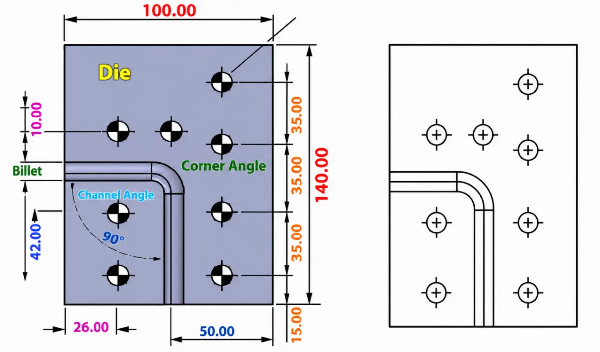
Figure 1. An outline of the ECAP procedure that shows the billet, die, corner angle, and channel angle.
To meet pressing demands across a variety of industries, including automotive, aerospace, defense, medical, and other branches of engineering and science, each industry seeks lightweight, highly durable materials. This blend can be achieved through strong plastic deformation during grain refinement. Because they may undergo significant plastic deformation to give the improved material characteristics required for a range of applications, ultrafine and nanoscale materials have attracted a lot of attention recently. By fine-tuning the grain size by strong plastic deformation, there are several ways to enhance the mechanical characteristics and microstructure. The well-known Hall-Petch relationship [8] shows that specific alloys’ mechanical characteristics can be enhanced by grain refinement. Equation (2) provides the relationship between yield stress and the material’s grain size $$\left(\text{d}\right)$$.
|
```latex{\text{σ}}_{\text{y}}\text{ }\text{=}\text{ }{\text{σ}}_{\text{0}}\text{ }\text{+}\text{ }\text{k}{\text{d}}^{-\frac{\text{1}}{\text{2}}}``` |
(2) |
The terms $$\left({\text{σ}}_{\text{y}}\right)$$ and $$\left(\text{k}\right)$$ in Equation (2) stand for friction stress and yield constant, respectively. As grains become smaller, the material becomes stronger due to this relationship, also known as grain-boundary reinforcement or strengthening [9]. SPD approaches reduce the average grain size by shearing the material very hard in the primary deformation zone. Although the specifics of each SPD method differ, they all aim to achieve the same core goals, which are to reduce grain size and modify mechanical and other qualities. ECAP was shown to be the most successful and efficient severe plastic deformation (SPD) approach for meeting industrial needs after comparing other SPD techniques for grain refinement and microstructure evolution [10]. The Equal Channel Angular Pressing (ECAP) technique involves pushing a billet in the form of a rod through a die and into a channel that bends sharply at an angle. Shear strain is mostly felt at the major deformation zone of the billet as it passes through the point where the two channel sections intersect. High stresses can be produced by repeated pressings without changing the billet’s cross-sectional dimensions. Segal further underlined how important the ECAP technique is for using simple shear to process bulk-structured materials [11]. ECAP uses four primary processing routes, each of which pushes using a distinct sliding mechanism. The microstructures created by ECAP differ significantly as a result of these pathways. After thorough research into the ECAP method, it was discovered that bulk-nanostructured materials undergo significant plastic deformation in the form of equiaxed grains [12].
When it comes to severe plastic deformation (SPD), ECAP is the most effective method of achieving the material’s desired properties. The ECAP process is schematically mentioned in Figure 2, where the material pressing is done with an ECAP die that has a particular corner (20°) and (90°) channel angle. In this process, a plunger in the channel section converge at an angle called the channel angle in the die to help drive the material through the die. The shear strain equation that was first developed using the ECAP approach only took the channel angle into account. But later on, Iwahashi et al. [13] expanded and changed this equation to include the corner angle as well as the channel angle. The homogeneity and equiaxed structure that are produced when the material is processed using ECAP are greatly influenced by the die design parameters. By experimenting with several combinations, the ideal die design parameters were found. Finite element modeling and analysis were also used in some of the assessments. The material’s deformation and strain caused by the ECAP processing were examined using computer models, which resulted in the identification of ideal values for the channel and corner angles. The goal of this optimization was to give the material a homogeneous and uniform microstructure [14].
Additionally, the simulation study found that uniform and homogeneous grain production requires more than one pass. It has also been calculated that a certain amount of friction is required to achieve the intended results [15]. It was shown that strain level and strain distribution homogeneity are increased by raising the friction coefficient, decreasing the die channel angle, or providing back punch pressure in the outlet channel [16]. According to Langdon’s research, materials that are single or polycrystalline can be treated with the ECAP approach. Furthermore, it was noted that of the four possible ways, the route $$\left({\text{B}}_{\text{C}}\right)$$ is the most desirable for generating a homogeneous and equiaxed microstructure [17].
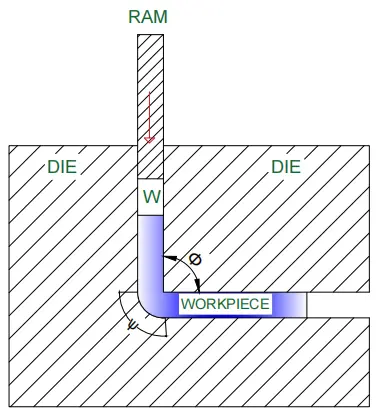
Figure 2. A schematic diagram that shows the material passing through the ECAP die and includes the corner and channel angles.
Processing Al alloy at temperatures as high as 120 °C improves its mechanical properties, according to an experimental investigation done in conjunction with an ECAP simulation. But when processing temperature rises above 120 °C, characteristics decrease. The study also observed a significant decrease in grain size in AA5083 that was treated with ECAP. The findings showed a significant decrease in grain size and distinct grain boundaries. Mechanical strength and hardness showed improvement with an increasing number of passes [18]. With a focus on evaluating the effects of each pass, the study investigated the mechanical and microstructural properties, including impact toughness, tensile strength, and hardness, of a two-phase Al–Mg alloy that was processed using ECAP for up to two passes. The results showed that the casted dendritic microstructure, including casting flaws like micro porosities, was eliminated as a result of the ECAP procedure. Rather, it created a sophisticated microstructure with elongated microconstituents. According to certain research, heat treatment can simultaneously improve strength and cause significant plastic deformation [19]. Additionally, the number of passes in the ECAP processing was investigated in the experimental research in relation to AA5083. Tensile strength and total elongation increased with the number of passes, and these effects were further enhanced by heat treatment [20]. The reduction of grain size and the study of the microstructure’s evolution made it easier to improve the mechanical properties. The results confirm that low-angle grain boundaries were progressively converted into high-angle grain boundaries by the grain subdivision mechanism, resulting in a significant improvement in the grain structure [21]. It is often difficult to deform metallic materials at lower temperatures, and it has also been observed that processing ECAP for materials at lower temperatures is difficult [22]. On annealed magnesium alloy, ECAP processing was carried out to test different processing paths and iterations. It was determined that route C produced superior outcomes versus route A. The results of the literature show that AA5083 has been the subject of substantial research, involving several passes, changes in processing temperature, and approaches that make use of particular die and channel angles. As such, it seems that there is a dearth of experimental work examining the effects of different channel angles and the quantity of passes on AA5083. Therefore, the goal of the current investigation is to comprehend how the number of passes and die angle impact the various mechanical properties of AA5083 [23].
2. Experimental Material and Method
AA5083 is mostly utilized for forming wrought items. The content and chemical makeup of the substance are shown in Table 1. Its composition is 97.70% aluminum, with 0.18% each of silicon and iron coming next. The material was examined for a number of mechanical and physical characteristics, such as its 75 GPa Young’s modulus, 0.38 Poisson’s ratio, 25.8 coefficient of linear expansion at 10−6 (°C)−1, tensile strength range of 50 to 120 MPa, and yield strength range of 25 to 115 MPa [24]. Tool Steel H13, a material extensively used in hot and cold tooling applications due to its high strength and adaptability, is the die material used. Its ability to tolerate heat fatigue is aided by its heated hardness. Tool Steel H13 has great strength and resistance to thermal fatigue, two remarkable qualities that make it a popular choice for hot work applications. It is also used in a variety of cold tooling applications. In terms of performance, H13 outperforms standard steel alloys in terms of wear resistance and hardenability, especially when solidifying large section thicknesses [25]. The mechanical and physical characteristics of Tool Steel H13 are as follows: a Poisson’s ratio between 0.38 and 0.32; tensile strength between 1250 and 1620 MPa; yield strength between 1050 and 1430 MPa; and a density of 7.85 g/cc. The composition percentage information for Tool Steel H13 is shown in Table 2.
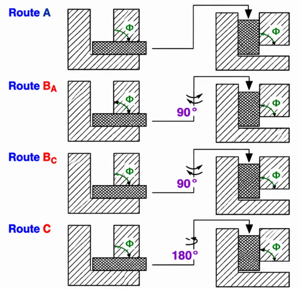
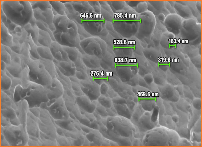
The mechanical properties and microstructure of materials processed with an ECAP die are greatly influenced by the die design parameters [28]. The die design parameters have a major impact on the microstructure and mechanical characteristics of materials treated with the ECAP die. The material experiences its greatest shear strain when the channel angle is (90°) and the corner angle is (20°). However, studies show that the corner angle should be close to (20°) for a more uniform pressing of the material. A die with a channel angle of (90°) and a corner angle of (20°) was thus created after the optimal die design parameters were chosen. The die’s external measurements, which are divided into two parts, are 140 mm × 100 mm × 40 mm. The workpiece is rotated by an angle (90°) in alternate directions between passes in route $$\left({\text{B}}_{\text{A}}\right)$$, while it is pushed without being turned in route A. Route C rotates the workpiece by an angle (180°) in between passes, while Route $$\left({\text{B}}_{\text{C}}\right)$$ rotates the sample by an angle (90°) in the same direction for each pass (clockwise or counterclockwise). The shear path of the billet as it repeatedly travels through intersecting channels distinguishes the various paths. Figure 3 displays the constructed ECAP die with channel angle $$\left(\text{ϕ}\right)$$ and corner angle $$\left(\text{ψ}\right)$$, together with the placement of the processed sample within the ECAP die’s principal deformation zone [29]. Figure 4 makes clear that the size of the grains in the materials as received varies. The material’s average particle size upon receipt is 480 nm. Experimental billet samples were manufactured from this material, which was obtained as a rod with a diameter of 10 mm and a length of about 50 mm. One sample was left unpressed in each of the sample sets, while the remaining samples were pressed once, twice, and three times, respectively, representing 0–2 ECAP passes. After being passed through the die, the finished samples were manufactured with dimensions resembling a circular rod with a diameter of 10 mm and a length of around 50 mm. Figure 5 exhibits the samples that have completed varied numbers of passes through the ECAP die, ranging from 0 to 2 passes utilizing the $$\left({\text{B}}_{\text{C}}\right)$$ method. Figure 5 shows the samples after undergoing tensile fracture inspection on a Universal Testing Machine (UTM).
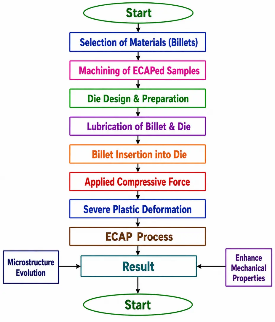
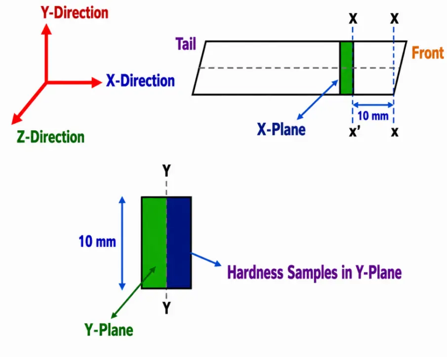
Sample preparation procedure: This chapter describes the methodologies used. Multiple setups are presented in Figure 4, along with a flow chart. The figure summarizes the entire procedure step by step, from receipt of raw material to final results, including the methods, tests, sample preparation, and outcomes. Lubrication conditions during ECAP, Dry Condition: No lubricant; causes high friction and requires higher pressing force. Solid Lubrication: Uses graphite, MoS2, or boron nitride; suitable for high-temperature ECAP and reduces tool wear. Liquid Lubrication: Uses mineral oils, synthetic oils, or grease; commonly used at room temperature to reduce friction and improve surface finish. High-Temperature Lubrication: Uses glass-based or ceramic lubricants; prevents sticking and maintains lubrication at elevated temperatures.
Sever Plastic deformation is a techniques which proved the strength of the materials through the Ultra-fine Grains, UFG means average grain size. These grains are achieved by the Equal Channel Angular pressing method. ECAPed samples are prepared by receiving material in the form of a billet through machining. The dimension was 10 mm in diameter and 50 mm in length. After the ECAP process, samples were cut by the Diamond Cutter at a low feed rate and then cooled. This cutting is performed in a systematic way, as shown in Figure 5.
The image above shows that two types of processes were performed: one at the microstructural level and another on mechanical properties. In both cases samples are prepared by different-different ways. Microstructural analysis was performed using optical microscopy to observe the evolution of grain structure, and optical samples were prepared through different stages; the final-stage sample surface appeared as a mirror image. Mechanical properties find out through the tensile testing and Hardness testing, tensile testing was performed through the computer based tensile machines. And tensile samples were prepared according to ASTM Standard (American Society for Testing and Materials).
3. Finite Element Analysis for Die Design
3.1. Simulation Procedure for Die Design
Using the commercial program Ansys Workbench 15.0 and the Finite Element Method (FEM), the ECAP approach was assessed. When building the model, a plane strain condition was taken into account. The die and the ram as hard, analytical bodies. Low pressing speeds are found to satisfy the isothermal requirement, as indicated by both theoretical and experimental data. In the software simulations, the aluminum alloy AA5083 was used as the billet material and was assumed to exhibit elastic-plastic behavior [30]. Convergence to a stable solution is a primary issue in this kind of computer research, mainly because of solid nonlinearities caused by friction, deformations, and contact. In order to minimize computation time and prevent mesh failure during the analysis of large deformations, mass scaling was used in the simulations (Table 3).
Table 3. Simulation parameters.
|
Parameter |
Billet Length (mm) |
Billet Diameter (mm) |
Die Breadth (mm) |
Die Length (mm) |
Die Height (mm) |
Punch Speed (mm/s) |
Time Increment (s) |
Temperature (°C) |
Friction Factor |
Die Channel Angle |
Corner Angle |
|---|---|---|---|---|---|---|---|---|---|---|---|
|
Value |
50 |
10 |
100 |
140 |
40 |
1.2 |
0.3 |
25 |
0.28 |
90°, and 120° |
20° |
3.2. Modeling of Die and Ram
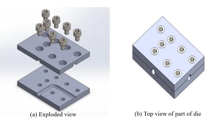
Using exact measurements and computations, SOLIDWORKs software version 2017 was used to create and model the die, billet, plunger, or ram. All measurements were constantly kept in millimeters. The die is designed in two parts in SOLIDWORKS software: the upper die and the bottom die. After that, these components are put together to form a complete die with the right channel for passing the sample or billet through [31]. Two cylindrical pins and six Allen screws are used to join the die’s upper and lower sections. The cylindrical pins are 8 mm in diameter, and the Allen screws are 25 mm in diameter. Tool Steel H13 is the material used for the die, and some parameters are indicated by the $$\left({\text{ϕ}\text{ }\text{=}\text{ }\text{90}}°\right)$$ and $$\left({\text{ϕ}\text{ }\text{=}\text{ }\text{120}}°\right)$$. It is expected that the die’s $$\left(\text{ψ}\right)$$ value is equal to (20°). The output channel measured 140 mm in length, while the inlet channel measured 60 mm. When the billet was designed, its measurements were 50 mm in length and 10 mm in diameter [32]. As shown in Figure 6, AA5083 material was used for the passing sample, and to make the billet, and Tool steel H13 was selected to build the die. Table 4 represents the processing parameters of Meshing for Material.
Table 4. Processing parameters of Meshing for Material, Properties, Statistics.
|
Material |
||
|---|---|---|
|
Assignment |
AA5083 |
H 13 Steel |
|
Bounding Box |
||
|
Length of X-Axes |
2.5 cm |
22.5 cm |
|
Length of Y-Axes |
2.5 cm |
5.5 cm |
|
Length of Z-Axes |
8.5 cm |
16.5 cm |
|
Properties |
||
|
Volume |
27.144 cm3 |
0.0018282 × 108 cm3 |
|
Mass |
6.8788 × 10⁻² kg |
14.389 kg |
|
Centroid of X-Axes |
0.3732 cm |
4.228 cm |
|
Centroid of Y-Axes |
16.557 cm |
13.219 cm |
|
Centroid of Z-Axes |
30.252 cm |
17.835 cm |
|
1st Moment of Inertia |
0.38787 kg·cm2 |
315.70 kg·cm2 |
|
2nd Moment of Inertia |
0.38787 kg·cm2 |
834.19 kg·cm2 |
|
3rd Moment of Inertia |
0.034576 kg·cm2 |
571.79 kg·cm2 |
|
Statistics |
||
|
Nodes |
6314 |
38,768 |
|
Elements |
1306 |
22,881 |
|
Mesh Metric |
None |
|
3.3. Meshing Method
In order to speed up the simulation process, the model is divided into many smaller components in a crucial phase called meshing in computer-aided engineering simulations. To provide precise and error-free results, the simulation is run separately on each of these smaller components. The method affects the solution’s accuracy, convergence, and speed [33]. Furthermore, the time needed to build and mesh the model frequently makes up a sizable chunk of the total time required to get results from a CAE solution. Depending on the structure that has to be meshing, Ansys Workbench gives users the freedom to select from a variety of meshing options, such as sweep meshing or automatic meshing. Ansys Workbench’s meshing technologies allow users to precisely place the right mesh in the right places once the ideal model has been determined. This ensures that the simulation accurately validates the model. The default setting for the particle sizes was coarse, although they were thought to be fine [34]. An automatic meshing technique was used for the die and all other equipment used in the analysis. The relevance center and span angle center were set to fine, and the element sizes in the meshing process varied from 2 to 5 mm.
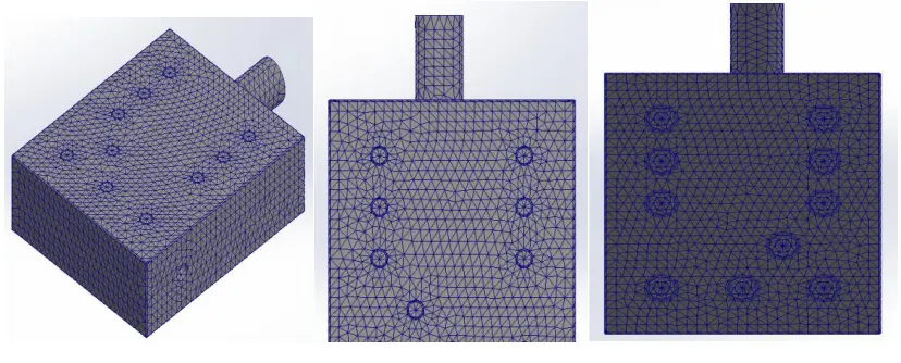
The tool steel used to make the die was H-13, which has a carbon content of about 0.8%. Figure 6a shows the ECAP die schematic in an exploded form, and Figure 6b shows the die assembly. Figure 6c which supports the length of the sample, are both made of H-13 tool steel, the same material used to produce the die.
 |
||
|
(a) |
(b) |
(c) |
Figure 6. Meshed parts of the die with a different view. (a) Meshed part view one, (b) Meshed part view two, (c) Meshed part view three.
After the mesh has been created, the die has been separated into 23,881 elements and the billet into 1306 elements. For the die with a channel angle of $${\text{ϕ}}$$, this particular element count was calculated using an element size of 4 mm. Without changing the overall number of parts, it seems that this amount is adequate for utilizing Ansys Workbench to estimate the workpiece’s deformation and strain rate [35]. Table 2 indicates that the meshed die and a cross-sectional view displaying the internal meshed section of the die are depicted in Figure 7a,b.
3.4. Strain Imposed of ECAP Technique
The material undergoes an abrupt shear strain each time it passes through an ECAP die [36]. The strain levels can be computed using a theoretical model based on numerous die designs. The channel angle in this computation is denoted by $$\left(\text{ϕ}\right)$$ and the corner angle, denoted by $$\left(\text{ψ}\right)$$ is related to the matching arc of curvature at the channel intersection. The following limiting instances can be explored for this analysis: (a) $$\left(\text{ψ}\text{ }\text{=}\text{ 0°}\right)$$, (b) $$\left(\text{ψ}\text{ }\text{=}\text{ }\text{π}\text{ }-\text{ }\text{ϕ}\right)$$, and (c) $$\left(\text{ψ}\right)$$ lies between $$\left(\text{ψ}\text{ }\text{=}\text{ 0°}\right)$$ and $$\left(\text{ψ}\text{ }\text{=}\text{ }\text{π}\text{ }-\text{ }\text{ϕ}\right)$$. Since it is anticipated that the dies will be manufactured accurately and the component will be properly lubricated, frictional losses can be ignored in the aforementioned situations [37].
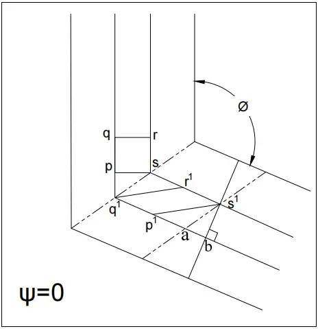
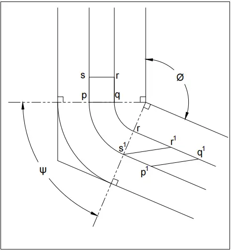
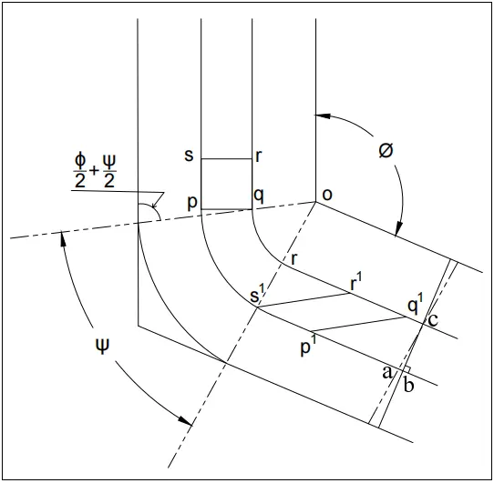
Here, for analytical purposes, shear at the junction of the two channels deforms a little square piece with measurements $$\left(\text{p}\right)$$, $$\left(\text{q}\right)$$, $$\left(\text{r}\right)$$, and $$\left(\text{s}\right)$$ into the shape given by $$\left({\text{p}}^{\text{1}}\right)$$, $$\left({\text{q}}^{\text{1}}\right)$$, $$\left({\text{r}}^{\text{1}}\right)$$, $$\left({\text{s}}^{\text{1}}\right)$$, Case (a) $$\left(\text{ψ}\text{ }\text{=}\text{ 0°}\right)$$, Shear tension on the workpiece $$\left(\text{γ}\right)$$ is given by $$\left(\text{γ}\text{ }\text{=}\text{ }{\text{p}}^{\text{1}}\text{b}/\text{b}{\text{s}}^{\text{1}}\right)$$ where $$\left({\text{qd}}^{\text{1}}\text{ }\text{=}\text{ }\text{ad}\right)$$ and by geometry $$\left(\text{ab}\text{ }\text{=}\text{ }\text{b}{\text{s}}^{\text{1}}\text{cot}\left(\text{ϕ}/\text{2}\right)\right)\text{, }$$so
|
```latex\text{p}{\text{q}}^{\text{1}}\text{ }\text{=}\text{ }\text{s}{\text{r}}^{\text{1}}\text{ }\text{=}\text{ }{\text{p}}^{\text{1}}\text{a}\text{ }\text{=}\text{ }\text{ab}\text{ }\text{=}\text{ }\text{pscot}\left(\text{ϕ}/\text{2}\right)``` |
(3) |
and as $$\left({\text{p}}^{\text{1}}\text{b}\text{ }\text{=}\text{ }{\text{p}}^{\text{1}}\text{a}\text{ }\text{+}\text{ }\text{ab}\right)$$.
Therefore $${\text{p}}^{\text{1}}\text{b}\text{ }\text{=}\text{ }\text{pscot}\left(\text{ϕ}/\text{2}\right)$$
If $$\left(\text{ψ}\text{ }\text{=}\text{ 0°}\right)$$, then shear strain $$\left(\text{γ}\right)$$ will be (Figure 6a) [38].
|
```latex\left(\text{γ}\text{ }\text{=}\text{ }\text{2cot}\left(\frac{\text{ϕ}}{\text{2}}\right)\right)``` |
Case (b) $$\left(\text{ψ}\text{ }\text{=}\text{ }\text{π}\text{ }-\text{ }\text{ϕ}\right)$$, for this case, shear strain $$\left(\text{γ}\right)$$ is given by
|
```latex\left(\text{γ}\text{ }\text{=}\text{ }\text{r}{\text{r}}^{\text{1}}/\text{r}{\text{q}}^{\text{1}}\right)``` |
|
|
```latex\left\{{\text{rq}}^{\text{1}}\text{ }\text{=}\text{ }\text{sp}\text{ }\text{=}\text{ }\left(\text{op}\text{ }-\text{ }\text{os}\right)\right\}``` |
And
|
```latex\left\{{\text{pq}}^{\text{1}}\text{ }\text{=}\text{ }\text{s}{\text{r}}^{\text{1}}\text{ }\text{=}\text{ }\text{opψ}\text{ }\text{=}\text{ }\left({\text{rr}}^{\text{1}}\text{ }\text{=}\text{ }\text{osψ}\right)\right\}``` |
(4) |
So $$\left\{{\text{rr}}^{\text{1}}\text{ }\text{=}\text{ }\left(\text{op}\text{ }-\text{ }\text{os}\right)\text{ψ}\right\}$$
When $$\left(\text{ψ}\text{ }\text{=}\text{ }\text{π}\text{ }-\text{ }\text{ϕ}\right)$$, then shear strain $$\left(\text{γ}\right)$$ will be (Figure 6b) $$\left(\text{γ}\text{ }\text{=}\text{ }\text{ψ}\right)$$ [39].
In this case (c) $$\left(\text{ψ}\right)$$ lie between $$\left(\text{ψ}\text{ }\text{=}\text{ 0°}\right)$$ and $$\left(\text{ψ}\text{ }\text{=}\text{ }\text{π}\text{ }-\text{ }\text{ϕ}\right)$$, so for this case, shear strain $$\left(\text{γ}\right)$$ will be given by $$\left(\text{γ}\text{ }\text{=}\text{ }{\text{p}}^{\text{1}}\text{u}/{\text{s}}^{\text{1}}\text{u}\right)$$ where $$\left({\text{s}}^{\text{1}}\text{u}\text{ }\text{=}\text{ }\text{ps}\right)$$ and from the geometry $$\left\{{\text{p}}^{\text{1}}\text{u}\text{ }\text{=}\text{ }\left({\text{p}}^{\text{1}}\text{t}\text{ }\text{+}\text{ }\text{tu}\right)\text{ }\text{=}\text{ }\left(\text{r}{\text{r}}^{\text{1}}\text{ }\text{+}\text{ }\text{pc}\right)\right\}\text{, }\left\{\text{pc}\text{ }\text{=}\text{ }\text{pscot}\left(\text{ϕ}/\text{2}\text{+}\text{ψ}/\text{2}\right)\right\}$$
here $$\left\{{\text{pq}}^{\text{1}}\text{ }\text{=}\text{ }\text{s}{\text{r}}^{\text{1}}\text{ }\text{=}\text{ }\left(\text{pc}\text{ }\text{+}\text{ }\text{ocψ}\right)\text{ }\text{=}\text{ }\left(\text{r}{\text{r}}^{\text{1}}\text{ }\text{+}\text{ }\text{osψ}\right)\right\}$$
$$\left\{\left(\text{oc}\text{ }-\text{ }\text{os}\right)\text{ }\text{=}\text{ }\text{pscosec}\left(\text{ϕ}/\text{2}\,\text{+}\,\text{ψ}/\text{2}\right)\right\}$$.
And now $$\left(\text{r}{\text{r}}^{\text{1}}\right)$$ is given by $$\left\{\text{r}{\text{r}}^{\text{1}}\text{ }\text{=}\text{ }\text{pc}\text{ }\text{+}\text{ }\text{pscosec}\left(\text{ϕ}/\text{2}\text{+}\text{ψ}/\text{2}\right)\right\}$$
Therefore
|
```latex\left\{{\text{p}}^{\text{1}}\text{b}\text{ }\text{=}\text{ }\text{2ps}\text{cot}\left(\text{ϕ}/\text{2}\text{+}\text{ψ}/\text{2}\right)\text{ }\text{+}\text{ }\text{psψcosec}\left(\text{ϕ}/\text{2}\text{+}\text{ψ}/\text{2}\right)\right\}``` |
(5) |
So shear strain $$\left\{\text{γ}\right\}$$ is given by
|
```latex\left\{\text{γ}\text{ }\text{=}\text{ }\text{2cot}\left(\text{ϕ}/\text{2}\text{+}\text{ψ}/\text{2}\right)\text{ }\text{+}\text{ }\text{ψcosec}\left(\text{ϕ}/\text{2}\text{+}\text{ψ}/\text{2}\right)\right\}``` |
(6) |
Now the equivalent strain $$\left({\text{ε}}_{\text{N}}\right)$$ is given by
|
```latex{\text{ε}}_{\text{N}}\text{ }\text{=}\text{ }{\left\{\frac{\text{2}\left[{\text{ε}}_{\text{x}}^{\text{2}}\text{ }\text{+}\text{ }{\text{ε}}_{\text{y}}^{\text{2}}\text{ }\text{+}{\text{ }\text{ε}}_{\text{z}}^{\text{2}}\text{ }\text{+}\text{ }\frac{{\text{γ}}_{\text{xy}}^{\text{2}}\text{ }\text{+}\text{ }{\text{γ}}_{\text{yz}}^{\text{2}}\text{ }\text{+}\text{ }{\text{γ}}_{\text{zx}}^{\text{2}}}{\text{2}}\right]}{\text{3}}\right\}}^{\frac{\text{1}}{\text{2}}}``` |
(7) |
|
```latex{\text{ε}}_{\text{N}}\text{ }\text{=}\text{ }\text{N}\left[\frac{\text{2cot}\left(\frac{\text{ϕ}}{\text{2}}\text{ }\text{+}\text{ }\frac{\text{ψ}}{\text{2}}\right)\text{ }\text{+}\text{ }\text{ψcosec}\left(\frac{\text{ϕ}}{\text{2}}\text{ }\text{+}\text{ }\frac{\text{ψ}}{\text{2}}\right)}{\text{3}}\right]``` |
(8) |
3.5. Impact of Coefficient of Friction
The homogeneity of the microstructure and the loading rate are highly dependent on the friction between the sample and the workpiece. According to F. Djavanroodi’s research, a high coefficient of friction can remove the corner gap that forms at the intersection of the channels. But there’s another benefit to this strategy: a faster loading rate [41]. After examining the impacts of friction, Atul Dayal concluded that friction significantly affects softer materials but has little effect on the homogeneity of hard materials. Higher friction produces a more uniform structure in softer materials.
4. Experimental Results and Discussions
The main focus of this research is the effects of parameters like $$\left(\text{ϕ}\right)$$, $$\left(\text{ψ}\right)$$, $$\left(\text{μ}\right)$$, $$\left(\text{ε}\right)$$, punch load. Using analytical observations, graphs, and comparisons of the analytical results, we will evaluate and contrast each of these parameters. Phase-by-phase results are evaluated at two distinct channel angles $$\left(90°\right)$$ and $$\left(120°\right)$$, where the corner angle is equal to $$\left(0°\right)$$. The outcomes will be examined for the two frictional situations, i.e., for $$\left(\text{μ}\text{ }\text{=}\text{ 0}\right)$$ and $$\left(\text{μ}\text{ }\text{=}\text{ }\text{0.28}\right)$$. The distorted geometry can distinguish the two different loading phases of the ECAP process. The findings show that different $$\left(\text{ϕ}\right)$$ values correspond to varied ram displacement during the deformation stages. The leading edge of the workpiece experiences considerable distortion in the major deformation zone during the first stage of workpiece development. The majority of the deformation happens here [42]. Phase I is represented by the deformation of the geometry for $$\left(\text{ϕ}\text{ }\text{=}\text{ 90°}\right)$$ with a displacement of 12 mm. Both the volume of workpiece deformation and internal tensions noticeably increase during Stage I. At this point, the applied force also increases proportionately, which is explained by the first deformation of the initially undisturbed workpiece. After Stage I, the workpiece’s top portion reaches the Main Deformation Zone (MDZ) after the loading point during Stage II. The workpiece’s rear section experiences the most plastic deformation in Stage I and is discharged past the peak point until the distortion stabilizes. This leads to a decrease in the load during Stage II. The findings showed that, for a given value of $$\left(\text{ϕ}\text{ }\text{=}\text{ 90°}\right)$$, phase II does not occur [43]. When contact is achieved between the workpiece and the die’s channel, Stage III gets started. The strain on the die in the first stage is comparatively less for a large die because of the less important rounded interior corner angle. On the other hand, for stages II and III, the burden rises as $$\left(\text{ϕ}\right)$$ rises, which is explained by the variability in big $$\left(\text{ψ}\right)$$ cases. The observation revealed that the load overshoot is a recurrent load brought on by strain concentration at the back of the workpiece segment rather than being indicative of the entire workpiece.
4.1. Impact of Channel Angle and Friction
In the frictionless case, the effective strain in the workpiece after it goes through the die is equal to $$\left(\text{ϕ}\right)$$, $$\left(\text{ϕ}\text{ }\text{=}\text{ 90°}\right)$$, and $$\left(\text{ϕ}\text{ }\text{=}\text{ 120°}\right)$$. The figure and graph show the distribution of strain across the cross-section that was taken at the midpoint of the workpiece. It illustrates how strain is applied consistently throughout the ECAP process at a certain point. This point-to-point strain distribution can be averaged to provide the mean value of the strain imparted to the workpiece during the ECAP process [44]. Two curves corresponding to the corner and channel angles can be seen during the simulation. The result of billet twisting during deformation is frequently these angles. At the die corner, the expansions in $$\left(\text{ϕ}\right)$$ and $$\left(\text{ψ}\right)$$ were joined under frictionless conditions. The higher resistance to frictional forces at the billet surface is responsible for the elimination of the corner hole when friction is considered. The drag acts as a rear weight, drawing material through the die. The non-uniform closures of the billet at $$\left(\text{ϕ}\right)$$ bigger than $$\left(\text{ϕ}\text{ }\text{=}\text{ 90°}\right)$$ are slightly altered by friction. As predicted by the experimental results, the data below show that the case of $$\left(\text{ϕ}\text{ }\text{=}\text{ 90°}\right)$$ experienced the most strain and deformation, whereas the case of $$\left(\text{ϕ}\text{ }\text{=}\text{ 120°}\right)$$ experienced the smallest strain and distortion [45]. The strain is highest on the curve and is larger when $$\left(\text{ϕ}\right)$$ is equal to $$\left(90°\right)$$ than $$\left(120°\right)$$, according to the graphs in Figure 7a,b. The total deformation and corresponding elastic strain for different channel angles (90°, 120°) are displayed in the data below, along with graphs that illustrate how the strain changes over time.
4.2. Impact of Punch Load
The change in load estimation with $$\left(\text{ψ}\right)$$, $$\left(\text{ϕ}\right)$$ and $$\left(\text{μ}\right)$$ was looked at in this section of the results. The necessary load to expel the billet under frictionless and frictional ($$\text{μ}\text{ }\text{=}\text{ }\text{0.28}$$) circumstances for different channel angles, $$\left(90°\right)$$ and $$\left(120°\right)$$ with a corner angle of $$\left(20°\right)$$. As the workpiece travels, the punch pressure is increased until the workpiece experiences shear strain. From the point of maximum strain or load, the applied force gradually reduces and continues at a very slow rate until the procedure is completed [46]. Because the material may flow freely along the die path, increasing the channel angle reduces the required load to punch the billet in both friction and frictionless situations. In the frictional situation, the results show that the applied load increases dramatically for several passes as the frictional coefficient increases ($$\text{μ}\text{ }\text{=}\text{ }\text{0}$$ to $$\text{μ}\text{ }\text{=}\text{ }\text{0.28}$$). This happens as a result of frictional resistance acting against the direction of motion of the surface. To reduce the applied load and increase the die’s lifespan, it is preferable to avoid using a high coefficient of friction during the ECAP process [47]. At a certain position, the greatest punch burden needed to produce a 36.3 kN. On the other hand, a channel angle equal to $$\left(90°\right)$$ and punch loads of 28.6 kN and 15.8 kN are needed for channel angles $$\left(104.5°\right)$$ and $$\left(\text{119.6°}\right)$$, respectively. Because the applied loads in the two situations were of different magnitudes, the results of the frictionless example showed that the workpiece was under distinct strains. Less angles mean a larger necessary load, which raises the magnitude of the strain and causes more deformation.
4.3. Impact of ECAP Pressing on Stress–Strain Behaviour
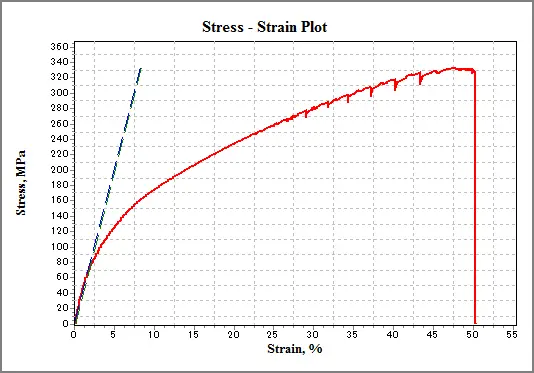
The Universal Testing Machine (TUF-C-1000) S.M. Engineer, Pune, Maharashtra was used in the lab to create and test samples of different sorts (without a pass, one pass, and two passes) using Equal Channel Angular Pressing material processing. The sample’s dimensions are roughly 10 mm in diameter and 78.53 mm2 in cross-section. It has a 25 mm gauge length at first [48]. Figure 7 SEM micrograph of as-received materials for samples with 0–2 ECAP processing runs. According to the graph, the first part of the curve in the material as received exhibits a nearly linear relationship, culminating at roughly 263 MPa of stress and 0.0082 of strain. After the first pass, the corresponding values were 313 MPa and 0.0087; after the second pass, the values were 341 MPa and 0.0064. Following the third pass, the readings climbed somewhat to 352 MPa and 0.0061, respectively. The material’s reduced grain size in each ECAP-processed sample may be the cause of the increase in tensile strength that was seen. Furthermore, the decrease in particle size may also be responsible for the decrease in elongation following each ECAP processing [49]. If the reduction in grain size results in decreased elongation and increased tensile strength, then the deformed material complies with the Hall-Patch equation. A similar pattern of improved tensile strength and decreased elongation has also been documented in several experiments on AA5083 treated with ECAP [50].
4.4. Impact of ECAP Pressing on Tensile Strength
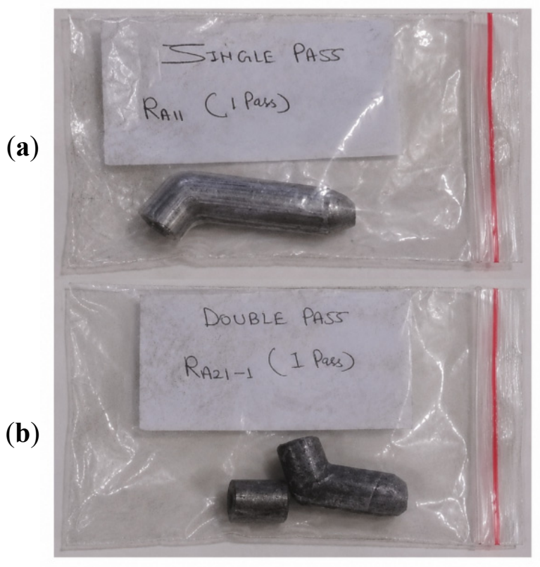
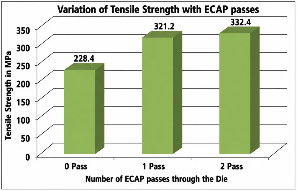
The material’s essential tensile strength was assessed using the TUF-C-1000 model Universal Testing Machine in compliance with IS: 1608–2005 (RA 2017)/IS 1586–1:2018 methodology. A treated rod that was around 10 mm in diameter and 50 mm long was used to create the specimens. The specimens measured 50 mm in gauge length and 10 mm in diameter [51]. One sample was made with one pass, another with two passes, and a third with no passes at all. Figure 8 single pass and double pass ECAP processing specimen via ECAP. Tensile strength increased dramatically from 228.4 to 332.4 MPa after the first pass, which was explained by the material’s grain consolidation and considerable shear strain. Due mostly to the continuous grain refinement, there was a slight increase to 356.2 MPa following the second run and a slight increase to 321.2 MPa following the third pass. The trends detected in the results were similar to those seen in previous research [52]. Experiments were conducted to validate these results, and the results showed that AA5083’s tensile strength increased significantly after four (90°) channel die passes, from 196 to 360 MPa.
 |
 |
 |
|
(a) |
(b) |
(c) |
Figure 8. (a) Case (a) when $$\left(\text{ψ}\text{ }\text{=}\text{ 0°}\right)$$. (b) Case (b) when $$\left(\text{ψ}\text{ }\text{=}\text{ }\text{π}\text{ }-\text{ }\text{ϕ}\right)$$. (c) Case (c) when $$\left(\text{ψ}\right)$$ lie between $$\left(\text{ψ}\text{ }\text{=}\text{ 0°}\right)$$ and $$\left(\text{ψ}\text{ }\text{=}\text{ }\text{π}\text{ }-\text{ }\text{ϕ}\right)$$.
4.5. Impact of ECAP Passes on 0.3% Proof Stress
Appearance of actual specimens; (a) Specimen before tensile test, and (b) Specimen after tensile test shown in Figure 9. The trend in the material’s tensile strength is largely reflected in this graph. For the 0.3% proof stress, similar trends were observed in the experimental material. In the same location, the 0.3% proof stress increased dramatically from 268.4 to 349.2 MPa after only one ECAP pass [53]. Due to further grain consolidation and refinement, there was a minor increase to 347.2 MPa after two ECAP runs, and a significant increase to 349.2 MPa after three ECAP passes, as shown in Figure 10. These results show a similar trend and are consistent with earlier research findings [54].
4.6. ECAP with an Impact on Elongation and Ductility
Figure 11 shows the relation between stress and strain curve for tensile test. Ductility was observed to have drastically decreased from 16.20 to 14.20 after only one ECAP pass [55]. Grain processing in the die’s main deformation zone, which causes material consolidation and the removal of empty space, is responsible for the reduction shown in Figure 12. After the second ECAP pass, ductility was further shown to decline progressively with each pass, reaching a minimum value of 12.40 after the third pass. Previous research indicates that after four or more passes, ductility either remains unchanged or significantly decreases. The elongation percentage decrease was corroborated by earlier research using AA5083 samples, which showed a 34% decrease in elongation after two runs of ECAP with channel angle. These outcomes strongly concur with those of earlier studies [56].
4.7. Grain Size Effects of ECAP Passes
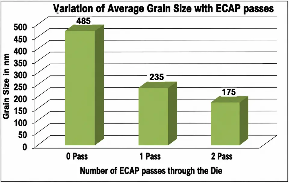
After adjusting the number of ECAP passes, the trend in the treated AA5083 material’s average grain size is displayed in Figure 13. Several test samples were created, and micrographs were analyzed at room temperature 28 °C in order to ascertain the average grain size [57]. As-received material was used to prepare one sample, which underwent no pass processing; one and two passes were applied to the remaining samples, respectively. Based on the optical microstructure, the average grain size was determined using the line intercept method. It is clear from Figure 13 that following the initial two ECAP processing rounds, the grain size dramatically shrank. After two passes, the grain size decreased to about 175 nm from its initial measurement of 485 nm without any passes or zero passes [58]. The material in the primary deformation zone is subjected to severe shear strain, which is responsible for the reduction in grain size. During the first pass of ECAP, this strain significantly reduces the average grain size; subsequent passes provide a relatively lower reduction. With each subsequent pass, more power is needed to reduce the average grain size even further, as mentioned in Figure 14. Grain size decreases as a result of passing the material via the channel angle of 90°, according to experimental verification. After four passes, the data showed a significant decrease of up to 235 nm, which amply validates our experimental findings [59].
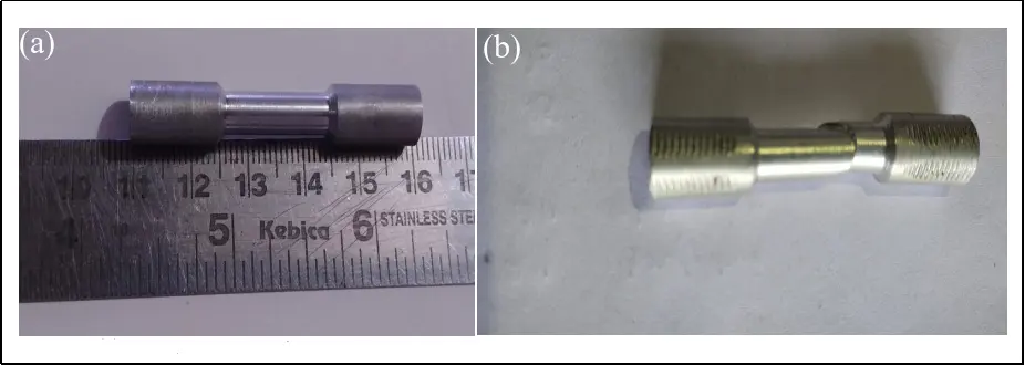
Figure 13. Appearance of actual specimens: (a) Specimen before tensile test, and (b) Specimen after tensile test.
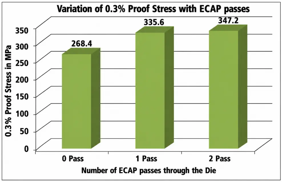
Figure 14. A comparative graph that displays the variation in proof stress following each ECAP pass.
4.8. Impact of ECAP Passes on Hardness
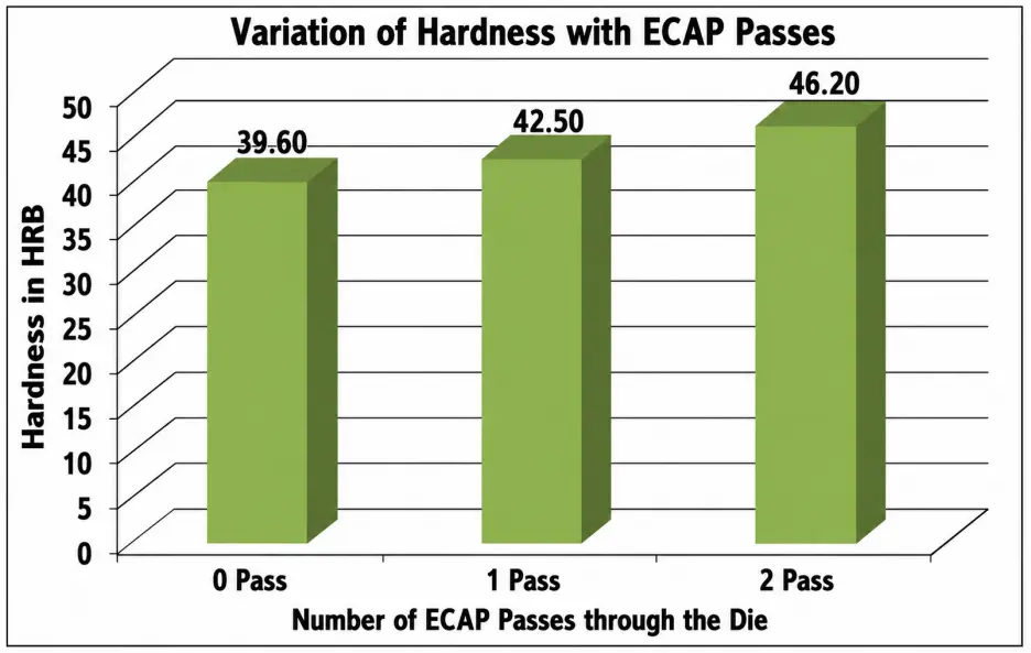
The tested ECAP treated material, AA5083, was measured for hardness using a hardness testing machine at a room temperature of approximately 27 °C. The hardness findings of the sample processed with the ECAP die are shown in Figure 12. The HRB representation of the hardness value rose with each successive ECAP pass [60]. After one pass, there is a noticeable rise in hardness, there is still an increase, but the increments in hardness values are a little bit lower. The difficulty of combining the grains with each pass, which results in more consolidation of the grains with each subsequent pass, may be the cause of the variance in hardness in Figure 15. After two passes, the numerical hardness value rose from 39.60 HRB without any passes to 46.20 HRB. After two passes, the hardness of AA5083 increased from 48 BHN to 70 BHN based on similar patterns that were seen. This attests to a regular pattern in the material’s enhanced hardness after several cycles through ECAP [61] (Figure 16 and Figure 17).
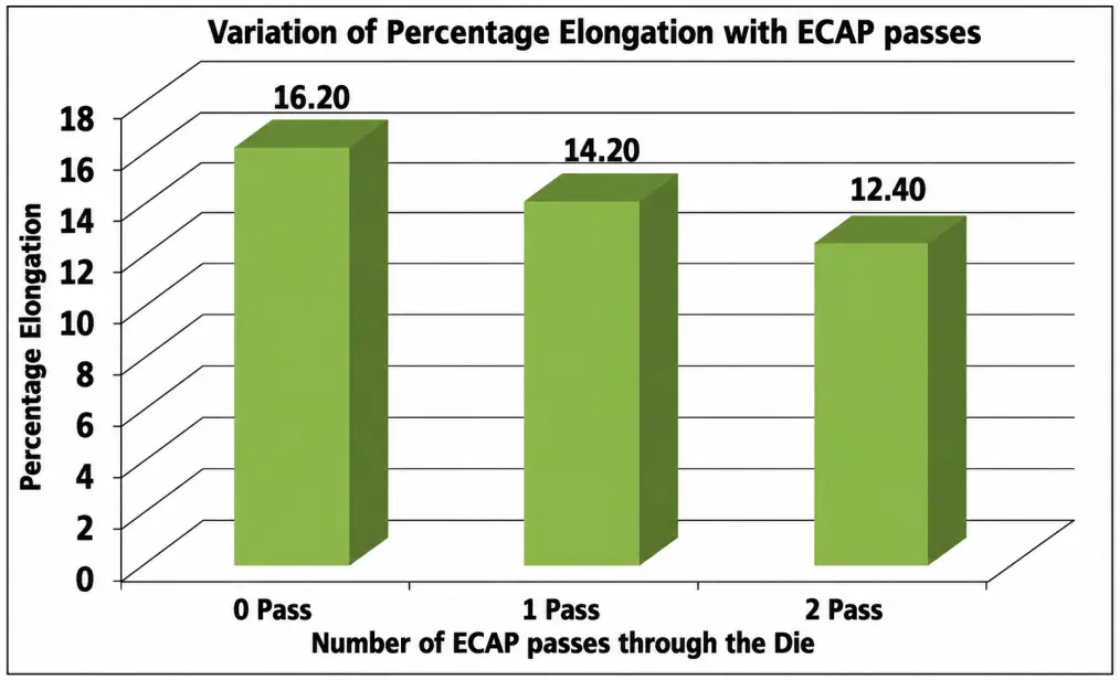
Figure 15. A comparative graph demonstrating the variance in elongation (ductility) following each ECAP pass.
5. Conclusions
The effect of deformation and strain on the material under both frictional and frictionless conditions as it goes through a die with different channel angles. Using a ram, the punch load is applied to the AA5083 material workpiece, enabling it to pass through the Tool Steel H13 die, which is substantially stronger than AA5083. Within the die’s dimensional constraints, strain and deformation in the material were computed for (90°) and (20°) channel angles, as well as a corner angle equal to (20°), taking into account both friction and frictionless conditions. Out of all the angles, the combination of the corner angle (20°) and channel angle (90°) produces better outcomes than any other angle. As the channel angle reduces, the billet becomes more homogeneous. A die channel angle that is not quite (90°) has resulted in a more even distribution of strain. The corner angle has little bearing on the distribution of strain, but it is essential to close the corner gap and make sure that material flows smoothly through the main deformation zone. The corresponding plastic strain and deformation are directly influenced by variations in the corner and channel angles. The material flows through the die more smoothly as the channel angle increases. Applying friction to the path causes the applied punch load to increase as well. The assumptions in the analytical model account for the discrepancy between analytical and numerical data. After the system was run through zero to two times, more conclusions were drawn. After two ECAP runs, the tensile strength increased dramatically from 225.8 to 358.4 MPa. The stress-strain graph demonstrates that even while the elongation slightly drops with each pass, the tensile strength increases. The elongation was 16.20 prior to any passes, and it was 12.40 after the third run through the ECAP die. The UFG structure’s homogenous and equiaxed grains complied with ASTM rule 8–9. In addition, after zero to two passes, the average particle size dropped from 480 to 170 nm. Concurrently, the number of ECAP passes increased from 0 to 2, and the hardness increased from 39.60 to 46.20 HRB.
Author Contributions
All authors were involved in writing the original draft, reviewing and editing the manuscript. All authors have read and agreed to the published version of the manuscript.
Ethics Statement
Not applicable.
Informed Consent Statement
Not applicable.
Data Availability Statement
The datasets used and/or analysed during the current study available from the corresponding author on reasonable request.
Funding
This research received no external funding.
Declaration of Competing Interest
The authors declare that they have no known competing financial interests or personal relationships that could have appeared to influence the work reported in this paper.
References
- Valiev RZ. Structure and mechanical properties of ultrafine-grained metals. Mater. Sci. Eng. A 1997, 234–236, 59–66. DOI:10.1016/S0921-5093(97)00183-4 [Google Scholar]
- Segal VM. Materials processing by simple shear. Mater. Sci. Eng. A 1995, 197, 157–164. DOI: 10.1016/0921-5093(95)09705-8 [Google Scholar]
- Nagasekhar AV, Tick-Hon Y, Li S, Seow HP. Effect of acute tool-angles on equal channel angular extrusion/pressing. Mater. Sci. Eng. A 2005, 410–411, 269–272. DOI:10.1016/j.msea.2005.08.043 [Google Scholar]
- Singh N, Agrawal MK, JiaoJiao W, Elumalai P, Prabhakar S. Influence of Back Pressure on the Microstructure and Texture Characteristics of AA5083 During Equal Channel Angular Pressing Under Thermal Effect. Eng. Rep. 2026, 8, e70755. DOI:10.1002/eng2.70755 [Google Scholar]
- Iwahashi Y, Wang J, Horita Z, Nemoto M, Langdon TG. Principle of equal-channel angular pressing for the processing of ultra-fine grained materials. Scr. Mater. 1996, 35, 143–146. DOI:10.1016/1359-6462(96)00107-8 [Google Scholar]
- Zhang X, Han J, Tian J, Zhu L, Zhang P, Wang Y, et al. The Effects of Pass Number and Die Channel Angle of Equal Channel Angular Pressing on Innovative Magnesium Composite Material. Metals 2025, 15, 349. DOI:10.3390/met15040349 [Google Scholar]
- Rymer LM, Höppel HW, Ortner P, Pfeffer N, Stark A, Winter L, et al. Hardening by annealing in the medium-entropy alloy CrCoNi after equal-channel angular pressing. Mater. Today Commun. 2026, 51, 114751. DOI:10.1016/j.mtcomm.2026.114751 [Google Scholar]
- Beytüt H, Özbeyaz K, Temiz Ş. A Novel Hybrid Die Design for Enhanced Grain Refinement: Vortex Extrusion–Equal-Channel Angular Pressing (Vo-CAP). Appl. Sci. 2025, 15, 359. DOI:10.3390/app15010359 [Google Scholar]
- Balali M. Investigation of Effective Parameters in Elliptical Spiral Equal-Channel Angular Extrusion Utilizing the Taguchi Process for Optimal Design. AUT J. Mech. Eng. 2026, 10, 337–352. DOI:10.22060/ajme.2026.25026.6243 [Google Scholar]
- Ebrahimi R, Reihanian M, Botkin A, Valiev RZ. Development of Equal Channel Angular Pressing in Parallel Channels Toward Enhanced Efficiency. Iran. J. Sci. Technol. Trans. Mech. Eng. 2025, 49, 1599–1618. DOI: 10.1007/s40997-025-00863-5 [Google Scholar]
- Atif M, Liu H, Zhou J, Chen Y, Qin X, Khan ZU, et al. Influence of rolling and equal channel angular pressing (ECAP) on the microstructural evolution and mechanical properties of Zn-0.5Li-0.3Mn alloy. Mater. Sci. Eng. A 2026, 953, 149757. DOI:10.1016/j.msea.2026.149757 [Google Scholar]
- Wongsa-Ngam J, Noraphaipaksa N, Kanchanomi C, Langdon TG. A study of die parameters influencing the plastic deformation for 3D finite element simulations of equal-channel angular pressing. J. Mater. Sci. 2025, 60, 14207–14220. DOI:10.1007/s10853-025-11249-y [Google Scholar]
- Iwahashi Y, Furukawa M, Horita Z, Nemoto M, Langdon TG. Microstructural characteristics of ultrafine-grained aluminum produced using equal-channel angular pressing. Met. Mater. Trans. A 1998, 29, 2245–2252. DOI:10.1007/s11661-998-0102-5 [Google Scholar]
- Xu Q, Li Y, Liu H, Hu Q, Ma A, Jiang J, et al. Facilitating single-pass rolling on as-cast AZ91 alloy by rotary-die equal channel angular pressing. J. Mater. Res. Technol. 2025, 38, 3942–3954. DOI:10.1016/j.jmrt.2025.08.248 [Google Scholar]
- Pasoodeh B, Alimirzaloo V, Shahbaz M, Hajizadeh K, Kaklar JA. Influence of New Cyclic Extrusion Compression Angular Pressing on Material Flow and Damage Accumulation of Pure Aluminum. J. Mater. Eng. Perform. 2026, 35, 21246–21255. DOI:10.1007/s11665-025-13141-x [Google Scholar]
- Kadiyan S, Sharma S, Aggarwal A, Kundu S, Goyat V, Ghangas G, et al. Investigating the Influence of Thermomechanical Equal Channel Angular Pressing (ECAP) Improved Die on AA-6061. J. Mater. Eng. Perform. 2025, 34, 12537–12547. DOI:10.1007/s11665-024-10127-z [Google Scholar]
- Elplacy F, Samuel M, Mostafa R. A review of severe plastic deformation via ECAP and variants: insights into process mechanics, material properties, and machine learning optimization. Int. J. Adv. Manuf. Technol. 2026, 1–43. DOI:10.1007/s00170-026-18351-8 [Google Scholar]
- Zohrevand M, Khatami AR, Faraji G. Non-equal channel angular press bonding (NECAPB) as a novel severe plastic deformation technique: Bonding and interface. Mater. Today Commun. 2025, 49, 114199. DOI:10.1016/j.mtcomm.2025.114199 [Google Scholar]
- Gadallah EA, Abd El Aal MI. Integrated 3D finite element modeling and experimental assessment of severe plastic deformation in pure aluminum using multiple techniques. Discov. Mater. 2026, 6, 150. DOI:10.1007/s43939-026-00613-7 [Google Scholar]
- Flausino PCA, da Silva NAN, de Almeida BC, Manhabosco TM, Corrêa ECS, Aguilar MTP, et al. The Structural Refinement of Commercial-Purity Copper Processed by Equal Channel Angular Pressing with Low Strain Amplitude. Adv. Eng. Mater. 2025, 27, 2501058. DOI:10.1002/adem.202501058 [Google Scholar]
- Singh N, Agrawal MK. Advancement of ECAPed on the thermal stability of strain hardening behaviour and conductivity in an AA5083 under thermal effect. Mech. Eng. Adv. 2025, 3, 1888. DOI:10.59400/mea1888 [Google Scholar]
- Żaba K, Ortyl K, Hilšer O, Pastrnak M, Kuczek Ł, Różycka I, et al. Effects of Equal Channel Angular Pressing on the Microstructure and Mechanical Properties of Explosion-Welded Al-Cu Bimetallic Plates. Materials 2025, 18, 5080. DOI:10.3390/ma18225080 [Google Scholar]
- Ravikumar K, Ganesan S. An Experimental Investigation on Microstructural, Mechanical and Biocompatibility Properties of Ti6Al4V Alloy Subjected to Equal Channel Angular Pressing Process. J. Mater. Eng. Perform. 2025, 34, 20345–20354. DOI:10.1007/s11665-025-10751-3 [Google Scholar]
- Gu Y, Jiang J, Ma A, Wu H. Refinement Mechanism of Ultrafine-Grained CP-Ti Fabricated via Equal-Channel Angular Pressing. Metals 2025, 15, 201. DOI:10.3390/met15020201 [Google Scholar]
- He Y, Gu H, Wang T, Tao K, Qian S, He X, et al. The low-cycle fatigue performance aluminum matrix composites reinforced with particles AlFeCrMnTi and SiC that are extruded by equal-channel angular pressing. Mater. Today Commun. 2025, 44, 111782. DOI:10.1016/j.mtcomm.2025.111782 [Google Scholar]
- Mohan Agarwal K, Tyagi RK, Chaubey VK, Dixit A. Comparison of different methods of Severe Plastic Deformation for grain refinement. IOP Conf. Ser. Mater. Sci. Eng. 2019, 691, 012074. DOI:10.1088/1757-899X/691/1/012074 [Google Scholar]
- Serban N, Cojocaru VD, Butu M. Mechanical Behavior and Microstructural Development of 6063-T1 Aluminum Alloy Processed by Equal-Channel Angular Pressing (ECAP): Pass Number Influence. JOM 2012, 64, 607–614. DOI:10.1007/s11837-012-0311-7 [Google Scholar]
- Valiev RZ, Langdon TG. Principles of equal-channel angular pressing as a processing tool for grain refinement. Prog. Mater. Sci. 2006, 51, 881–981. DOI:10.1016/j.pmatsci.2006.02.003 [Google Scholar]
- Park JW, Suh JY. Effect of die shape on the deformation behavior in equal-channel angular pressing. Met. Mater. Trans. A 2001, 32, 3007–3014. DOI:10.1007/s11661-001-0175-x [Google Scholar]
- Xu S, Zhao G, Luan Y, Guan Y. Numerical studies on processing routes and deformation mechanism of multi-pass equal channel angular pressing processes. J. Mater. Process. Technol. 2006, 176, 251–259. DOI:10.1016/j.jmatprotec.2006.03.167 [Google Scholar]
- Agarwal KM, Tyagi RK. RT investigation of mechanical properties of metals and alloys processed after equal channel angular pressing. AGU Int. J. Eng. Technol. 2017, 5, 53–65. Available online: https://scholar.archive.org/work/wd7k6cnbb5cf3haswkihtf7bbm/access/wayback/http://aguijet.com/images/short_pdf/1509527237_Krishna_Mohan_Agarwal_8.pdf (accessed on 1 June 2026).
- Djavanroodi F, Ebrahimi M. Effect of die channel angle, friction and back pressure in the equal channel angular pressing using 3D finite element simulation. Mater. Sci. Eng. A 2010, 527, 1230–1235. DOI:10.1016/j.msea.2009.09.052 [Google Scholar]
- Xu S, Zhao G, Ren G, Ma X. Numerical simulation and experimental investigation of pure copper deformation behavior for equal channel angular pressing/extrusion process. Comput. Mater. Sci. 2008, 44, 247–252. DOI:10.1016/j.commatsci.2008.03.032 [Google Scholar]
- Horita Z, Fujinami T, Langdon TG. The potential for scaling ECAP: Effect of sample size on grain refinement and mechanical properties. Mater. Sci. Eng. A 2001, 318, 34–41. DOI:10.1016/S0921-5093(01)01339-9 [Google Scholar]
- Agarwal KM, Tyagi RK, Dixit A. Theoretical Analysis of Equal Channel Angular Pressing method for grain refinement of metals and alloys. Mater. Today Proc. 2019, 25, 668–673. DOI:10.1016/j.matpr.2019.08.026 [Google Scholar]
- Agarwal KM, Tyagi RK, Kapoor A. Deformation and strain analysis for grain refinement of materials processed through equal channel angular pressing. Mater. Today Proc. 2020, 21, 1513–1519. DOI:10.1016/j.matpr.2019.11.072 [Google Scholar]
- Bagherpour E, Reihanian M, Pardis M, Ebrahimi R, Langdon TG. Ten years of severe plastic deformation (SPD) in Iran, Part I: Equal channel angular pressing (ECAP). Iran. J. Mater. Form. 2018, 5, 71–113. DOI:10.22099/IJMF.2018.28756.1101 [Google Scholar]
- Gopal Rao Siruvolu V, Aafaq AA, Singh N, Kumar P, Tajane AG, Hussain BI. Effect of Thermal Conditions on the Tribological Characteristics of Hypoeutectic Spheroidal and Compacted Graphite Irons. Arch. Metall. Mater. 2026, 71, 17–24. DOI: 10.24425/amm.2026.157765 [Google Scholar]
- Singh N, Agrawal MK, Saxena KK, Kumar S, Prakash C. Advancement and influence of designing of ECAP on deformation and microstructure properties of the AA5083 under thermal effects. Int. J. Interact. Des. Manuf. 2024, 18, 1809–1827. DOI:10.1007/s12008-023-01213-y [Google Scholar]
- Segal VM. Plastic working of metals by simple shear. Russ Met. 1981, 1, 99–105, Available online: https://cir.nii.ac.jp/crid/1572543024858169472. (accessed on 1 June 2026).
- Singh N, Agrawal MK. Dynamic deformation and microstructural characteristics of AA5083 under the influence of electrochemical behaviour using equal channel angular pressing. J. Polym. Compos. 2024, 12, 95–112. Available online: https://journals.stmjournals.com/jopc/article=2024/view=143560 (accessed on 1 June 2026).
- Żaba K, Kuczek Ł, Różycka I, Hilšer O, Trzepieciński T, Ortyl K. Influence of Twist Channel Angular Pressing Process on Microhardness and Microstructural Behavior of Explosively Welded Al/Cu Plates. Materials 2026, 19, 302. DOI:10.3390/ma19020302 [Google Scholar]
- Singh N, Kumar Agrawal M. The effect of tooling design and properties of materials on fracture and deformation through equal channel angular pressing technique. MATEC Web Conf. 2024, 392, 01030. DOI:10.1051/matecconf/202439201030 [Google Scholar]
- Horikiri G, Kitazumi T, Natori K, Tanaka T. Improvement in mechanical properties of semi-solid AA7075 aluminum alloys by Equal-Channel Angular Pressing. Procedia Eng. 2017, 207, 1451–1456. DOI:10.1016/j.proeng.2017.10.912 [Google Scholar]
- Singh N, Kumar Agrawal M, Kumar Verma S, Kumar Tiwari A. A review on impact route process on AA5083 of back pressure through equal channel angular pressing. Mater. Today Proc. 2023, in press. DOI:10.1016/j.matpr.2023.08.163 [Google Scholar]
- Ponce-Peña P, López-Chipres E, García-Sánchez E, Escobedo-Bretado MA, Ochoa-Salazar BX, González-Lozano MA. Optimized Design of an ECAP Die Using the Finite Element Method for Obtaining Nanostructured Materials. Adv. Mater. Sci. Eng. 2015, 2015, 702548. DOI:10.1155/2015/702548 [Google Scholar]
- Singh N, Kumar Agrawal M. Effect of ECAP process on deformability, microstructure and conductivity of AA5083 under thermal effect. MATEC Web Conf. 2024, 392, 01028. DOI:10.1051/matecconf/202439201028 [Google Scholar]
- Singh N, Agrawal MK. RETRACTED: Mechanical characteristics and crystallographic texture of AA5083 during Equal Channel Angular Pressing Technique. E3S Web Conf. 2024, 505, 01002. DOI:10.1051/e3sconf/202450501002 [Google Scholar]
- Shaeri MH, Shaeri M, Ebrahimi M, Salehi MT, Seyyedein SH. Effect of ECAP temperature on microstructure and mechanical properties of Al–Zn–Mg–Cu alloy. Prog. Nat. Sci. Mater. Int. 2016, 26, 182–191. DOI:10.1016/j.pnsc.2016.03.003 [Google Scholar]
- Mallikarjuna C, Shashidhara SM, Mallik US. Evaluation of grain refinement and variation in mechanical properties of equal-channel angular pressed 2014 aluminum alloy. Mater. Des. 2009, 30, 1638–1642. DOI:10.1016/j.matdes.2008.07.036 [Google Scholar]
- Aydın M, Heyal Y. Effect of equal channel angular pressing on microstructural and mechanical properties of as cast Al–20 wt-Zn alloy. Mater. Sci. Technol. 2013, 29, 679–688. DOI:10.1179/1743284712Y.0000000172 [Google Scholar]
- Samaee M, Najafi S, Eivani AR, Jafarian HR, Zhou J. Simultaneous improvements of the strength and ductility of fine-grained AA6063 alloy with increasing number of ECAP passes. Mater. Sci. Eng. A 2016, 669, 350–357. DOI:10.1016/j.msea.2016.05.070 [Google Scholar]
- Singh N, Agrawal MK, Verma SK, Tiwari AK. RETRACTED: Impact design of die parameters on Severe plastic deformation during Equal channel angular pressing: An overview. E3S Web Conf. 2023, 430, 01255. DOI:10.1051/e3sconf/202343001255 [Google Scholar]
- Abdel-Aziem W, Hamada A, Makino T, Hassan M. Microstructural evolution during extrusion of equal channel angular-pressed AA1070 alloy in micro/mesoscale. Mater. Sci. Technol. 2020, 36, 1169–1177. DOI:10.1080/02670836.2020.1759485 [Google Scholar]
- Cardoso KR, Travessa DN, Botta WJ, Jorge AM. High Strength AA7050 Al alloy processed by ECAP: Microstructure and mechanical properties. Mater. Sci. Eng. A 2011, 528, 5804–5811. DOI:10.1016/j.msea.2011.04.007 [Google Scholar]
- Wei KX, Wei W, Wang F, Du QB, Alexandrov IV, Hu J. Microstructure, mechanical properties and electrical conductivity of industrial Cu–0.5%Cr alloy processed by severe plastic deformation. Mater. Sci. Eng. A 2011, 528, 1478–1484. DOI:10.1016/j.msea.2010.10.059 [Google Scholar]
- Kim HS, Seo MH, Hong SI. Finite element analysis of equal channel angular pressing of strain rate sensitive metals. J. Mater. Process. Technol. 2002, 130–131, 497–503. DOI:10.1016/S0924-0136(02)00796-3 [Google Scholar]
- Singh N, Agrawal MK. Effect of equal channel angular pressing on strain deformation behavior of ultrafine grained during low temperature superplasticity of AA5083. Results Eng. 2024, 22, 102221. DOI:10.1016/j.rineng.2024.102221 [Google Scholar]
- Mishra V, Singhal P. Modeling and Analysis of Die Design for Equal Channel Angular Pressing Process with Mechanical and Micro-structural Behaviour of Light Weight Materials. J. Inst. Eng. India Ser. D 2025, 106, 2141–2158. DOI:10.1007/s40033-024-00799-1 [Google Scholar]
- Singh N, Agrawal MK. A Study on the Application of a New Design for Equal Channel Angular Pressing Die and Design Parameters. In Advances in Machinery, Materials Science and Engineering Application X; IOS Press: Amsterdam, The Netherlands, 2024; pp. 132–139. [Google Scholar]
- Singh N, Agrawal MK. Die Design Parameters and Effect of Back Pressure on AA5083 Through ECAPed Technique. Quantum J. Eng. Sci. Technol. 2024, 5, 29–39. Available online: https://www.qjoest.com/index.php/qjoest/article/view/167 (accessed on 1 June 2026).