Levelized Cost of Storage Analysis of Subsea Isobaric Hydrogen Storage

Levelized Cost of Storage Analysis of Subsea Isobaric Hydrogen Storage
Zhiwen Wang
1,*
 Zecheng Zhao
1
Hu Wang
1
Peng Li
2
Tonio Sant
3
David S.-K. Ting
4
Rupp Carriveau
4
Wei Xiong
1
Zecheng Zhao
1
Hu Wang
1
Peng Li
2
Tonio Sant
3
David S.-K. Ting
4
Rupp Carriveau
4
Wei Xiong
1
Received: 02 April 2026 Revised: 08 May 2026 Accepted: 19 May 2026 Published: 29 May 2026

© 2026 The authors. This is an open access article under the Creative Commons Attribution 4.0 International License (https://creativecommons.org/licenses/by/4.0/).
1. Introduction
Renewable energy has been recognized as a fundamental part of the sustainable and clean energy vision. Among various renewable solutions, wind energy emerged as one of the most promising and fast-growing technologies. In recent years, the development of wind energy has been notably transferring from onshore to offshore and from shallow water to deep water. This transition is driven by several advantages of deep offshore wind, including greater energy potential, less turbulence, higher capacity factors, and fewer conflicts. According to the Global Wind Energy Council, around 80% of global offshore wind resources are located in deep-water regions. Nevertheless, the inherent fluctuations and intermittency of offshore wind remain significantly challenging for the economic transmission and effective utilization of offshore wind electricity, particularly in remote deep-sea areas. These challenges become increasingly pronounced with higher penetration levels of wind energy in power systems. Large scale, long duration energy storage is a promising solution for solving this issue, such as pumped hydro energy storage, compressed air energy storage, battery energy storage, thermal energy storage, gravity energy storage, hydrogen energy storage, and carbon dioxide energy storage, etc. [1,2]. While onshore energy storage technologies have been booming in recent years, their offshore counterparts remain relatively underdeveloped. This lag primarily stems from the high requirements for energy density, reliability, safety, and cost-effectiveness in marine environments. Currently, several concepts are undergoing mini-scale and small-scale demonstration, such as underwater compressed air energy storage, subsea pumped hydro energy storage, underwater hydro-pneumatic energy storage, and floating/subsea battery energy storage. However, to date, no commercially viable offshore energy storage technology has been established for practical engineering implementation in offshore wind farms [3,4].
With the rapid growth of the hydrogen economy, offshore wind-based green hydrogen production has been regarded as an alternative to conventional electricity generation and transmission, particularly in remote and deep-sea regions [5,6,7]. Green hydrogen is widely recognized as an important enabler of decarbonization for hard-to-abate industry sectors [8,9]. Although the levelized cost of green hydrogen is still much higher than that of grey and blue hydrogen, offshore wind-based green hydrogen could become a competitive and sustainable energy solution in the near future [10,11,12]. Several offshore wind-to-hydrogen projects have been planned and implemented worldwide, as documented in references [4,13]. Compared with more mature mechanical energy storage and battery energy storage technologies, hydrogen energy storage offers distinct advantages in terms of energy density and long-duration storage capacity. Despite the well-documented challenges associated with water electrolysis for green hydrogen production, there are also non-negligible challenges in large-scale hydrogen storage, especially for offshore storage. A practical offshore hydrogen storage solution should demonstrate excellent comprehensive performance on safety, reliability, and cost-efficiency, considering the harsh and complex offshore environment and high capital expenditures of ocean engineering. Among existing hydrogen storage methods, compressed gaseous hydrogen storage is the most feasible option for offshore applications. This is due to the high costs and logistical complexities of liquid hydrogen storage, as well as the current immaturity and high expenses of solid-state hydrogen storage technologies. Consequently, this study focuses exclusively on compressed gaseous hydrogen storage as the most practical solution for offshore deployment in the short term.
Figure 1 summarizes potential solutions of offshore hydrogen storage. Overall, it can be categorized into floating/onboard storage and subsea storage. Figure 1a shows several concepts of conventional floating and onboard hydrogen storage. The produced green hydrogen is stored in high-pressure H2 tanks mounted on the decks of wind turbines, platforms, and ships. Floating/onboard H2 storage benefits from technological maturity derived from analogous floating/onboard natural gas storage. Nevertheless, several critical challenges persist: (1) safety and reliability concerns arising from the explosive nature and high permeability of hydrogen, (2) material degradation and lifetime issues caused by harsh marine environment (e.g., storm load, vibrational stresses, saltwater corrosion, and high humidity), and (3) significant platform space requirements for accommodating hydrogen tank arrays, which substantially increase capital expenditures. Furthermore, sophisticated management is indispensable in terms of safety and heat, especially in charging and discharging processes. Overall, the floating/onboard storage is within reach but tends to be less optimal in following operation and maintenance phases, especially for large-scale long-duration storage. In contrast, subsea hydrogen storage has emerged as a promising alternative for stationary, large-scale hydrogen storage. Three different modes of subsea hydrogen storage are schematically illustrated in Figure 1b–d. The subsea storage provides inherent advantages: (1) enhanced safety through physical isolation, (2) elimination of platform space constraints, and (3) simplified thermal management by taking advantage of the enormous heat sink of seawater. Maintenance accessibility will likely be more difficult than floating/onboard storage. Therefore, the high reliability is a critical issue for subsea storage. These three modes of subsea hydrogen storage exhibit fundamental differences. In Figure 1b, compressed hydrogen is still stored in high-pressure tanks. In Figure 1d, compressed hydrogen is stored in a sub-seabed geological reservoir. Subsea tank storage is not geologically limited, while subsea geological storage is completely geologically limited. Although extremely large-scale storage can be achieved in subsea geological storage, there are still high uncertainties and many challenges [14]. In both concepts, the pressure of hydrogen changes in the charging and discharging processes. Figure 1c shows a concept of subsea isobaric hydrogen storage, that is, the pressure of hydrogen is constant in the charging and discharging processes. Therefore, the hydrogen storage accumulators do not need to be high-pressure vessels. The structure and cost could be significantly simplified and reduced.
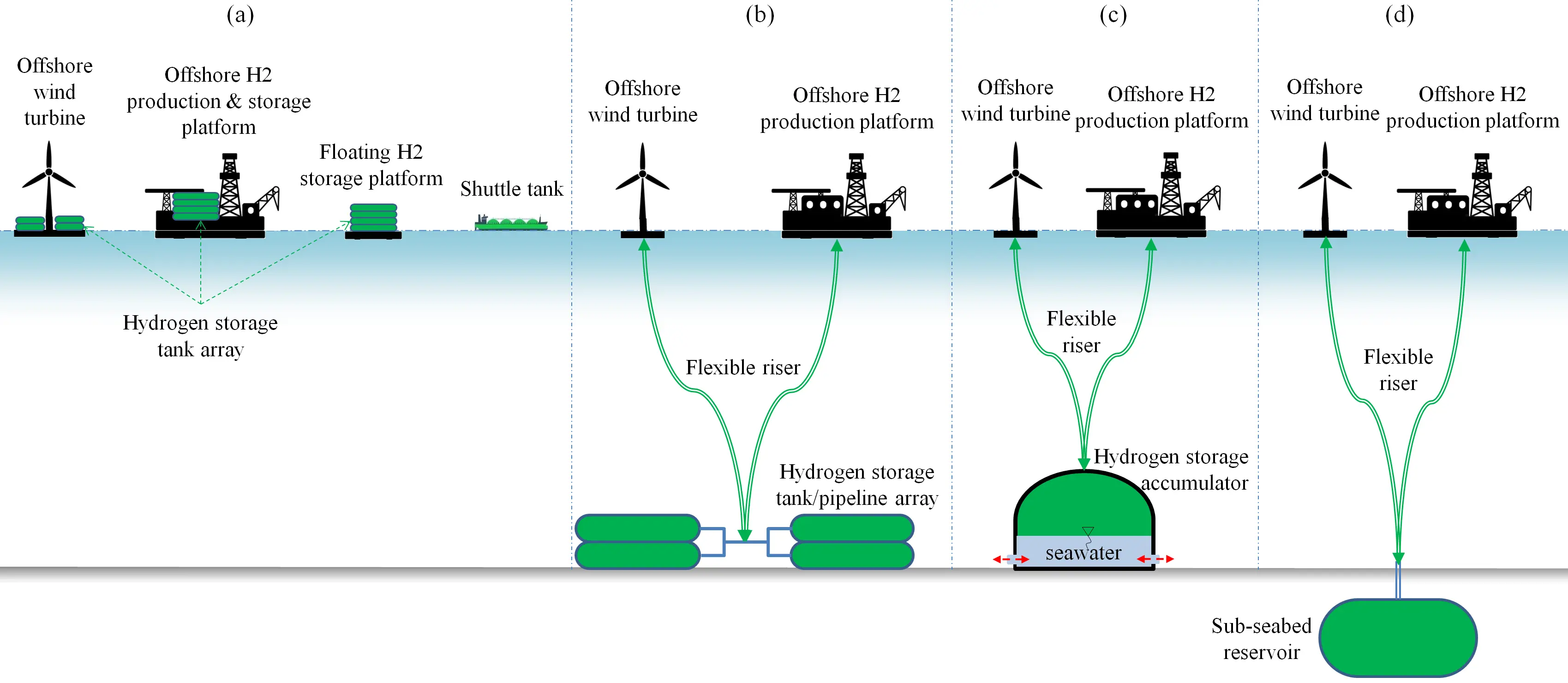
Figure 1. Potential solutions of offshore hydrogen storage: (a) floating/onboard storage; (b) subsea tank storage; (c) subsea isobaric storage; (d) subsea geological storage.
As an emerging technological solution, subsea isobaric hydrogen storage has received limited research attention to date. A detailed investigation on the origin and development of subsea isobaric hydrogen storage can be found in reference [4]. Wang et al. developed a concept with a reinforced concrete structure and conducted a CFD simulation and a modal analysis. It revealed that the risk of vortex-induced vibration fatigue damage was very low [15]. Hunt et al. briefly investigated the economy and global potential of isobaric hydrogen storage with gravel and steel pipes in lakes and reservoirs [16]. The results showed that the levelized cost of hydrogen storage could be 0.17 USD/kg H2 at 200 m depth, and the worldwide capacity potential could reach 15,000 TWh. Wang et al. conducted detailed structural design, analysis, and optimization of a subsea compressed hydrogen energy storage accumulator [17,18]. It was found that the structural strength and fatigue life of the designed reinforced concrete accumulator could satisfy the demand for a 30-year lifetime with a daily cycle. Liang et al. conducted several experiments and simulations on gas-liquid two-phase flow patterns in a gas transmission pipeline in subsea compressed gas energy storage system [19,20]. The results provided references for predicting liquid accumulation and avoiding slug flow in subsea gas transmission pipelines. Although several advantages can be benefit from subsea isobaric hydrogen storage and the technical feasibility has been theoretically proven, the techno-economic performance has not yet been investigated in detail. This knowledge gap represents the primary barrier to technological demonstration and industrial adoption. Thus, the aim of this study is to perform a detailed techno-economic assessment of subsea isobaric hydrogen storage from the perspective of life cycle assessment.
The structure of this paper is organized as follow: Section 2 introduces the detailed configuration and working principle of the proposed subsea isobaric compressed hydrogen storage concept. The detailed life-cycle techno-economic assessment model is established in Section 3. The results are presented and discussed, and parameter sensitivity is analyzed in Section 4. Finally, conclusions are highlighted in Section 5.
2. Subsea Isobaric Hydrogen Storage
Figure 2 presents a schematic diagram of a decentralized green hydrogen production system integrated with floating offshore wind farms and subsea isobaric compressed hydrogen storage. The water electrolysis system is deployed on the deck of semi-submersible floating wind turbines. The produced green hydrogen is transmitted to subsea compressed hydrogen storage accumulators via hydrogen risers. A manifold module connects risers and a hydrogen storage accumulator, and hydrogen flows are controlled and distributed via this manifold module. A large mass of compressed hydrogen is isobarically stored in hydrogen storage accumulators. A hydrogen storage accumulator is mainly composed of a gas storage reservoir, a foundation, a flexible bladder, and a central pipeline module. The gas storage reservoir is made of reinforced concrete, which could significantly reduce the investment cost. It is worth noting that the reliability and long lifetime of concrete in ocean engineering have been commercially proven [21,22]. The foundation structure guarantees the reliable anchoring of the whole accumulator by preventing overturn and local scour. The suction foundation presented in Figure 2 is designed for a common soft seabed in deep seas [23]. The suction foundation is generally constructed with steel. For the hard seabed, a gravity foundation is preferred. It should be noted that the hydrogen storage accumulator is not a pressure vessel. Seawater can enter into and be extruded from the gas storage reservoir in the charging and discharging processes, thereby keeping the pressure of the storage hydrogen constant. The pressure of storage hydrogen is equal to the static pressure of the surrounding seawater. That is, the deeper the accumulator is deployed, the higher the storage pressure is. A flexible bladder, which is made of flexible composite membrane material, is used for separating stored hydrogen and seawater. Similar flexible bladders have been widely used in ocean engineering for underwater lifting and salvage. The membrane can significantly reduce the self-discharge rate of stored hydrogen because the permeability of the flexible bladder is much lower than that of concrete. More importantly, the pollution of seawater on hydrogen can be avoided. A central pipeline module is designed to keep the shape of the flexible bladder controllable in cyclic operations. Besides, the condensed and accumulated water can be removed via the central pipeline module. Therefore, the isobaric hydrogen storage accumulator can be operated daily, weekly, and even monthly, thereby achieving flexible-time and large-scale hydrogen storage. When needed, the stored compressed hydrogen is exported via subsea pipeline and shuttle tanks. It can serve as the energy storage hub for various offshore applications, such as offshore oil and gas production [24] and offshore charging stations [25], etc.
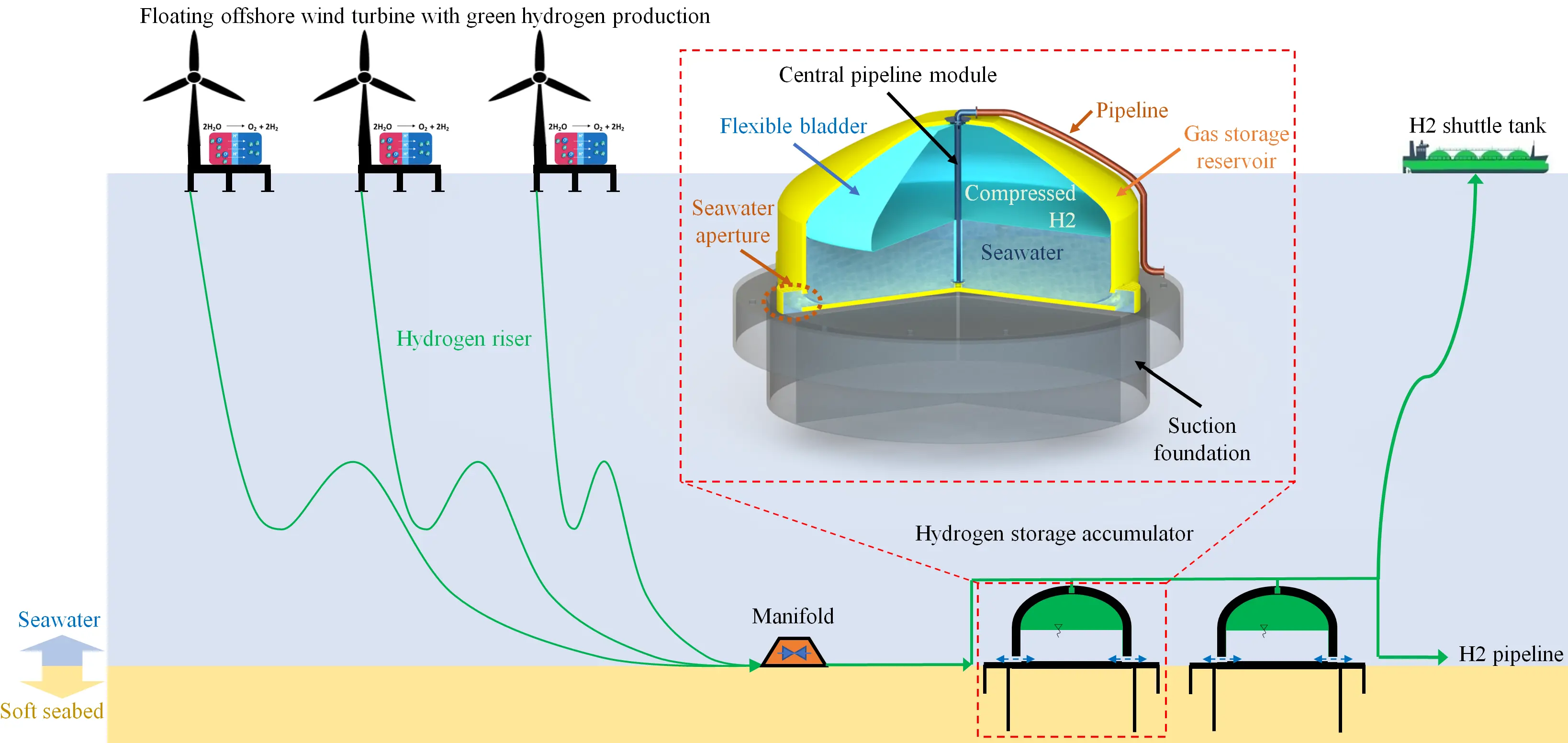
Figure 2. Schematic diagram of a decentralized green hydrogen production system with subsea isobaric hydrogen storage.
3. Techno-Economic Model
In this study, only the subsea hydrogen storage system is focused, while wind turbine, hydrogen production, and hydrogen delivery are not considered. The life cycle of the subsea hydrogen storage system is briefly introduced, and a detailed techno-economic model is established.
3.1. Life Cycle of the Subsea Hydrogen Storage System
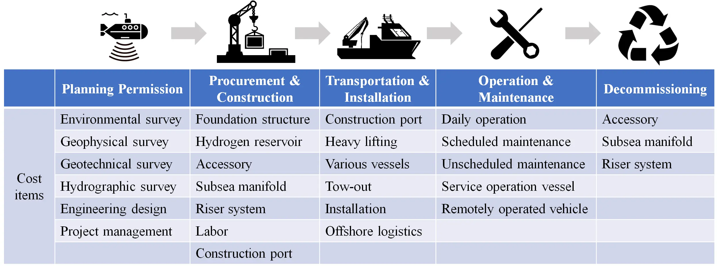
Figure 3 shows the life cycle activities and corresponding cost items of the subsea isobaric hydrogen storage system. Overall, the life cycle of a subsea isobaric hydrogen storage system can be divided into five phases: planning permission, procurement and construction, transportation and installation, operation and maintenance, and decommissioning. It should be noted that these activities should be synchronized with floating offshore wind farms, thereby improving the economic performance throughout the life cycle.
3.1.1. Planning Permission
Receiving planning permission is the first step of the development of a floating offshore wind farm. As an integrated part of a floating offshore wind farm, the subsea hydrogen storage system can share the data and outcomes of development and project management processes, including environmental impact assessments, resource and metocean assessments, geological and hydrographical surveys, and engineering and consultancy, etc.
Subsea hydrogen storage involves greater seabed area utilization, thereby involving a greater seabed footprint. Therefore, more sophisticated environmental surveys should be conducted, especially the benthic species and habitat surveys. This also means additional moderate costs are necessary. Similarly, additional geotechnical surveys are needed to specify the detailed soil and rock strata boundaries and properties at the site where subsea hydrogen storage accumulators are to be accommodated. Generally, drilling boreholes is necessary to collect soil and rock samples at each site, which adds to the costs. Besides, additional costs should be taken in terms of engineering design and project management of subsea hydrogen storage systems. The data of sea floor bathymetry, water depth, soil stratigraphy, and sedimentation environment, etc., from geophysical surveys and hydrographic surveys can be shared with the wind farm development teams, and additional costs can be avoided.
3.1.2. Procurement and Construction
As illustrated in Figure 2, the subsea isobaric hydrogen storage system is mainly composed of a hydrogen storage accumulator, a hydrogen riser, and various accessories. The riser system and many accessories (buoyancy modules, dynamic bend stiffener, touchdown and abrasion protection, connectors, etc.) are commercially available and can be purchased directly from specialized offshore equipment manufacturers. The large-scale hydrogen storage accumulator with a storage volume of 104 m3 shall be constructed in the port prior to deployment.
Material selection for constructing a hydrogen storage accumulator can be either steel, concrete, or a hybrid of the two. Generally, concrete is much cheaper than steel. The price of concrete tends to be more stable than that of steel. And marine concrete is likely to be less vulnerable to corrosion. Although the subsea isobaric hydrogen storage accumulator is not a pressure vessel, it must withstand large tensile stresses due to the buoyancy force of compressed hydrogen in water. Concrete possesses much lower tensile strength than steel. Therefore, the hydrogen storage reservoir is constructed with reinforced concrete. The gravitational fundamental structure can be constructed with concrete, and the suction fundamental structure can be constructed with steel. In this study, only the suction fundamental structure is investigated because it tends to be more expensive, and the suitable soft seabed conditions are more common in deep seas.
A flexible bladder, which is made of flexible composite membrane material, is also a critical component of isobaric hydrogen storage accumulators. Similar materials and designs can be referred to as lift bags, widely used in ocean engineering, marine salvage, and rescue [26,27,28]. It is manufactured in a factory and assembled at the construction port. It is designed to be easily replaced with ROVs (Remotely Operated Vehicles) if damaged.
3.1.3. Transportation and Installation
Once ready, the hydrogen storage accumulators will be towed-out to the wind farm site and installed subsea. The tow-out strategy depends on many factors, such as the scale of the hydrogen storage accumulator, heavy lifting capacity, water depth in port, and weather windows, etc. The tow-out processes are similar for floating offshore wind turbines; however, the weight and draft of hydrogen storage accumulators tend to be larger than those of floating offshore wind turbines.
In this study, the transportation and installation processes of subsea hydrogen storage accumulators are designed as follows. After the construction is complete, the subsea hydrogen storage accumulator is floated in the construction dock. And then the accumulator is towed out to the installation site by tugs, including a primary tug and two support tugs. With the help of heavy lifting vessel, the accumulator is deployed onto the seabed. After that, the riser system will be installed and connect the accumulators and floating wind turbines.
3.1.4. Operations and Maintenance
Operations encompass the management of the subsea hydrogen storage system, including control, operations, monitoring, and administration. It should be integrated into the operations and maintenance of floating offshore wind farms, thereby reducing the costs.
Maintenance of the subsea hydrogen storage system can be divided into scheduled preventive maintenance and unscheduled maintenance. The scheduled maintenance mainly includes inspection and cleanliness of accumulators and risers. This is completed with ROVs annually. The integrality of accumulators and risers, the burial depth and corrosion of suction foundations, and the state of the sacrificial anodes in the galvanic anode cathodic protection systems are generally inspected. In terms of the subsea hydrogen storage system, the flexible bladders inside the accumulators may be the weak links. Therefore, the unscheduled maintenance is supposed to focus on the replacement of the flexible bladders. A conservative reference value of five years is assumed in this study. That is, the flexible bladder will be replaced every five years with the help of ROVs.
3.1.5. Decommissioning
Removal and recycling of the risers, subsea manifold, flexible bladders, central pipeline modules, and accessories are necessary at the end of the useful lifetime of subsea hydrogen storage systems. While the reinforced concrete hydrogen storage accumulators could be left stay in the sites, because a new ecological balance could be rebuilt during the lifetime of service. This new ecological balance means that the functions of biodiversity and productivity normally function instead of returning to the exact original pre-operated conditions [29,30,31,32,33]. The rebalanced ecosystem will be destroyed, and it will cost more time to reach another new ecological balance if the hydrogen storage accumulators are removed in decommissioning. Nevertheless, more efforts and measures should be taken to design for eco-friendliness in the first place.
Besides, the lifetime of the reinforced concrete hydrogen storage accumulators shall be longer than the designed lifetime of floating offshore wind turbines, therefore, these hydrogen storage accumulators could continue to serve the updated floating offshore wind farms.
3.2. Modeling of Levelized Cost of Storage
The levelized cost of hydrogen storage is defined as
|
```latex\mathrm{L}\mathrm{C}\mathrm{O}\mathrm{S}=\frac{\mathrm{C}\mathrm{A}\mathrm{P}\mathrm{E}\mathrm{X}+\mathrm{O}\mathrm{P}\mathrm{E}\mathrm{X}+\mathrm{D}\mathrm{E}\mathrm{E}\mathrm{X}}{\mathrm{T}\mathrm{o}\mathrm{t}\mathrm{a}\mathrm{l}\,\mathrm{ }\mathrm{m}\mathrm{a}\mathrm{s}\mathrm{s}\mathrm{ }\,\mathrm{o}\mathrm{f}\mathrm{ }\,\mathrm{s}\mathrm{t}\mathrm{o}\mathrm{r}\mathrm{e}\mathrm{d}\,\mathrm{ }{\mathrm{H}}_{2}\mathrm{ }\,\mathrm{i}\mathrm{n}\mathrm{ }\,\mathrm{l}\mathrm{i}\mathrm{f}\mathrm{e}\,\mathrm{ }\mathrm{c}\mathrm{y}\mathrm{c}\mathrm{l}\mathrm{e}}``` |
(1) |
where CAPEX is the total capital expenditure of all activities in the phases of planning permission, procurement, and construction, and transportation and installation, OPEX is the operational expenditure of all activities in the phase of operations and maintenance, and DEEX is the decommissioning expenditure, as shown in Equation (2), Equation (3) and Equation (4). It should be noted that the levelized cost of hydrogen storage differs from the levelized cost of hydrogen. The revenue from hydrogen sales is not taken into consideration and only the expenditure about the hydrogen storage system in the life time is considered when calculating the levelized cost of hydrogen storage [34,35,36]. It is worth noting that, in this study, all costs are confirmed and balanced according to References [37,38,39,40,41] and business inquiries. Cost information varies significantly across countries and markets; therefore, compromise values are adopted in this study.
|
```latex\mathrm{C}\mathrm{A}\mathrm{P}\mathrm{E}\mathrm{X}={C}_{\mathrm{P}\mathrm{P}}+{C}_{\mathrm{P}\mathrm{C}}+{C}_{\mathrm{T}\mathrm{I}}``` |
(2) |
|
```latex\mathrm{O}\mathrm{P}\mathrm{E}\mathrm{X}={C}_{\mathrm{O}\mathrm{P}}``` |
(3) |
|
```latex\mathrm{D}\mathrm{E}\mathrm{E}\mathrm{X}={C}_{\mathrm{D}\mathrm{E}}``` |
(4) |
where C means the cost, subscripts PP, PC, TI, OP and DE represent planning permission, procurement and construction, transportation and installation, operations and maintenance, and decommissioning, respectively.
Hydrogen storage demands are mainly decided by the features of floating offshore wind farms. In this study, the basic parameters of floating offshore wind farm and subsea isobaric hydrogen storage are shown in Table 1. It should be noted that the values of different parameters vary for different offshore wind farms. Capacity factor can be regarded as the ratio between the actual output capacity over some time to its maximum capacity under optimum conditions. The capacity factor for offshore wind farms in deep sea is generally much higher than nearshore and onshore counterparts. According to statistics, the capacity factor in offshore wind farms generally ranges from 35% to 65% [42,43,44].
Table 1. Basic parameters of floating offshore wind farm and subsea isobaric hydrogen storage.
|
Parameters |
Symbol |
Benchmark Value |
Unit |
|---|---|---|---|
|
Power capacity of wind farm |
$${P}_{\mathrm{W}\mathrm{F}}$$ |
1000 |
MW |
|
Distance to shore |
D |
100 |
km |
|
Water depth |
H |
400 |
m |
|
Water temperature near the seabed |
T |
5 |
°C |
|
Capacity factor |
k |
0.5 |
/ |
|
Storage volume of hydrogen accumulator |
$${V}_{\mathrm{a}\mathrm{c}\mathrm{c}}$$ |
10,000 |
m3 |
|
Specific energy consumption of hydrogen production |
$${e}_{\mathrm{H}2}$$ |
5 |
kWh/m3 |
|
Lifetime of hydrogen accumulator |
$${n}_{\mathrm{a}\mathrm{c}\mathrm{c}-\mathrm{l}\mathrm{t}}$$ |
30 |
year |
|
Cycling rate of hydrogen accumulator |
$${n}_{\mathrm{a}\mathrm{c}\mathrm{c}-\mathrm{c}\mathrm{r}}$$ |
52 |
per annum |
3.2.1. Required Number of Hydrogen Storage Accumulator
In this study, hydrogen is regarded as an ideal gas. The density of stored hydrogen in the accumulators can be calculated by
|
```latex{\rho }_{\mathrm{H}2}=\frac{{p}_{0}+{\rho }_{\mathrm{w}\mathrm{a}\mathrm{t}\mathrm{e}\mathrm{r}}gH}{{R}_{g}T}``` |
(5) |
where $$\rho$$ is the density, $${p}_{0}$$ is the atmospheric pressure, $$g$$ is the gravitational acceleration, and $${R}_{g}$$ is the gas constant of hydrogen.
The total mass (unit: tons) of annual hydrogen production can be determined by
|
```latex{m}_{\mathrm{H}2}=\frac{24×365×k{P}_{\mathrm{W}\mathrm{F}}}{12.2×{e}_{\mathrm{H}2}}``` |
(6) |
where the number of 12.2 means the volume of 1 kg H2 is 12.2 m3 at a temperature of 25 °C and a standard atmospheric pressure.
The total number of hydrogen storage accumulators can be determined with
|
```latexN=⌈\frac{1000×{m}_{\mathrm{H}2}}{{n}_{\mathrm{a}\mathrm{c}\mathrm{c}-\mathrm{c}\mathrm{r}}{\rho }_{\mathrm{H}2}{V}_{\mathrm{a}\mathrm{c}\mathrm{c}}}⌉``` |
(7) |
where the mathematical operator "$$⌈⌉$$" means round up to an integer.
The total mass (unit: kg) of stored H2 in life cycle can be calculated with
|
```latex{M}_{\mathrm{H}2}=1000×{m}_{\mathrm{H}2}{n}_{\mathrm{a}\mathrm{c}\mathrm{c}-\mathrm{l}\mathrm{t}}``` |
(8) |
3.2.2. Cost of Planning Permission
The total capital expenditure of all activities in the phase of planning permission is determined by
|
```latex{C}_{\mathrm{P}\mathrm{P}}={C}_{\mathrm{E}\mathrm{S}}+{C}_{\mathrm{G}\mathrm{S}}+{C}_{\mathrm{E}\mathrm{D}}+{C}_{\mathrm{P}\mathrm{M}}``` |
(9) |
where subscripts $$\mathrm{E}\mathrm{S}$$, $$\mathrm{G}\mathrm{S}$$, $$\mathrm{E}\mathrm{D},$$ and $$\mathrm{P}\mathrm{M}$$ represent environmental survey, geotechnical survey, engineering design, and project management, respectively.
Thanks to the shared data from planning permission of floating offshore wind farms, the corresponding costs of subsea hydrogen storage can be significantly reduced, especially the costs for environmental survey, engineering design, and project management. The benchmark values are shown in Table 2.
A comprehensive geological survey is essential for the subsequent design and installation of subsea structures. Generally, subsea-bottom profiling, drilling, and geotechnical testing should be conducted. Herein, subsea bottom profiling is the first step in designing offshore wind farms. The data could also be shared when planning subsea hydrogen storage systems. For each hydrogen storage accumulator, additional drilling and testing should be conducted and paid for. The additional cost (unit: 104 $) of geological survey is estimated by
|
```latex{C}_{\mathrm{G}\mathrm{S}}=N\left(5+1×⌈\frac{H}{100}-1⌉\right)``` |
(10) |
where N is the total number of subsea hydrogen storage accumulator, and H is the water depth of storage with unit m.
Table 2. Benchmark values of various cost items involved in subsea isobaric hydrogen storage.
|
Phases |
Cost Items |
Symbol |
Unit Price |
Quantity |
|---|---|---|---|---|
|
Planning permission |
Environmental survey |
$${C}_{\mathrm{E}\mathrm{S}}$$ |
1.5 × 10⁶ [$] |
1 |
|
Geotechnical survey |
$${C}_{\mathrm{G}\mathrm{S}}$$ |
$$\left(5+⌈H/100-1⌉\right)$$ × 104 [$] |
$$N$$ |
|
|
Engineering design |
$${C}_{\mathrm{E}\mathrm{D}}$$ |
8 × 10⁵ [$] |
1 |
|
|
Project management |
$${C}_{\mathrm{P}\mathrm{M}}$$ |
8 × 10⁵ [$] |
1 |
|
|
Procurement and construction |
Foundation structure |
$${C}_{\mathrm{F}\mathrm{S}}$$ |
1500 [$/ton] |
$$0.2{V}_{\mathrm{a}\mathrm{c}\mathrm{c}}N$$ [ton] |
|
Hydrogen reservoir: marine concrete |
$${C}_{\mathrm{M}\mathrm{C}}$$ |
200 [$/ton] |
$$0.7{V}_{\mathrm{a}\mathrm{c}\mathrm{c}}N/2.4$$ [ton] |
|
|
Hydrogen reservoir: rebar |
$${C}_{\mathrm{R}\mathrm{B}}$$ |
850 [$/ton] |
$$0.05{V}_{\mathrm{a}\mathrm{c}\mathrm{c}}N$$ [ton] |
|
|
Accessory: flexible bladder |
$${C}_{\mathrm{F}\mathrm{B}}$$ |
100 [$/m2] |
$$2000N$$ [m2] (about 2000 m2 for an accumulator of 10,000 m3) |
|
|
Accessory: central pipeline module |
$${C}_{\mathrm{C}\mathrm{P}}$$ |
5 × 10⁴ [$] |
$$N$$ |
|
|
Accessory: hydrogen pipeline |
$${C}_{\mathrm{H}\mathrm{P}}$$ |
250 [$] |
$$100N$$ [m] |
|
|
Subsea manifold |
$${C}_{\mathrm{M}\mathrm{F}}$$ |
1.5 × 10⁵ [$] |
$$⌈N/4⌉$$ |
|
|
Flexible riser |
$${C}_{\mathrm{F}\mathrm{R}}$$ |
4.5 × 10⁵ [$/km] |
$$2HN/1000$$ [km] |
|
|
Labor |
$${C}_{\mathrm{L}\mathrm{B}}$$ |
2 × 10⁵ [$] |
$$N$$ |
|
|
Construction port rent |
$${C}_{\mathrm{P}\mathrm{R}}$$ |
2 × 10⁵ [$] |
$$10N$$ [Days] |
|
|
Transportation and installation |
Construction port operation |
$${C}_{\mathrm{P}\mathrm{O}}$$ |
3 × 10⁵ [$/Day] |
$$3N$$ [Days] |
|
Crane vessel |
$${C}_{\mathrm{C}\mathrm{V}}$$ |
4 × 10⁵ [$/Day] |
$$3N⌈\frac{\frac{D}{v}}{24}+2⌉$$ [Days] |
|
|
Towing vessel |
$${C}_{\mathrm{T}\mathrm{V}}$$ |
1 × 10⁵ [$/Day] |
$$3N$$ [Days] |
|
|
Installation |
$${C}_{\mathrm{I}\mathrm{S}}$$ |
4 × 10⁵ [$] |
$$N$$ |
|
|
Operations and maintenance |
Daily operation |
$${C}_{\mathrm{D}\mathrm{O}}$$ |
2 × 10⁴ [$/Year] |
$$N$$ [Years] |
|
Scheduled maintenance |
$${C}_{\mathrm{S}\mathrm{M}}$$ |
5 × 10⁴ [$] |
$$N⌊{n}_{\mathrm{a}\mathrm{c}\mathrm{c}-\mathrm{l}\mathrm{t}}/s-1⌋$$ |
|
|
Unscheduled maintenance |
$${C}_{\mathrm{U}\mathrm{M}}$$ |
5 × 10⁵ [$] |
$$N⌊{n}_{\mathrm{a}\mathrm{c}\mathrm{c}-\mathrm{l}\mathrm{t}}/u-1⌋$$ |
|
|
Decommissioning |
Decommissioning |
$${C}_{\mathrm{D}\mathrm{E}}$$ |
2 × 10⁵ [$/Day] |
$$2N$$ [Days] |
3.2.3. Cost of Procurement and Construction
The total capital expenditure of all activities in the phase of procurement and construction is determined by Equation (11). The detailed meaning of each cost item can be found in Table 2.
|
```latex{C}_{\mathrm{P}\mathrm{C}}={C}_{\mathrm{F}\mathrm{S}}+{C}_{\mathrm{M}\mathrm{C}}+{C}_{\mathrm{R}\mathrm{B}}+{C}_{\mathrm{F}\mathrm{B}}+{C}_{\mathrm{C}\mathrm{P}}+{C}_{\mathrm{H}\mathrm{P}}+{C}_{\mathrm{M}\mathrm{F}}+{C}_{\mathrm{F}\mathrm{R}}+{C}_{\mathrm{L}\mathrm{B}}+{C}_{\mathrm{P}\mathrm{R}}``` |
(11) |
The following assumptions are made when determining the quantity of required materials. The mass of the foundation structure is assumed to be about 20% of the maximum buoyancy force of stored compressed gas. The mass of marine concrete is estimated to be about 70% of the maximum buoyancy force of stored compressed gas. The mass of rebar used for reinforced concrete is about 5% of the maximum buoyancy force of stored compressed gas. It is assumed that four accumulators share a subsea manifold. The length of the flexible riser for each hydrogen accumulator is assumed to be two times of water depth. It is estimated that 10 days would be required to construct and assemble a hydrogen accumulator.
3.2.4. Cost of Transportation and Installation
The total capital expenditure of all activities in the phase of transportation and installation is determined by Equation (12). The detailed meaning of each cost items can be found in Table 2.
|
```latex{C}_{\mathrm{T}\mathrm{I}}={C}_{\mathrm{P}\mathrm{O}}+{C}_{\mathrm{C}\mathrm{V}}+{C}_{\mathrm{T}\mathrm{V}}+{C}_{\mathrm{I}\mathrm{S}}``` |
(12) |
The following assumptions are made in the transportation and installation processes. The hydrogen accumulator is being towed out to the wind farm using 3 towing vessels and deployed onto the seabed with the help of a crane vessel. For each accumulator, it is assumed that one day is required for preparation before towing out, one day is required for preparation before installation, and one day is required for installation. By taking 1/3 of the inappropriate weather windows into consideration, 3 days of rental of a crane vessel are necessary for each hydrogen accumulator. The total rental duration of towing vessels shall be $$3N⌈D/v/24+2⌉$$, where N is the total number of subsea hydrogen storage accumulators, D is the distance to shore, and $$v$$ is the towing speed. In this study, the towing speed is assumed to be 4 kn, which is about 7.408 km/h. It should be noted that the day rates for different vessels are rather volatile and affected by various factors in different markets and times.
3.2.5. Cost of Operations and Maintenance
The total capital expenditure of all activities in the phase of operations and maintenance is determined by
|
```latex{C}_{\mathrm{O}\mathrm{M}}={C}_{\mathrm{D}\mathrm{O}}+{C}_{\mathrm{S}\mathrm{M}}+{C}_{\mathrm{U}\mathrm{M}}``` |
(13) |
where subscripts $$\mathrm{D}\mathrm{O}$$, $$\mathrm{S}\mathrm{M}$$, and $$\mathrm{U}\mathrm{M}$$ represent daily operation, scheduled maintenance, and unscheduled maintenance, respectively. Overall, the operations and maintenance of the subsea hydrogen storage system should be coordinated with those of floating offshore wind farms, thereby significantly reducing the costs of subsea hydrogen storage system operations and maintenance. Daily operation costs much less than maintenance. The maintenance can be divided into scheduled maintenance and unscheduled maintenance. The scheduled maintenance of subsea hydrogen storage system is preferred to be carried out during the periods of scheduled maintenance of wind turbines. The total times of scheduled maintenance of the subsea hydrogen storage system can be determined with $$N⌊{n}_{\mathrm{a}\mathrm{c}\mathrm{c}-\mathrm{l}\mathrm{t}}/s-1⌋$$, where $$s$$ is the frequency of scheduled maintenance and is assumed to be once each year in this study, and symbol $$⌊⌋$$ represents round down to an integer. The unscheduled maintenance is conducted to repair unscheduled faults. The flexible bladders inside accumulators are the most expensive and vulnerable in the subsea hydrogen storage system. Thus, in this study, it is assumed that the flexible bladders are replaced every five years. The total times of unscheduled maintenance of flexible bladders can be determined with $$N⌊{n}_{\mathrm{a}\mathrm{c}\mathrm{c}-\mathrm{l}\mathrm{t}}/u-1⌋$$, where $$u$$ is the frequency of unscheduled maintenance and is assumed to be once each 5 years in this study.
3.2.6. Cost of Decommissioning
The decommissioning of subsea hydrogen storage system is much easier than that of floating offshore wind turbines. The flexible risers, subsea manifold, flexible bladders, central pipeline modules, and accessories will be removed and recycled, while the reinforced concrete hydrogen storage accumulators could be left stay at the sites. It is assumed that two days are cost for decommissioning one set of subsea hydrogen storage systems.
4. Results and Discussion
In this section, the levelized cost of hydrogen storage in a subsea isobaric hydrogen storage system is calculated and compared with that of other hydrogen storage methods in the literature. Besides, parameter sensitivity analysis is conducted to discuss how the levelized cost of storage of hydrogen is affected by various parameters.
4.1. Levelized Cost of Hydrogen Storage
With the established techno-economic model and benchmark parameters as shown in Table 1 and Table 2, it is revealed that 71,803 tons of green hydrogen can be produced, and 40 subsea isobaric hydrogen accumulators are necessary for hydrogen storage following Equation (5), Equation (6), Equation (7) and Equation (8). The life cycle cost of each set subsea hydrogen storage accumulator is about $15 million. Figure 4 shows the costs distribution of subsea isobaric hydrogen storage when integrated with floating offshore wind farms from a life cycle perspective. Figure 5, Figure 6 and Figure 7 show the detailed costs distribution in different phases. It is evident that cost in procurement and construction phase takes the largest proportion. According to Figure 5, the cost of foundation structure takes the largest proportion with a value of 34.07% mainly because of the high cost of steel. A foundation structure made of reinforced concrete and steel-concrete composite structure could be a more economical option [22,45,46]. The cost in transportation and installation phase accounts for 23% due to the high cost of ocean engineering, which is generally neglected in offshore energy storage studies [16,47,48]. From Figure 6, the cost of crane vessel used for lifting in the installation process takes the largest proportion with a share of 35.29% because of the high daily rate of heavy-duty crane vessels. This part can be significantly optimized by using light duty crane vessel, or even eliminating the crane vessel. The cost in the operations and maintenance phase accounts for 26.81% of the whole life cycle costs. From Figure 7, unscheduled maintenance of flexible bladders accounts for about 63% of the cost in the operations and maintenance phase, which is overestimated in our conservative evaluation.
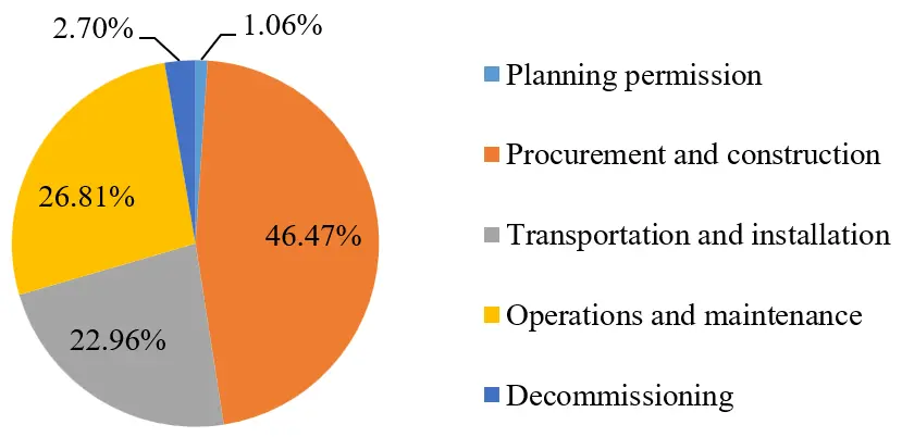
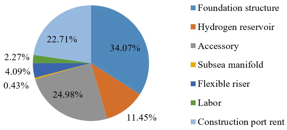
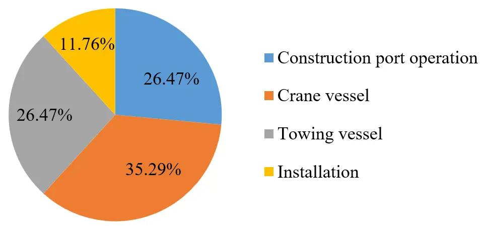
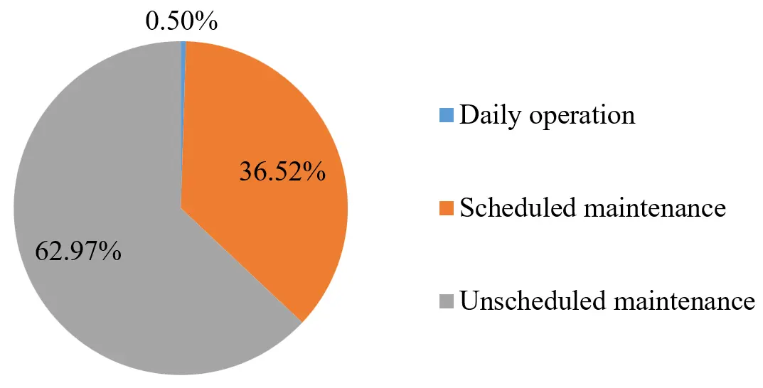
Figure 8 shows the levelized cost of hydrogen storage in various water depths. It is evident that the levelized cost of hydrogen storage decrease with increasing water depth. It is because the pressure and energy density of compressed hydrogen increase with increasing water depth of storage. The deeper, the more hydrogen can be stored in an accumulator. The levelized cost of hydrogen storage is about 0.27 $/kg H2 when the water depth of storage is 400 m.
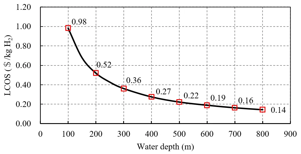
Table 3 shows the levelized cost of hydrogen storage in different storage options. By comparing Figure 8 with Table 3, it can be concluded that the LCOS (0.52 $/kg H2) in subsea isobaric hydrogen storage is much lower than that (1.33 $/kg H2) in the most commonly used pressurized containers. This conclusion remains valid even when the water depth of storage in subsea isobaric hydrogen storage system is 100 m with corresponding LCOS of 0.98 $/kg H2. It should be noted that the LCOS of hydrogen in pressurized containers is evaluated with onshore commercial high-pressure containers. The practical LCOS of hydrogen in pressurized containers shall be much higher for offshore applications by considering the harsh marine environment of storms, vibration, and corrosion, etc. Therefore, we believe subsea isobaric hydrogen storage is economically attractive. When the water depth of storage is larger than 500 m, the LCOS in subsea isobaric hydrogen storage could even be lower than that in salt caverns. Besides, by optimizing the structure, installation, and unscheduled maintenance of subsea isobaric hydrogen storage accumulator, the LCOS in subsea isobaric hydrogen storage can be further reduced. If the usage of steel of foundation structure is reduced by 2/3, the crane vessel is eliminated, and the flexible bladder is replaced each ten years, the LCOS will be reduced from 0.52 $/kg H2 to 0.36 $/kg H2 when the water depth is 200 m, and the cycling rate is one week.
As shown in Table 3, compared with techno-economic analysis of underwater isobaric hydrogen storage conducted by Hunt et al. [16], the LCOS in this study is much higher than Hunt et al.’s results. There are mainly two reasons. First, the design of the isobaric hydrogen storage accumulator differs between the two studies. Second, the techno-economic model is more detailed, and more practical factors are considered in this study.
Table 3. Levelized cost of hydrogen storage in different storage options [16,49].
|
Gaseous State |
Liquid State |
||||||||||
|---|---|---|---|---|---|---|---|---|---|---|---|
|
Storage options |
Salt cavern |
Depleted gas field |
Rock cavern |
Pressurized container |
Subsea isobaric storage accumulator |
Liquid hydrogen |
Ammonia |
Liquid Organic Hydrogen Carrier |
|||
|
Capacity of storage |
0.3~10 × 103 tons per cavern |
0.3 × 10³~1 × 10⁴ tons per field |
0.3~2.5 × 10³ tons per cavern |
5~1.1 × 10³ kg per container |
4~200 tons per accumulator |
0.2~200 tons per tank |
1~10 × 103 tons per tank |
0.18~4.5 × 10³ tons per tank |
|||
|
This study |
[16] |
||||||||||
|
Cycling rate |
Weekly~monthly |
Seasonal |
Weekly~monthly |
Daily |
Weekly |
Daily |
Weekly |
Seasonal |
Daily~weekly |
Weekly~monthly |
Weekly~monthly |
|
Benchmark LCOS ($/kg H2) |
0.23 |
1.90 |
0.71 |
0.19 |
1.33 |
0.076 |
0.52 |
0.17 |
4.57 |
2.83 |
4.50 |
|
Possible future LCOS ($/kg H2) |
0.11 |
1.07 |
0.23 |
0.17 |
1.19 |
0.053 |
0.36 |
N/A |
0.95 |
0.87 |
1.86 |
|
Geographical availability |
Limited |
Limited |
Limited |
Not limited |
Limited |
Not limited |
Not limited |
Not limited |
|||
Note: (1) Levelized cost of storage is evaluated at the highest reasonable cycling rate if not specified. (2) For subsea isobaric hydrogen storage, the water depth of storage is 200 m.
4.2. Sensitivity Analysis
In this sub-section, the effects of various factors on the LCOS of subsea isobaric hydrogen storage are investigated and discussed.
4.2.1. Distance to Shore
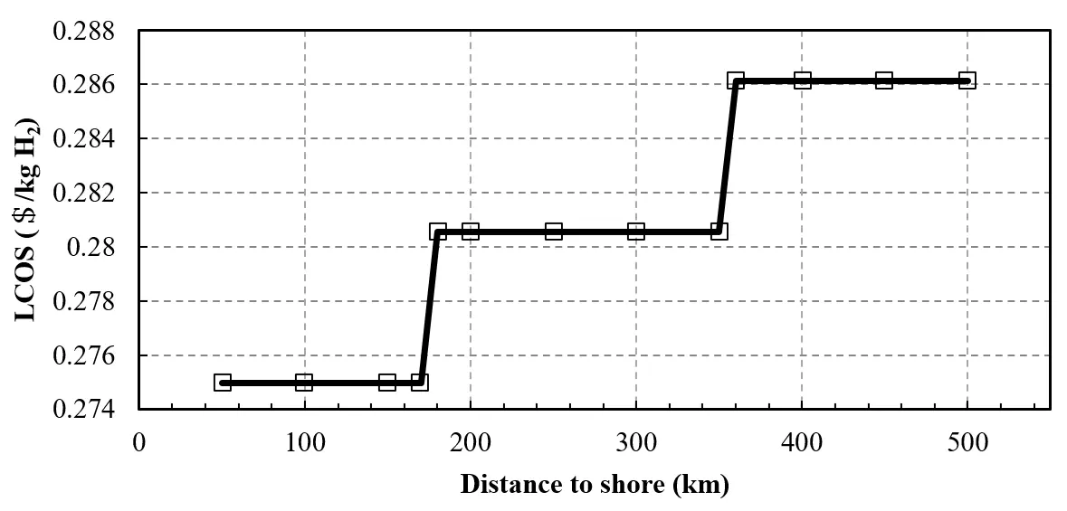
In Table 1, the benchmark value of distance to shore is 100 km. Figure 9 shows the LCOS of hydrogen at different distances from shore in the range of from 50 km to 500 km. It presents an obvious step form. The reason is that the distance to shore only affects the cost of transporting and installing the subsea isobaric hydrogen storage system. The crane and towing vessels are paid daily rather than hourly. Longer distance to shore means more days are necessary for offshore towing. Nevertheless, the increment of LCOS is very small with a value of 0.011 $/kg H2.
4.2.2. Capacity Factor of Wind Farm
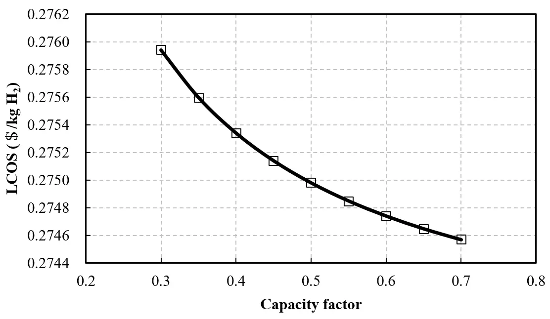
The benchmark value of capacity factor of wind farm is 0.5 in Table 1. Figure 10 shows the LCOS of hydrogen with different capacity factor of the wind farm in the range of from 0.3 to 0.7. It is clear that the LCOS decreases with increasing capacity factor. However, the increment is quite small with a value of 0.001 $/kg H2.
4.2.3. Specific Energy Consumption of Hydrogen Production
In Table 1, the benchmark value of specific energy consumption of hydrogen production is 5 kWh/m3. Figure 11 demonstrates the LCOS of hydrogen across a range of specific energy consumption of hydrogen production (3.5 to 6 kWh/m3). The LCOS fluctuates irregularly with changing specific energy consumption, and the fluctuation range is very small, ranging from 0.006 $/kg H2. Figure 12 shows the corresponding parametric variations in hydrogen storage accumulator requirements. As expected, the annual hydrogen production capacity shows an inverse relationship with specific energy consumption, leading to a proportional decrease in the required number of hydrogen storage accumulators. Notably, the observed trends in LCOS and annual storage capacity per accumulator demonstrate an inverse correlation, indicating that higher per-unit storage volumes correspond to reduced levelized costs.
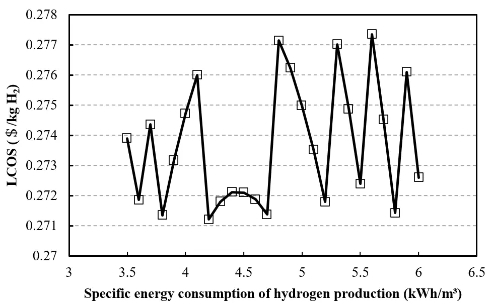
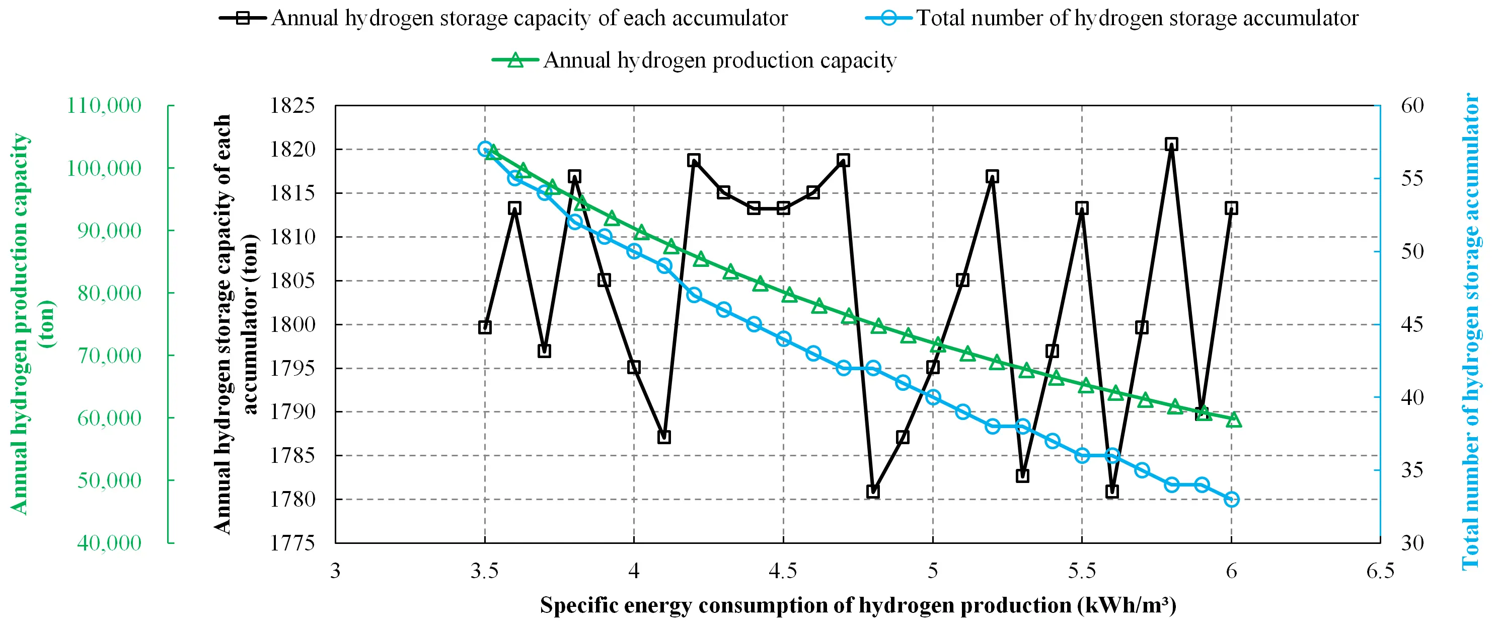
Figure 12. Parameter change of hydrogen storage accumulator with different specific energy consumption of hydrogen production.
4.2.4. Power Capacity of Wind Farm
Figure 13 and Figure 14 show the LCOS of hydrogen and various parameters when the power capacity of wind farm varies between 500 MW and 3500 MW. It is understandable that the annual hydrogen production capacity increases and more hydrogen storage accumulators are necessary when the power capacity of the wind farm increases. The LCOS fluctuates with the changing power capacity of the wind farm. There are two evident step changes when the power capacity of the wind farm reaches 1500 MW and 3100 MW, which is caused by the reduced increment of accumulators from 4 to 3. Besides, the trends of LCOS and the annual hydrogen storage capacity of each accumulator are opposite. This is consistent with that in Figure 11 and Figure 12. However, the LCOS is not solely decided by the annual hydrogen storage capacity of each accumulator because the LCOS gradually decreases with the constant annual hydrogen storage capacity of each accumulator when the power capacity of the wind farm is lower than 1500 MW.
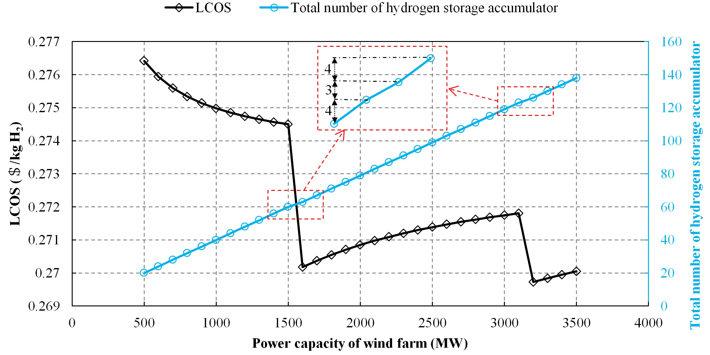
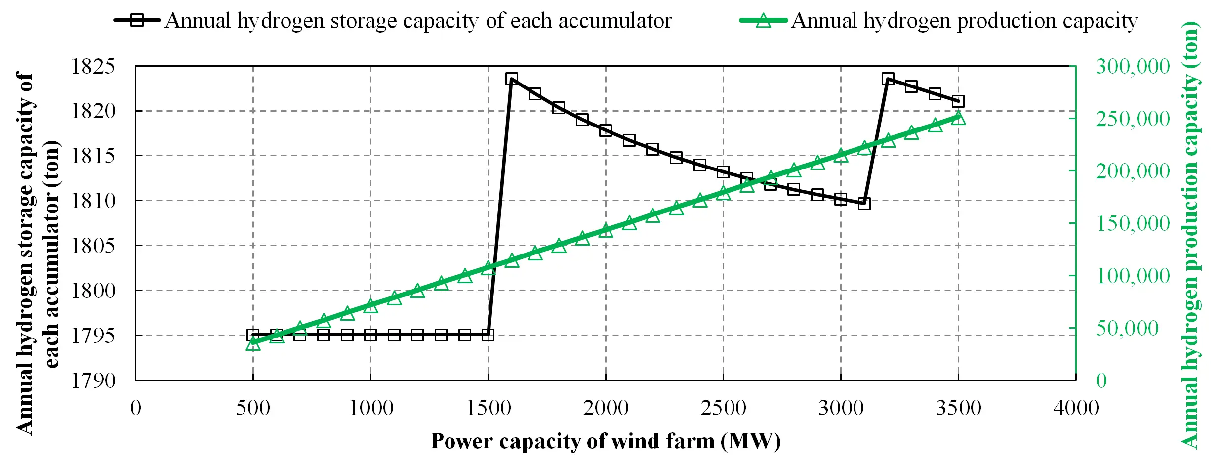
Figure 14. Parameter change of hydrogen storage accumulator with different power capacity of wind farm.
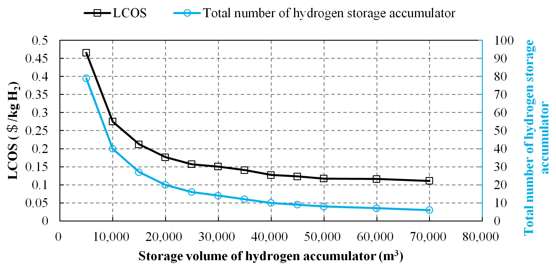
4.2.5. Storage Volume of Single Hydrogen Accumulator
In Table 1, the benchmark value of the storage volume of each hydrogen accumulator is 10,000 m3. Figure 15 shows the LCOS of hydrogen with different storage volumes of each hydrogen accumulator. It is understandable that less hydrogen storage accumulators are required when the storage volume of each hydrogen accumulator is larger. The LCOS of hydrogen decreases with the increasing storage volume of each hydrogen accumulator.
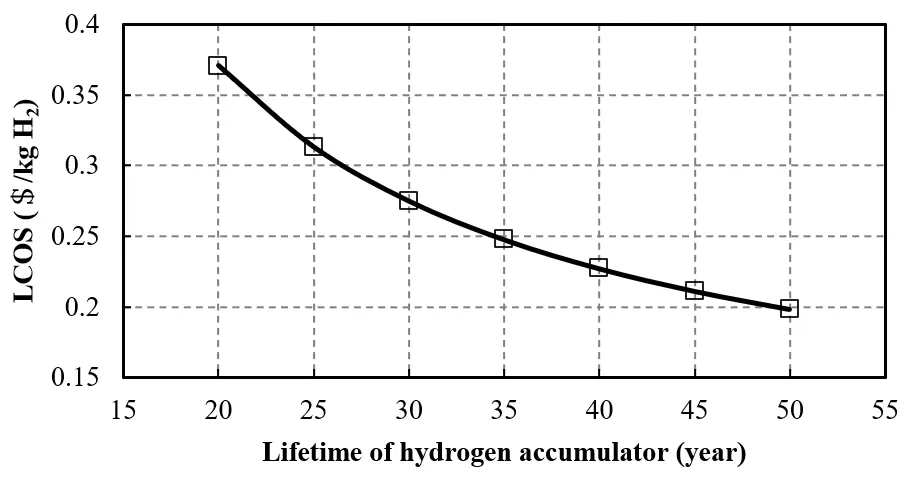
4.2.6. Lifetime of Hydrogen Accumulator
In Table 1, the benchmark lifetime of the hydrogen accumulator is 30 years. Figure 16 shows the LCOS of hydrogen with different lifetime of the hydrogen accumulator. It is clear that the LCOS of hydrogen decreases as the lifetime of the hydrogen accumulator increases, because more hydrogen can be stored when the lifetime is longer.
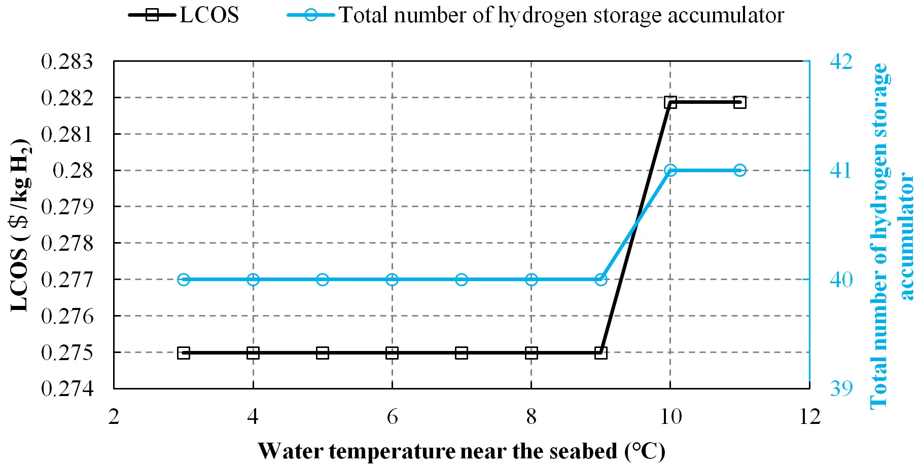
4.2.7. Water Temperature Near the Seabed
Figure 17 shows the LCOS of hydrogen with different water temperatures near the seabed. A noticeable increase occurs when the temperature increases from 9 °C to 10 °C. This is because the density of compressed hydrogen decreases with the increasing temperature and one more hydrogen storage accumulator is required when the temperature exceeds the threshold of 9 °C.
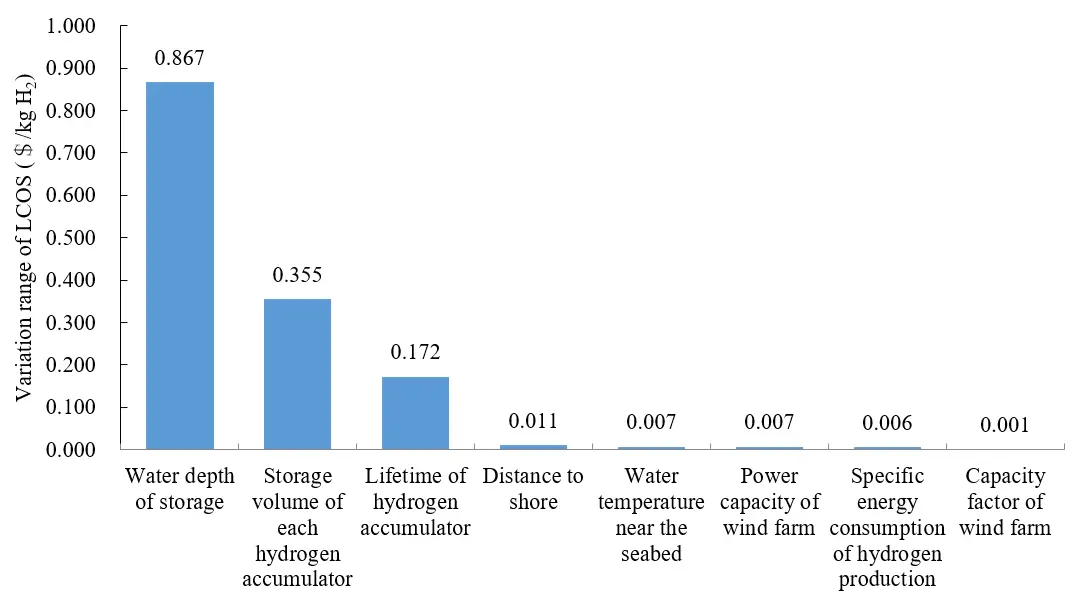
4.2.8. Sensitivity of LCOS to Different Parameters
For simplicity, the sensitivity index is defined by the variation range of LCOS, that is
|
```latexSe={LCOS}_{\mathrm{m}\mathrm{a}\mathrm{x}}-{LCOS}_{\mathrm{m}\mathrm{i}\mathrm{n}}``` |
(14) |
where $${LCOS}_{\mathrm{m}\mathrm{a}\mathrm{x}}$$ is the maximum value of LCOS for a specific parameter, and $${LCOS}_{\mathrm{m}\mathrm{i}\mathrm{n}}$$ is the minimum value of LCOS for a specific parameter.
Figure 18 shows the sensitivity of LCOS to different parameters. It is evident that the LCOS is highly sensitive to the storage water depth, the storage volume of each hydrogen accumulator, and the lifetime each of the hydrogen accumulator. These three parameters are the characteristics of a hydrogen storage accumulator. While the LCOS is much less sensitive to distance to shore, water temperature near the seabed, power capacity of wind farm, specific energy consumption of hydrogen production, and capacity factor of wind farm. These five parameters are the characteristics of a wind farm. This differential sensitivity indicates that while hydrogen accumulator properties predominantly determine LCOS, wind farm characteristics exert only a marginal influence on overall storage economics.
5. Conclusions
The development of offshore wind energy is shifting from near-shallow seas to remote deep seas, thereby challenging the effective and economical transmission and utilization of offshore wind electricity. In this context, green hydrogen production from floating offshore wind has been regarded as a promising alternative to conventional HVDC (High Voltage Direct Current) electricity transmission. Hereinto, large-scale long-duration hydrogen storage is a critical link in the floating offshore wind-based green hydrogen production system. In this study, several gaseous hydrogen storage solutions are summarized and compared briefly, and a novel subsea isobaric hydrogen storage concept is proposed. As an emerging offshore hydrogen storage solution, there remains a research gap in the techno-economic assessment of subsea isobaric hydrogen storage. This issue is solved via this study. The main contribution and findings are summarized as follows.
- (1)
-
A detailed LCOS analysis is conducted on subsea isobaric hydrogen storage from the perspective of the life cycle. The life cycle of the subsea isobaric hydrogen storage system is divided into five phases: planning permission, procurement and construction, transportation and installation, operation and maintenance, and decommissioning. All life-cycle activities and corresponding cost items are considered.
- (2)
-
LCOS of hydrogen in subsea isobaric hydrogen storage system is very attractive compared to conventional solutions. In the benchmark scenario with a weekly cycling rate, the calculated LCOS is 0.27 $/kg H2 and 0.52 $/kg H2 when the water depth of storage is 400 m and 200 m, respectively, which is substantially lower than that of conventional pressurized container storage with the value of 1.33 $/kg H2. When the water depth of storage is larger than 500 m, the LCOS in subsea isobaric hydrogen storage could even be lower than that in salt caverns.
- (3)
-
There are still large spaces for LCOS optimization. About 1/3 of the costs could be reduced by optimizing the high-cost foundation structure, offshore deployment, and flexible bladder. More specifically, when the flexible bladders could be replaced every 10 years, the steel usage for the suction foundation is less by one third, and the utilization of the heavy-duty crane vessel could be avoided. Notably, the transportation and installation costs, often overlooked in existing literature, are found to be significant contributors to overall expenses.
- (4)
-
Sensitivity analysis reveals that the LCOS is primarily determined by the water depth of storage, storage volume of each hydrogen accumulator, and lifetime of the hydrogen accumulator. While the impact of the wind farm on LCOS is marginal. The LCOS decreases with the increasing water depth of storage, larger storage volume of each hydrogen accumulator, and longer lifetime of hydrogen accumulator.
Statement of the Use of Generative AI and AI-Assisted Technologies in the Writing Process
During the preparation of this manuscript, the authors used DeepSeek in order to check spelling, grammar, punctuation, and typographical errors within the manuscript. After using this tool, the authors reviewed and edited the content as needed and take full responsibility for the content of the published article.
Author Contributions
Conceptualization, Z.W., P.L., T.S., D.S.-K.T., R.C. and W.X.; Methodology, Z.W., T.S., D.S.-K.T. and R.C.; Software, Z.W.; Formal Analysis, Z.W., Z.Z., H.W. and P.L.; Investigation, Z.W., Z.Z. and H.W.; Resources, P.L. and W.X.; Data Curation, Z.W., Z.Z. and H.W.; Writing—Original Draft Preparation, Z.W. and Z.Z.; Writing—Review & Editing, T.S., D.S.-K.T., R.C. and W.X.; Visualization, Z.W.; Supervision, W.X.; Project Administration, Z.W. and W.X.; Funding Acquisition, W.X.
Ethics Statement
Not applicable.
Informed Consent Statement
Not applicable.
Data Availability Statement
The data generated during and/or analyzed during the current study are available from the corresponding author on request.
Funding
This research was funded by the National Natural Science Foundation of China [No. 52075065].
Declaration of Competing Interest
The authors declare that they have no known competing financial interests or personal relationships that could have appeared to influence the work reported in this paper.
References
- Wang Z, Carriveau R, Ting DSK, Xiong W, Wang Z. A review of marine renewable energy storage. Int. J. Energy Res. 2019, 43, 6108–6150. DOI:10.1002/er.4444 [Google Scholar]
- Yao Y, Zi M, Niu M, Ye H, Duan J, Chen D. Investigation of scaling criteria and multiscale experiments for hydrate-based CO2 sequestration in marine sediment and depleted NGH reservoir via CO2/N2 injection. Chem. Eng. Sci. 2025, 316, 121912. DOI:10.1016/j.ces.2025.121912 [Google Scholar]
- Aziz MJ, Gayme DF, Johnson K, Knox-Hayes J, Li P, Loth E, et al. A co-design framework for wind energy integrated with storage. Joule 2022, 6, 1995–2015. DOI:10.1016/j.joule.2022.08.014 [Google Scholar]
- Wang Z, Wang H, Sant T, Zhao Z, Carriveau R, Ting DSK, et al. Subsea energy storage as an enabler for floating offshore wind hydrogen production: Review and perspective. Int. J. Hydrogen Energy 2024, 71, 1266–1282. DOI:10.1016/j.ijhydene.2024.05.329 [Google Scholar]
- Giampieri A, Ling-Chin J, Roskilly AP. Techno-economic assessment of offshore wind-to-hydrogen scenarios: A UK case study. Int. J. Hydrogen Energy 2024, 52, 589–617. DOI:10.1016/j.ijhydene.2023.01.346 [Google Scholar]
- Ning M, Yao Y, Zhan Y, Pan F, Fu Y, Chen D, et al. Hydrogen Production from Marine Renewable Energy: A Review. Energies 2025, 18, 6490. DOI:10.3390/en18246490 [Google Scholar]
- Haffaf A, Lakdja F. Mega-scale solar-wind complementarity assessment for large-scale hydrogen production and storage (H2PS) in Algeria: A techno-economic analysis. Int. J. Hydrogen Energy 2024, 86, 985–1009. DOI:10.1016/j.ijhydene.2024.08.443 [Google Scholar]
- Balaji RK, You F. Sailing towards sustainability: Offshore wind’s green hydrogen potential for decarbonization in coastal USA. Energy Environ. Sci. 2024, 17, 6138–6156. DOI:10.1039/D4EE01460J [Google Scholar]
- Yang X, Nielsen CP, Song S, McElroy MB. Breaking the hard-to-abate bottleneck in China’s path to carbon neutrality with clean hydrogen. Nat. Energy 2022, 7, 955–965. DOI:10.1038/s41560-022-01114-6 [Google Scholar]
- Oni BA, Sanni SE, Misiani AN. Green hydrogen production in offshore environments: A comprehensive review, current challenges, economics and future-prospects. Int. J. Hydrogen Energy 2025, 12, 277–309. DOI:10.1016/j.ijhydene.2025.03.429 [Google Scholar]
- Pegler DL, Greaves D, Rawlinson-Smith R, Michele S, Conley D, Benhin J. Techno-economic analysis for floating offshore wind and offshore green hydrogen. Int. J. Hydrogen Energy 2025, 103, 538–555. DOI:10.1016/j.ijhydene.2025.01.172 [Google Scholar]
- Paulino de Azevedo JH, Pradelle F, Botelho V, Torres Serra E, Nohra Chaar Pradelle R, Leal Braga S. An integrated geospatial model for evaluating offshore wind-to-hydrogen technical and economic production potential in Brazil. Int. J. Hydrogen Energy 2025, 100, 800–815. DOI:10.1016/j.ijhydene.2024.12.333 [Google Scholar]
- Ibrahim OS, Singlitico A, Proskovics R, McDonagh S, Desmond C, Murphy JD. Dedicated large-scale floating offshore wind to hydrogen: Assessing design variables in proposed typologies. Renew. Sustain. Energy Rev. 2022, 160, 112310. DOI:10.1016/j.rser.2022.112310 [Google Scholar]
- Hassanpouryouzband A, Joonaki E, Edlmann K, Haszeldine RS. Offshore geological storage of hydrogen: Is this our best option to achieve net-zero? ACS Energy Lett. 2021, 6, 2181–2186. DOI:10.1021/acsenergylett.1c00845 [Google Scholar]
- Wang Z, Wang J, Cen H, Ting DSK, Carriveau R, Xiong W. Large-eddy simulation of a full-scale underwater energy storage accumulator. Ocean Eng. 2021, 234, 109184. DOI:10.1016/j.oceaneng.2021.109184 [Google Scholar]
- Hunt JD, Nascimento A, Romero OJ, Zakeri B, Jurasz J, Dąbek PB, et al. Hydrogen storage with gravel and pipes in lakes and reservoirs. Nat. Commun. 2024, 15, 7723. DOI:10.1038/s41467-024-52237-1 [Google Scholar]
- Wang H, Xiong W, Liang C, Carriveau R, Ting DSK, Wang Z. Design and modal analysis of a large-scale underwater compressed gas energy storage accumulator. In Proceedings of the 7th Offshore Energy & Storage Symposium (OSES 2023), St. Julian’s, Malta, 12–14 July 2023. DOI:10.1049/icp.2023.1549 [Google Scholar]
- Wang H, Wang Z, Ting DSK, Carriveau R, Sant T, Xiong W. Structural strength and fatigue analyses of large-scale underwater compressed hydrogen energy storage accumulator. Mar. Struct. 2024, 98, 103684. DOI:10.1016/j.marstruc.2024.103684 [Google Scholar]
- Liang C, Xiong W, Carriveau R, Ting DSK, Wang Z. Experimental and modeling investigation of critical slugging behavior in marine compressed gas energy storage systems. J. Energy Storage 2022, 49, 104038. DOI:10.1016/j.est.2022.104038 [Google Scholar]
- Liang C, Xiong W, Wang H, Carriveau R, Ting DSK, Li P, et al. Identification and maximum impact force modeling investigation for critical slugging in underwater compressed gas energy storage systems. J. Energy Storage 2023, 67, 107550. DOI:10.1016/j.est.2023.107550 [Google Scholar]
- Pérez Fernández R, Lamas Pardo M. Offshore concrete structures. Ocean Eng. 2013, 58, 304–316. DOI:10.1016/j.oceaneng.2012.11.007 [Google Scholar]
- Mathern A, von der Haar C, Marx S. Concrete Support Structures for Offshore Wind Turbines: Current Status, Challenges, and Future Trends. Energies 2021, 14, 1995. DOI:10.3390/en14071995 [Google Scholar]
- Wang H, Wang Z, Zhao Z, Ting DSK, Sant T, Carriveau R, et al. An experimental investigation of the pullout capacity of a composite suction caisson for underwater compressed hydrogen energy storage accumulator in saturated sand. Ocean Eng. 2025, 327, 121010. DOI:10.1016/j.oceaneng.2025.121010 [Google Scholar]
- Riboldi L, Pilarczyk M, Nord LO. The Impact of Process Heat on the Decarbonisation Potential of Offshore Installations by Hybrid Energy Systems. Energies 2021, 14, 8123. DOI:10.3390/en14238123 [Google Scholar]
- Li R, Li H, Huang W, Tao H, Xu W, Tai N, et al. Accelerating green shipping with spatially optimized offshore charging stations. Nat. Energy 2025, 10, 243–254. DOI:10.1038/s41560-024-01692-7 [Google Scholar]
- Liu C, Su X, Yin Z, Sheng Y, Zhou X, Xu Y, et al. Experimental study on the feasibility of isobaric compressed air energy storage as wind power side energy storage. Appl. Energy 2024, 364, 123129. DOI:10.1016/j.apenergy.2024.123129 [Google Scholar]
- Pimm AJ, Garvey SD, de Jong M. Design and testing of Energy Bags for underwater compressed air energy storage. Energy 2014, 66, 496–508. DOI:10.1016/j.energy.2013.12.010 [Google Scholar]
- Sun K, Liu M, Lu C, You Y, Zhang J, Meng W, et al. 2D design and characteristic analysis of an underwater airbag with mooring for underwater compressed air energy storage. Ocean Eng. 2023, 285, 115515. DOI:10.1016/j.oceaneng.2023.115515 [Google Scholar]
- Galparsoro I, Menchaca I, Garmendia JM, Borja Á, Maldonado AD, Iglesias G, et al. Reviewing the ecological impacts of offshore wind farms. NPJ Ocean. Sustain. 2022, 1, 1. DOI:10.1038/s44183-022-00003-5 [Google Scholar]
- ITOFP. Effects of Oil Pollution on the Marine Environment. 2014. Available online: https://www.itopf.org/knowledge-resources/documents-guides/tip-13-effects-of-oil-pollution-on-the-marine-environment/ (accessed on 14 December 2025).
- Watson SCL, Somerfield PJ, Lemasson AJ, Knights AM, Edwards-Jones A, Nunes J, et al. The global impact of offshore wind farms on ecosystem services. Ocean Coast. Manage. 2024, 249, 107023. DOI:10.1016/j.ocecoaman.2024.107023 [Google Scholar]
- Nicolette JP, Nelson NA, Rockel MK, Rockel ML, Testoff AN, Johnson LL, et al. A framework for a net environmental benefit analysis based comparative assessment of decommissioning options for anthropogenic subsea structures: A North Sea case study. Front. Mar. Sci. 2023, 9, 1020334. DOI:10.3389/fmars.2022.1020334 [Google Scholar]
- Carneiro PRF, Fasca H, Cordeiro M, Martingil M, do Valle LV, de Souza MIL, et al. A methodological approach for an objective environmental impact assessment to support the decision-making in the decommissioning of oil and gas subsea installations in Brazil. J. Nat. Conserv. 2024, 79, 126619. DOI:10.1016/j.jnc.2024.126619 [Google Scholar]
- Oueslati F, Toumi N. Technical feasibility and financial assessment of autonomous hydrogen refuelling stations fully supplied by mixed renewable energy systems for twenty selected sites located in France. Environ. Dev. Sustain. 2025, 27, 27957–27995. DOI:10.1007/s10668-024-04872-3 [Google Scholar]
- Oueslati F, Fezai S, Toumi N, Alshehri NA. Sustainable hydrogen refuelling stations: Techno-financial viability across Saudi Arabia. Proc. Inst. Civ. Eng.-Energy 2025, 178, 201–223. DOI:10.1680/jener.23.00061 [Google Scholar]
- Mehr AS, Carton JG. Techno-economic analysis of green hydrogen storage in salt caverns: Evaluating cycling effects and cavern scaling on the levelized cost of hydrogen storage in Ireland’s power-to-X landscape. J. Energy Storage 2025, 136, 118439. DOI:10.1016/j.est.2025.118439 [Google Scholar]
- Bai Y, Bai Q. Subsea Cost Estimation. In Subsea Engineering Handbook, 2nd ed.; Elsevier: Amsterdam, The Netherlands, 2019. DOI:10.1016/B978-0-12-812622-6.00006-3 [Google Scholar]
- BVG Associates. Guide to a Floating Offshore Wind Farm. 2023. Available online: https://tethys.pnnl.gov/sites/default/files/publications/BVG_2023.pdf (accessed on 17 December 2025).
- Centeno-Telleria M, Yue H, Carrol J, Aizpurua JI, Penalba M. O&M-aware techno-economic assessment for floating offshore wind farms: A geospatial evaluation off the North Sea and the Iberian Peninsula. Appl. Energy 2024, 371, 123684. DOI:10.1016/j.apenergy.2024.123684 [Google Scholar]
- Díaz H, Guedes Soares C. Cost and financial evaluation model for the design of floating offshore wind farms. Ocean Eng. 2023, 287, 115841. DOI:10.1016/j.oceaneng.2023.115841 [Google Scholar]
- McMorland J, Collu M, McMillan D, Carroll J. Operation and maintenance for floating wind turbines: A review. Renew. Sustain. Energ. Rev. 2022, 163, 112499. DOI:10.1016/j.rser.2022.112499 [Google Scholar]
- Andrew ZPS. UK Offshore Wind Capacity Factors. 2022. Available online: https://energynumbers.info/uk-offshore-wind-capacity-factors (accessed on 17 December 2025).
- Desalegn B, Gebeyehu D, Tamrat B, Tadiwose T, Lata A. Onshore versus offshore wind power trends and recent study practices in modeling of wind turbines’ life-cycle impact assessments. Cleaner Eng. Technol. 2023, 17, 100691. DOI:10.1016/j.clet.2023.100691 [Google Scholar]
- Thomas B, Costoya X, deCastro M, Iglesias G, Gómez-Gesteira M. Levelized cost of energy for various floating offshore wind farm designs in the areas covered by the Spanish maritime spatial planning. Appl. Energy 2025, 381, 125165. DOI:10.1016/j.apenergy.2024.125165 [Google Scholar]
- Zhang P, Xu Y, Xiao J, Le C, Ding H. Mechanical Characteristics of Prestressed Concrete Curved Transition Section of Composite Bucket Foundations for Offshore Wind Turbines. J. Mar. Sci. Eng. 2022, 10, 473. DOI:10.3390/jmse10040473 [Google Scholar]
- Zhang W, Jing H, Kou H. Effects of Relative Roughness and Particle Size on the Interface Behavior of Concrete Suction Caisson Foundation for Offshore Wind Turbines. Energies 2020, 13, 5866. DOI:10.3390/en13225866 [Google Scholar]
- Guo H, Xu Y, Zhu Y, Zhang X, Yin Z, Chen H. Coupling properties of thermodynamics and economics of underwater compressed air energy storage systems with flexible heat exchanger model. J. Energy Storage 2021, 43, 103198. DOI:10.1016/j.est.2021.103198 [Google Scholar]
- Liu Z, Ding J, Huang X, Liu Z, Yan X, Liu X, et al. Analysis of a hybrid heat and underwater compressed air energy storage system used at coastal areas. Appl. Energy 2024, 354, 122142. DOI:10.1016/j.apenergy.2023.122142 [Google Scholar]
- BloombergNEF. Global Gas Report 2020. 2020. Available online: https://data.bloomberglp.com/professional/sites/24/BNEF-IGU-Snam-2020-Global-Gas-Report_FINAL.pdf (accessed on 7 January 2026).