Research on the Bearing Characteristics of Bucket Foundations for Offshore Wind Turbines in Double-Layered Clay

Research on the Bearing Characteristics of Bucket Foundations for Offshore Wind Turbines in Double-Layered Clay
You Feng 1 Hao Zhang 1 Xiaohe Wang 2,3 Qingtao Zhang 2,4 Jiayu Wang 1,* Run Liu 1,2
Received: 07 January 2026 Revised: 02 February 2026 Accepted: 03 March 2026 Published: 16 March 2026

© 2026 The authors. This is an open access article under the Creative Commons Attribution 4.0 International License (https://creativecommons.org/licenses/by/4.0/).
1. Introduction
With the increasing global demand for clean energy, wind power has gained significant attention as an important new type of clean energy. Offshore wind energy, leveraging superior wind resources over the ocean, has become a focal point of development [1]. As a typical marine engineering structure, the overall service reliability of offshore wind turbine structures is closely related to the mechanical performance of tubular joints [2]. The foundation structure, being the core load-bearing component of offshore wind turbines, plays a decisive role in ensuring construction safety and long-term service life. The bucket foundation, with its advantages such as high overall stiffness, strong anti-overturning capacity, and relatively high construction efficiency, has gradually emerged as a mainstream choice, laying a solid foundation for the large-scale development of offshore wind power [3].
Currently, research on the bearing characteristics of bucket foundations mainly focuses on homogeneous soil conditions, where the ultimate bearing capacity of the foundation has been thoroughly studied [4,5,6]. Gourvenec et al. [7,8] analyzed the foundation bearing capacity and surrounding soil movement of bucket foundations under vertical loading through centrifuge tests; Hung and Kim [9] employed finite element methods to examine the vertical and horizontal bearing capacity of bucket foundations in clay soil, providing corresponding calculation formulas; Liu Run [10] and Wang Jiayu [11] et al. derived the upper-bound solutions for the bearing capacity based on the failure mechanisms of bucket foundations in clay soil.
However, the seabed exhibits complex and variable forms; existing studies have demonstrated that different types of layered soils can significantly affect the ultimate bearing capacity of bucket foundations [12,13,14]. Park et al. [15] investigated the vertical bearing capacity of bucket foundations in sand-over-clay layered soils using numerical analysis methods, and proposed a calculation formula for foundation bearing capacity considering various factors such as clay soil strength and sand layer depth. Zhou [16] and Long et al. [17] analyzed the inclined pullout capacity of suction anchors in layered soils through numerical simulations and proposed an evaluation method for inclined pullout capacity based on V-H envelopes. Zhang [18] explored the horizontal bearing characteristics of modified suction caissons in layered soils through model tests and numerical simulations, studying the effects of load eccentricity and soil layer distribution on lateral bearing capacity, rotation point position, and soil deformation characteristics. Liu et al. [19] employed numerical analysis methods to study the bearing characteristics of square foundations in stiff-over-soft layered clay soils, summarizing the influence patterns of overlying soil layer thickness and the undrained shear strength ratio between upper and lower soil layers on foundation bearing capacity. Ma Pengcheng et al. [20] investigated the effects of different soil layer thicknesses and V-H load combinations on the bearing capacity and optimal loading point position of suction anchor foundations in layered clay soils.
In summary, current research on the bearing characteristics of offshore wind turbine bucket foundation subsoils primarily focuses on single-layer clay soils or sand-clay interbedded conditions; however, stratified clay soil foundations are predominant in offshore areas of China. Therefore, this study employs the finite element method to investigate the bearing characteristics of offshore wind turbine bucket foundations in double-layered clay. Initially, a suitable numerical model is established and validated. Subsequently, the vertical, horizontal, and overturning uniaxial failure modes are revealed, and the influence rules of embedment ratio and soil strength ratio on the uniaxial ultimate bearing capacity are analyzed with corresponding calculation methods developed. Furthermore, the bearing characteristics and failure envelope evolution under two-dimensional combined loads (V-H, V-M, H-M) and three-dimensional V-H-M combined loads are explored.
This study summarizes the core patterns governing the bearing behavior of bucket foundations in double-layered clay. These findings are expected to provide valuable theoretical support and practical guidance for the engineering design of offshore structures in China’s coastal double-layered clay regions.
2. Numerical Analysis Methods
To investigate the bearing characteristics of bucket foundations in double-layer clay, numerical analyses were conducted to determine the foundation bearing capacity at different embedment ratios. All finite element (FE) analyses are carried out with the software ABAQUS by small strain analyses [21]. This assumption is well justified for the load conditions and embedment depths considered in this study, as the dominant failure mechanisms of bucket foundations in clay under typical operational loads are characterized by relatively small soil deformations.
2.1. Finite Element Model Establishment
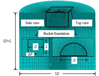
The diameter of the bucket foundation is D = 30 m, with a skirt length of L. The embedment ratio (η = L/D) is set to η = 0.25, 0.5, 0.75, 1, 1.25, 1.5, 1.75, and 2. The skirt thickness ts = 0.3 m. To minimize the influence of boundary effects on calculation results, based on the suggestions of previous scholars [4]. The soil diameter is taken as Dsoil = 5D, and the height Lsoil = 3D + L; The mesh size of the foundation model is set to ζ = 0.03D, while the mesh size in the radial and depth directions of the soil is taken as ζsoil = 0.03D~0.25D, all meshes adopt C3D8 elements.
Due to the inherent symmetry of the structure and to improve computational efficiency, a half-model was adopted for numerical analysis. The bottom of the soil was fully constrained, while the sides were horizontally constrained; symmetric boundary conditions were applied at the soil’s symmetrical boundary, restricting displacement along the normal to the symmetrical plane. The load application point was located at the center of the cylindrical foundation end face, as shown in Figure 1.
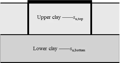
The soil is modeled using an ideal elastic-plastic constitutive model based on the Tresca yield criterion, the submerged unit weight of the soil is taken as γ′ = 6 kN/m3, conforming to the engineering characteristics of coastal soft clay in China; the Poisson’s ratio is υsoil = 0.48, approaching the incompressible state of clay under undrained shear directly affects the stiffness response and stability in numerical calculations, serving as a key parameter controlling model convergence [22,23]. The undrained shear strengths of the upper and lower soil layers are defined as su,top and su,bottom, respectively, where su,top = 10 kPa. The interface between the upper and lower soil layers is located at the tip of the bucket foundation, as shown in Figure 2. The ratio of undrained shear strength between the upper and lower soil layers (S = su,top/su,bottom) is taken as S = 0.1, 0.2, 0.5, 1, 2. The elastic modulus of the soil is taken as Esoil = 500su.
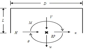
The basic structure adopts a linear elastic model with an elastic modulus of Ebucket = 210 GPa, material density of ρburket = 700 kg/m3, and Poisson’s ratio of υburket = 0.3. The contact type between the bucket foundation and soil is “surface-to-surface contact”, and the contact behavior satisfies the “rough and non-separable” assumption. The displacement control method is used to calculate the ultimate bearing capacity of the bucket foundation, whereas the numerical analysis method complies with the small-displacement assumption. Gravity is applied only to the submerged portion of the bucket foundation below the mudline to ensure the bearing capacity is the net capacity, excluding buoyancy effects. The load application direction follows the recommendations of Butterfield [24], with the sign convention specified in Table 1. RP denotes the load application reference point, as detailed in Figure 3.
Table 1. Load Symbols and Normalization Processing.
|
Vertical |
Horizontal |
Rotational |
|
|---|---|---|---|
|
Load |
V |
H |
M |
|
Displacement |
w |
u |
θ |
|
Uniaxial capacity |
Vult |
Hult |
Mult |
|
Bearing capacity factor |
NcV = Vult/Asu |
NcH = Hult/Asu |
NcM = Mult/ADsu |
|
Normalized load |
v = V/Vult |
h = H/Hult |
m = M/Mult |
Note: A—Cross-sectional area of the bucket foundation.
Through numerical analysis of the bearing capacity of bucket foundations under different working conditions, this study investigates the influence of the undrained shear strength ratio between upper and lower soil layers and the foundation depth-to-diameter ratio on the ultimate bearing capacity of offshore wind turbine bucket foundations.
2.2. Model Validation
- (1)
- To verify the accuracy of the model, the uniaxial ultimate bearing capacity of bucket foundations with different embedment ratios was calculated under homogeneous soil conditions (S = 1). The calculation results were then compared with the research findings from the previous literature Fu [25] and Vulpe [26], with the specific comparison results shown in Table 2.
Table 2. Comparison of Axial ultimate Bearing Capacity Results.
|
η |
Data Source |
NcV |
NcH |
NcM |
|---|---|---|---|---|
|
1/4 |
This study |
8.83 |
3.2 |
1.17 |
|
Fu [25] |
8.61 |
2.81 |
1.02 |
|
|
error |
2.5% |
13.8% |
14.7% |
|
|
Vulpe [26] |
8.75 |
2.82 |
1.01 |
|
|
error |
1.6% |
0.4% |
1% |
|
|
1/2 |
This study |
10.79 |
4.57 |
1.71 |
|
Fu [25] |
10.69 |
4.27 |
1.57 |
|
|
error |
0.9% |
7% |
8.9% |
|
|
Vulpe [26] |
11.29 |
4.15 |
1.47 |
|
|
error |
5.6% |
2.8% |
6.4% |
|
|
3/4 |
This study |
12.51 |
5.76 |
2.56 |
|
Fu [25] |
12.48 |
5.56 |
2.39 |
|
|
error |
0.2% |
3.6% |
7.1% |
|
|
1 |
This study |
13.74 |
7.06 |
3.75 |
|
Fu [25] |
14.02 |
6.65 |
3.60 |
|
|
error |
2% |
6.2% |
4.2% |
The calculation results show a maximum error of 14.7% when compared with previous research findings, demonstrating good consistency and verifying the accuracy of the numerical model.
- (2)
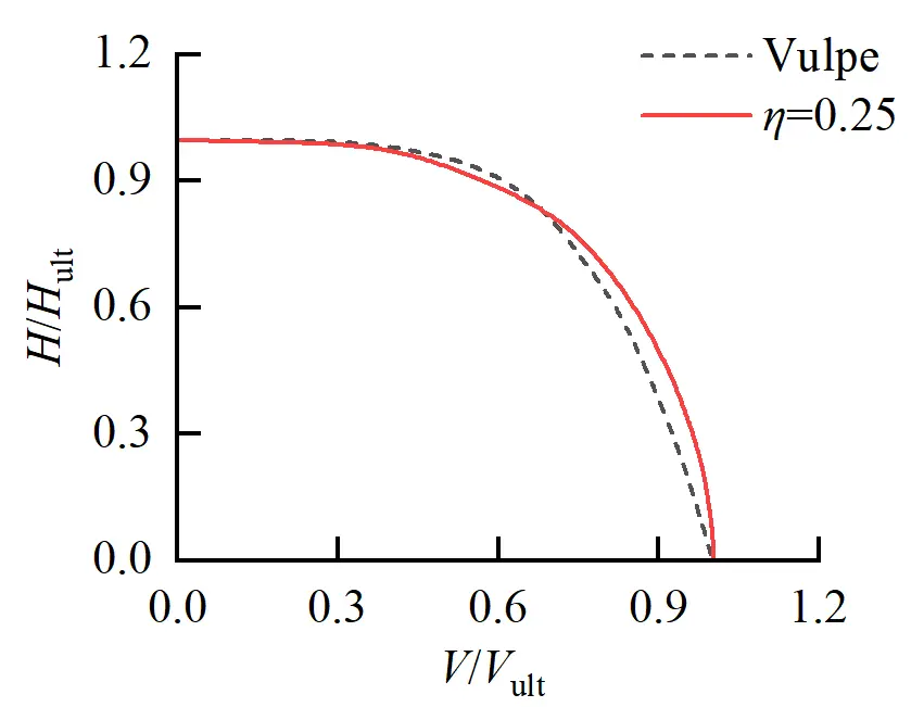
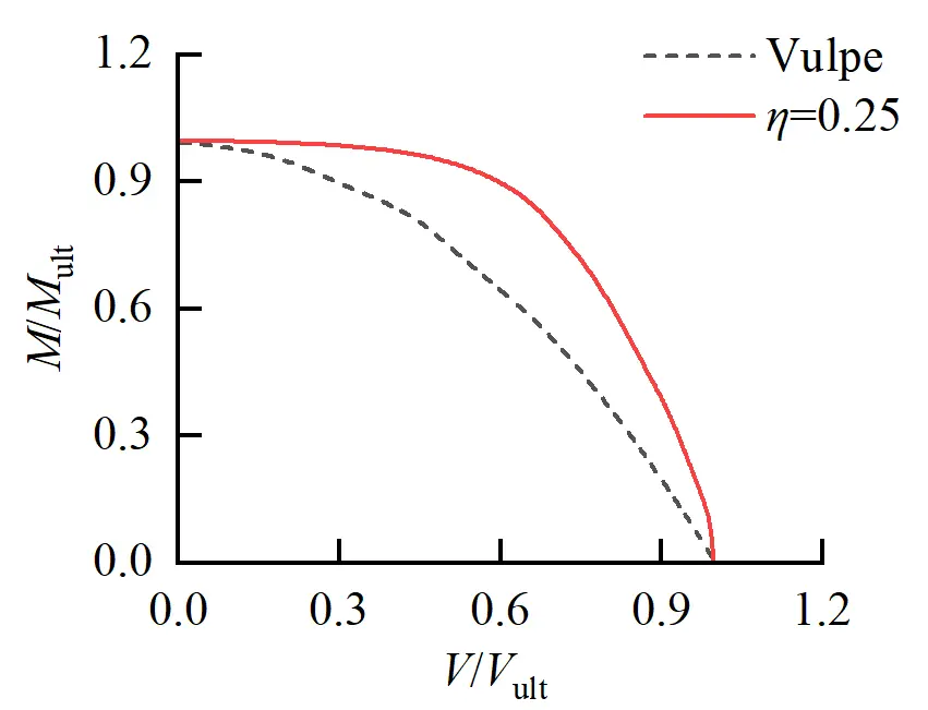
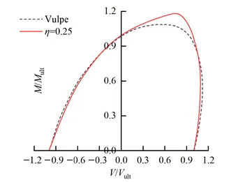
- To further verify the accuracy of the finite element model, based on the numerical model of the bucket foundation at S = 1 and η = 0.25, the fixed displacement method was adopted to simulate the bearing capacity of the composite foundation. The calculation results were compared with those of Vulpe et al., as shown in Figure 4.
 |
 |
|
(a) |
(b) |
 |
|
|
(c) |
|
Figure 4. Comparison of the Bearing Capacity of Composite Foundation. (a) The normalized V-H failure envelope; (b) The normalized V-M failure envelope; (c) The normalized H-M failure envelope.
As can be seen from Figure 4, the envelope generated by finite element calculation shows good agreement with the computational results in the literature, except that the V-M failure envelope is slightly higher than the literature results, which verifies the accuracy of using this numerical analysis model for calculating the bearing capacity of composite foundations with bucket foundations.
In summary, the established finite element model can be used for calculating the ultimate bearing capacity of bucket foundation subgrades.
3. Uniaxial Bearing Performance of Bucket Foundation in Double-Layer Clay Soil
3.1. Uniaxial Failure Mode of Bucket Foundation
The uniaxial failure mode serves as the foundation for studying the uniaxial ultimate bearing capacity of offshore wind turbine bucket foundations. By revealing the failure mechanism of soil-foundation interaction, it can provide a theoretical basis for establishing bearing capacity calculation methods.
3.1.1. Vertical Failure Mode
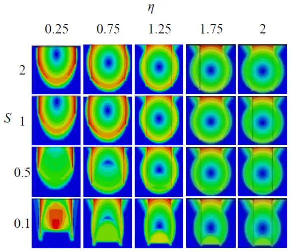
By analyzing the displacement field of the bucket foundation under vertical ultimate load, the variation patterns of foundation failure modes under different depth-diameter ratios and undrained shear strength ratios of soil are discussed, with specific calculation results shown in Figure 5.
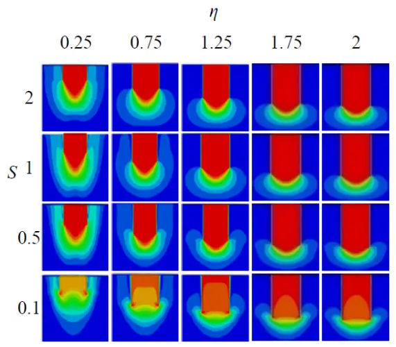
As shown in the figure, the vertical foundation failure mode of the bucket foundation in double-layer soil generally exhibits characteristics of the Prandtl failure mode. Under vertical ultimate load, the soil inside the bucket is constrained by the top cover and side walls, forming an integrated movement trend with the foundation. A distinct rigid zone is observed in the soil within the foundation, and the area of this rigid zone increases with the rise in the foundation’s depth-diameter ratio and undrained shear strength ratio of soil.
When the length-to-diameter ratio of the foundation is small, the skirt plate exerts a relatively weak restraining effect on the soil, allowing it to move laterally and further expanding the soil’s influence range. When the strength of the lower soil layer is significantly greater than that of the upper soil layer, a weak zone forms in the internal soil of the foundation compared to the soil at the ends. Under vertical loading, the foundation cannot effectively transfer the force to the underlying soil, making it difficult for the internal soil to move downward. As a result, the slip surface of the soil begins to develop upward.
3.1.2. Horizontal Failure Mode
By analyzing the displacement field of bucket foundations under horizontal ultimate loads, this study discusses the variation patterns of foundation failure modes under different embedment ratios and undrained shear strength ratios between the upper and lower soil layers. The specific calculation results are shown in Figure 6.
As can be seen from the figure, the foundation failure mode of the bucket foundation under horizontal ultimate load generally exhibits characteristics of the Reserve Scoop failure mode. With the increase of horizontal load, the soil at the end of the bucket foundation first enters the plastic yield state, and the plastic zone continuously develops upward along both sides of the barrel wall. Only when the soil strength is relatively small (S < 0.5), the foundation failure mode manifest as the Internal Hansen failure mode, with the soil’s slip surface intruding into the interior of the foundation.
When the embedment ratio of the foundation is small, the plastic failure zone of the surrounding soil extends to the ground surface. This means the combined effect of the cylindrical foundation’s sidewalls and the soil is relatively weak, and the restraining effect of the sidewalls alone is insufficient to drive the overall movement of the soil inside the cylinder. As the length-to-diameter ratio of the foundation increases, the disturbance to the surrounding soil gradually decreases, and the plastic zone no longer extends to the ground surface, thereby exhibiting characteristics of the Reserve Scoop mode. As the soil strength ratio gradually decreases—meaning the strength of the soil at the base of the cylinder is significantly higher compared to the soil inside the foundation—the slip surface of the soil tends to move inward. This makes the soil more prone to failure inside the foundation, causing the foundation failure mode to manifest as the Internal Hansen mode.
3.1.3. Overturning the Failure Mode
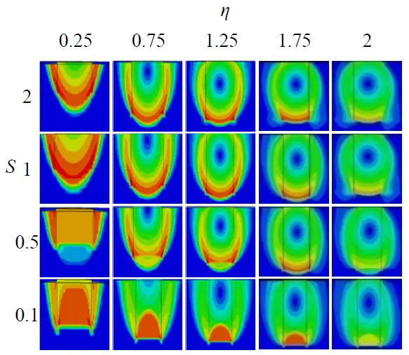
By analyzing the displacement field of bucket foundations under overturning limit loads, this study discusses the variation patterns of foundation failure modes under different embedment ratios and undrained shear strength ratios between upper and lower soil layers. The specific calculation results are shown in Figure 7.
As can be seen from the figure, the failure mode characteristics of bucket foundations under overturning loads mainly involve rotational failure around a certain axis, exhibiting features of Scoop Slide mode, Forward Scoop mode, and Intermal Double Scoop mode, respectively. Under the same undrained shear strength ratio of soil, the failure mode of bucket foundation transitions gradually from Scoop Slide mode to Forward Scoop mode as the embedment ratio increases. Only when the undrained shear strength ratio of soil is relatively small (S < 0.5) does the soil slip surface penetrate the foundation interior, demonstrating characteristics of the Intermal Double Scoop mode.
As the embedment ratio of the foundation increases, the lateral earth pressure on both sides of the cylindrical wall rises, leading to a reduction in the disturbance range around the foundation. This causes the failure mode of the foundation to gradually transition from the Scoop Slide mode to the Forward Scoop mode. When the strength of the internal soil within the foundation is slightly lower than that of the soil at the skirt tip, the slip surface of the soil under overturning loads tends to develop more inward, exhibiting characteristics of the Internal Double Scoop mode.
3.2. Evolution Law of Uniaxial Ultimate Bearing Capacity
The uniaxial ultimate bearing capacity of bucket foundations was normalized using the foundation cross-sectional area, foundation diameter, and undrained shear strength of the soil at the base (su,bottom), the study investigated the evolution patterns of the uniaxial ultimate bearing capacity coefficient with respect to the foundation depth-to-diameter ratio and the undrained shear strength ratio between upper and lower soil layers.
3.2.1. Vertical Ultimate Bearing Capacity
Figure 8 shows the variation curves of the vertical ultimate bearing capacity factor NcV with the undrained shear strength ratio of upper and lower soil layers and the foundation depth-to-diameter ratio.
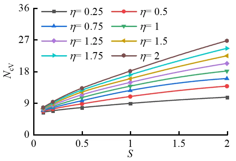
As can be seen from Figure 8, under the condition of the same depth-to-diameter ratio, the undrained shear strength ratio of the upper and lower soil layers has a significant influence on the vertical bearing capacity factor of the foundation. Specifically, with the continuous increase of the undrained shear strength ratio of soil, the vertical bearing capacity factor of the bucket foundation shows an approximately linear growth trend, but the growth rate gradually decreases.
The variation patterns of foundation bearing capacity for bucket foundations in double-layer cohesive soil and single-layer soil are similar. With the increase of depth-to-diameter ratio, the vertical foundation bearing capacity coefficient generally increases. In double-layer clay soil, the vertical foundation bearing capacity coefficient of bucket foundations also improves with the increase of undrained shear strength ratio of soil.
3.2.2. Horizontal Ultimate Bearing Capacity
Figure 9 shows the variation curves of the horizontal ultimate bearing capacity factor NcH with the undrained shear strength ratio of upper and lower soil layers and the foundation depth-to-diameter ratio.
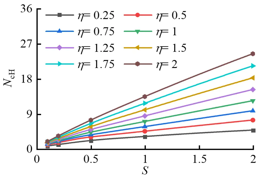
As can be seen from Figure 8, under the condition of the same foundation depth-to-diameter ratio, the horizontal ultimate bearing capacity coefficient of the bucket foundation gradually increases with the continuous increase of the undrained shear strength ratio between the upper and lower soil layers, but the growth rate gradually decreases. Under the condition of the same undrained shear strength ratio of soil, as the foundation depth-to-diameter ratio increases, the horizontal ultimate bearing capacity coefficient of the foundation also increases, but the variation in growth rate is relatively small.
3.2.3. Ultimate Anti-Overturning Bearing Capacity
Figure 10 shows the variation curves of the ultimate anti-overturning bearing capacity coefficient NcM with the undrained shear strength ratio of upper and lower soil layers and the foundation depth-to-diameter ratio.
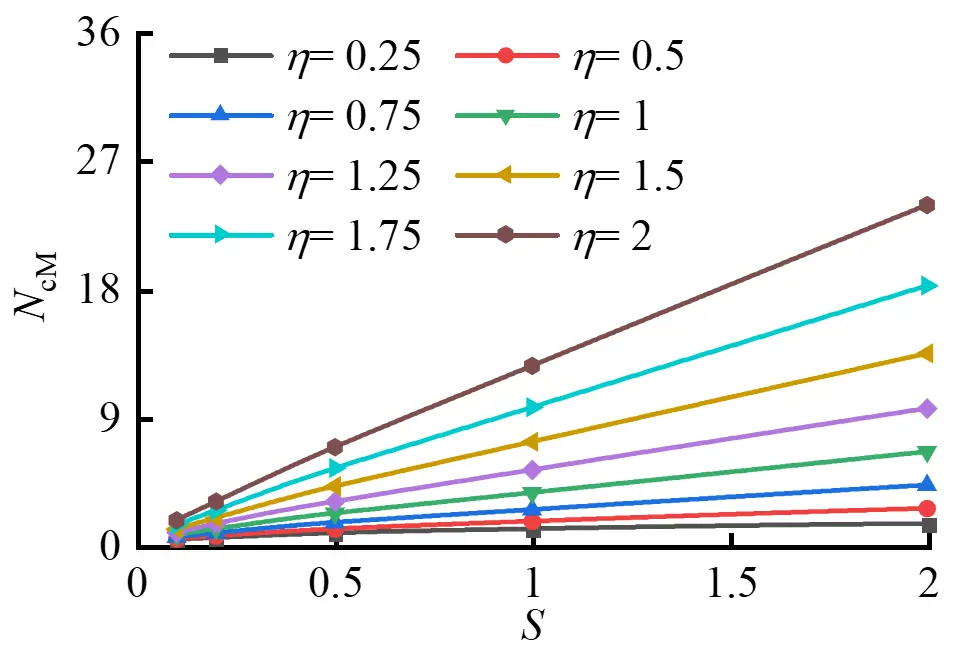
As can be seen from Figure 10, like the variation pattern of horizontal ultimate bearing capacity at the foundation level, the ultimate anti-overturning bearing capacity coefficient of the bucket foundation gradually increases with the continuous growth of undrained shear strength ratio of soil, but the growth rate progressively decreases. As the depth-diameter ratio of the foundation continues to increase, the ultimate anti-overturning bearing capacity coefficient likewise rises, and the growth rate shows some acceleration.
3.3. Calculation Method for Uniaxial Ultimate Bearing Capacity
Based on the calculation results, the evolution law of the uniaxial ultimate bearing capacity coefficient for bucket foundations in double-layered clay soil can be obtained, as specifically illustrated in Figure 11.
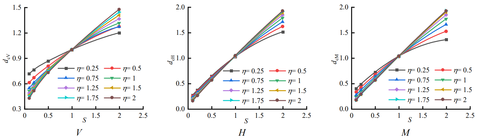
Figure 11. The relationship between the axial bearing capacity correction coefficient and the strength ratio of the upper and lower.
To simplify the calculation method for the uniaxial bearing capacity of bucket foundations in double-layered clay soil, a soil strength correction factor dc for uniaxial ultimate bearing capacity is introduced:
|
```latex{d}_{c}={N}_{c,S}/{N}_{c,S=1}``` |
(1) |
In the formula: Nc,S—uniaxial ultimate bearing capacity coefficient of bucket foundation in double-layer soil; Nc,S=1—uniaxial ultimate bearing capacity coefficient of bucket foundation in single-layer soil.
By applying the least squares method to fit the curve in the figure, the mathematical expression between the uniaxial ultimate bearing capacity correction coefficient dc and the undrained shear strength ratio of the upper and lower soil layers can be obtained:
|
```latex{d}_{c}=a{S}^{2}+bS+c``` |
(2) |
In the equation: a, b, c—fitting parameters. There are significant differences in the fitting results of ultimate bearing capacity in different directions, and the parameter values are correlated with the depth-diameter ratio of the bucket foundation. The specific fitting expressions are as follows:
|
```latex\begin{cases}a_\mathrm{v}=0.06\eta^2-0.15\eta-0.032\\b_\mathrm{v}=-0.18\eta^2+0.58\eta+0.27\\c_\mathrm{v}=0.12\eta^2-0.43\eta+0.76&\end{cases}``` |
(3) |
In the formula: aV, bV, cV—fitting parameters for the vertical ultimate bearing capacity correction coefficient dcV;
|
```latex\begin{cases}a_\mathrm{H}=-0.07\eta^2+0.23\eta-0.24\\b_\mathrm{H}=0.07\eta^2-0.15\eta+1.08\\c_\mathrm{H}=0.01\eta^2-0.09\eta+0.19&\end{cases}``` |
(4) |
In the formula: aH, bH, cH—fitting parameters for the horizontal ultimate bearing capacity correction coefficient dcH;
|
```latex\begin{cases}a_\mathrm{M}=-0.07\eta^2+0.25\eta-0.26\\b_\mathrm{M}=-0.02\eta^2+0.09\eta+0.91\\c_\mathrm{M}=0.1\eta^2-0.36\eta+0.39&\end{cases}``` |
(5) |
In the formula: aM, bM, cM—fitting parameters for the modification coefficient dcM of ultimate anti-overturning bearing capacity.
4. Composite Bearing Capacity of Bucket Foundation in Double-Layer Clay Soil
As a tall structure, wind turbines are subjected to combined environmental loads during operation. The bucket foundation serving as the supporting structure typically uses bearing capacity failure envelopes (surfaces) to characterize its composite bearing performance.
4.1. V-H Two-Dimensional Failure Envelope
Numerical calculations were conducted using the fixed displacement ratio method to analyze the influence of foundation depth-to-diameter ratio and undrained shear strength ratio between upper and lower soil layers on the ultimate bearing characteristics of bucket foundation under V-H combined loading. The normalized V-H failure envelope of the bucket foundation was presented, with specific calculation results shown in Figure 12.
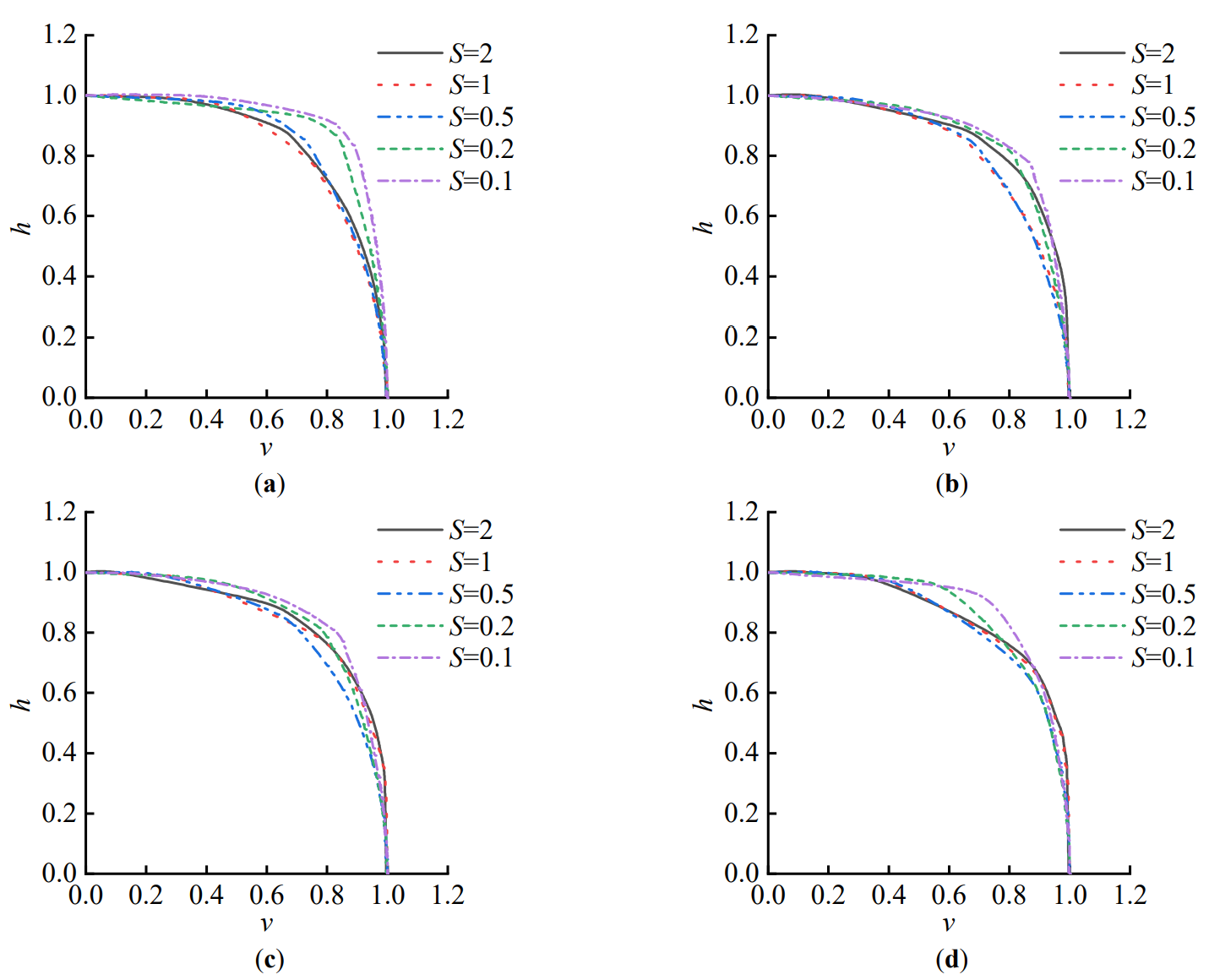
Figure 12. The normalized V-H failure envelope. (a) η = 0.25; (b) η = 0.75; (c) η = 1.25; (d) η = 2.
As shown in Figure 11, within the range of S = 0.1~2, the normalized V-H failure envelope exhibits a significant inward contraction with the continuous increase in the undrained shear strength ratio of the soil. The depth-diameter ratio of the bucket foundation also exerts a certain influence on the failure envelope. Specifically, as the depth-diameter ratio increases, the discrepancy between failure envelopes under different undrained shear strength ratios of soil gradually diminishes. This indicates that a larger depth-diameter ratio can, to some extent, reduce the influence of the undrained shear strength ratio of soil on the shape of the V-H failure envelope.
4.2. V-M Two-Dimensional Failure Envelope
The influence of the foundation depth-to-diameter ratio and the undrained shear strength ratio of the upper and lower soil layers on the V-M bearing capacity characteristics of the composite ground under the bucket foundation was also analyzed. The normalized V-M failure envelope of the bucket foundation was presented, with specific calculation results shown in Figure 13.
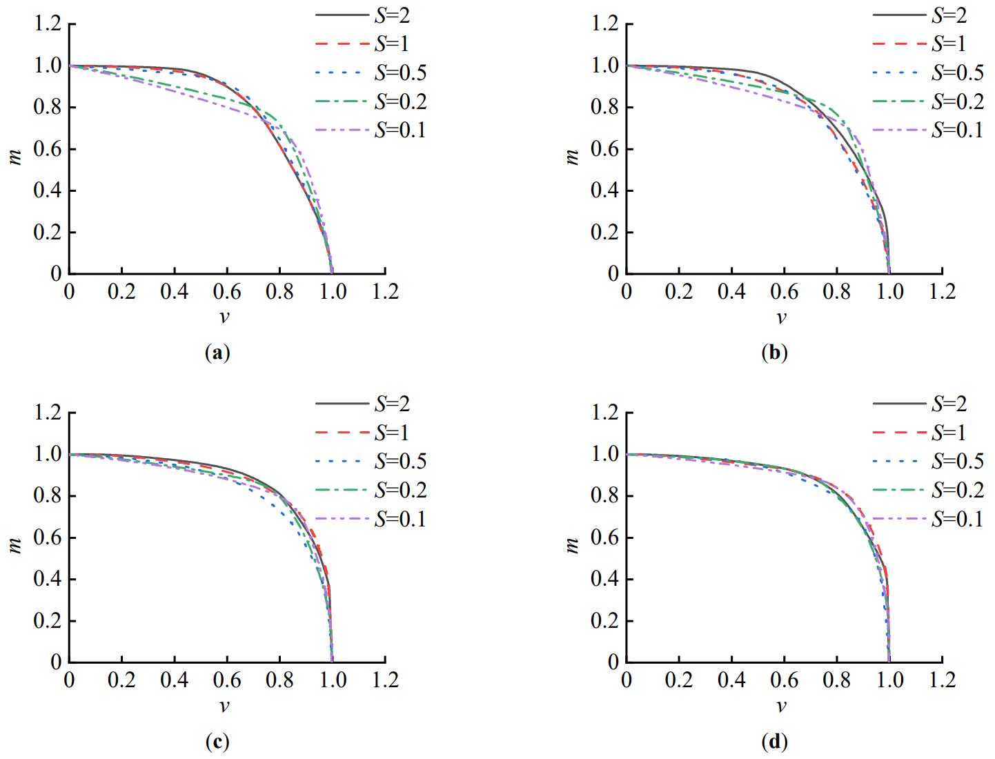
Figure 13. The normalized V-M failure envelope. (a) η = 0.25; (b) η = 0.75; (c) η = 1.25; (d) η = 2.
As shown in Figure 13, within the range of S = 0.1–2, the normalized V-M failure envelope exhibits a clear outward expansion trend as the undrained shear strength ratio of soil increases. When the foundation depth-to-diameter ratio is small (η ≤ 0.75), the shape of the envelope varies significantly with changes in the undrained shear strength ratio of soil, i.e., the smaller the undrained shear strength ratio of soil, the poorer the symmetry of the envelope. However, as the foundation depth-to-diameter ratio increases, the shapes of the envelopes under different undrained shear strength ratios of soil remain largely consistent, indicating that a larger foundation depth-to-diameter ratio can also reduce the influence of the undrained shear strength ratio of soil on the shape of the V-M failure envelope to some extent.
4.3. H-M Two-Dimensional Failure Envelope
Based on the normalized failure envelope of the bucket foundation in the H-M load space, the evolution of the ultimate bearing capacity characteristics of the bucket foundation under H-M combined loading with respect to the depth-to-diameter ratio and the undrained shear strength ratio of upper and lower soil layers can also be obtained, as shown in Figure 14.
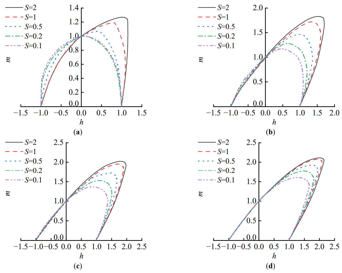
Figure 14. The normalized H-M failure envelope. (a) η = 0.25; (b) η = 0.75; (c) η = 1.25; (d) η = 2.
As shown in Figure 14, within the range of S = 0.1~2, the normalized H-M failure envelope gradually expands outward with the continuous increase of the undrained shear strength ratio of soil, exhibiting a distinct “eccentric” state. When both the foundation depth-to-diameter ratio and undrained shear strength ratio of soil are small (η = 0.25, S ≤ 0.2), the shape of the normalized H-M failure envelope for the bucket foundation approximates a semicircle. However, as the undrained shear strength ratio of soil or foundation depth-to-diameter ratio continues to increase, the H-M envelope gradually transitions from a “semicircular” shape to an “eccentric” state.
4.4. V-H-M Three-Dimensional Failure Envelope Surface
The fixed displacement ratio method was also employed to investigate the bearing capacity envelope surface of bucket foundations in the V-H-M load space, with vertical loads set at V = 0, 0.25 Vult, 0.5 Vult, and 0.75 Vult, respectively. Based on this, the variation patterns of the V-H-M three-dimensional failure envelope surface of bucket foundations with respect to the embedment depth-to-diameter ratio and undrained shear strength ratio of soil were studied. The specific calculation results are shown in Figure 15.
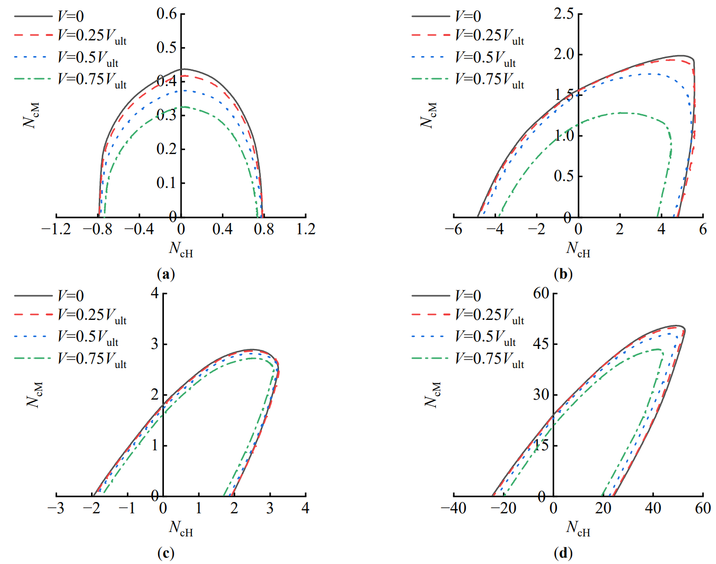
Figure 15. V-H-M failure envelope. (a) η = 0.25, S = 0.1; (b) η = 0.25, S = 2; (c) η = 2, S = 0.1; (d) η = 2, S = 2.
Figure 15 illustrates the size and shape of the failure envelope surfaces for bucket foundations in the V-H-M load space under conditions of embedment ratio η = 0.25, 2, and undrained shear strength ratio of soil S = 0.1, 2. As can be observed from the figure, with increasing vertical load, the H-M failure envelope gradually contracts inward, indicating that the increase in vertical load weakens the bearing capacity of the H-M composite foundation to some extent, while having essentially no effect on the shape of the envelope.
When both the embedment ratio and the undrained shear strength ratio of upper and lower soil layers are small (η = 0.25, S = 0.1), the H-M failure envelopes of bucket foundations under different vertical load levels all exhibit a “semicircular” shape, as shown in Figure 13a. However, with the increase of either the embedment ratio or the undrained shear strength ratio of soil, the H-M failure envelopes of bucket foundations gradually display an “eccentric” pattern, and the degree of “eccentricity” becomes increasingly pronounced. This indicates that in double-layer clay soils, both the undrained shear strength ratio of the upper and lower soil layers and the embedment ratio of the foundation significantly influence the shape of the H-M envelopes of bucket foundations under different vertical load levels.
5. Conclusions
The ultimate bearing capacity of bucket foundations in double-layered clay soil was analyzed using the finite element method. The study systematically investigated the variation patterns of uniaxial and composite ultimate bearing capacities of bucket foundations in double-layered clay soil, while establishing a calculation method for uniaxial ultimate bearing capacity. The main conclusions are as follows:
- (1)
-
The vertical bearing mode of bucket foundations is relatively less affected by the undrained shear strength ratio of soil. The soil inside the bucket is strongly constrained by the foundation skirt, showing a tendency of integral movement with the foundation under vertical loading. The failure mode of the foundation primarily manifests as the Prandtl bearing mechanism.
- (2)
-
The undrained shear strength ratio of soil relatively significantly influences the horizontal failure mode of bucket foundations. As the embedment ratio of the foundation and the undrained shear strength ratio of soil decrease, the restraining capacity of the skirt on the soil inside the bucket gradually weakens, causing the failure mode to progressively transition from the Reserve Scoop mode to the Internal Hansen mode.
- (3)
-
Compared to the undrained shear strength ratio of soil, the depth-to-diameter ratio of the foundation has a more significant influence on the failure modes of bucket foundations under overturning. As the depth-to-diameter ratio increases, the failure mode gradually transitions from Scoop Slide mode to Forward Scoop mode. Only when both the depth-to-diameter ratio and undrained shear strength ratio of soil are small do partial characteristics of the Internal Double Scoop mode emerge.
- (4)
-
The uniaxial bearing capacity coefficient of bucket foundations in double-layer clay soils exhibits an approximately linear increasing trend with the rise of the undrained shear strength ratio of soil, and this growth trend becomes more pronounced as the depth-diameter ratio increases. Based on this, a calculation method for evaluating the uniaxial ultimate bearing capacity of bucket foundations in double-layer clay soils is proposed.
- (5)
-
The V-H and V-M failure envelopes of bucket foundations both exhibit an outward expansion pattern with increasing undrained shear strength ratio of soil, while maintaining similar envelope shapes. However, as the undrained shear strength ratio of soil increases, the H-M failure envelope demonstrates a distinct “eccentric” characteristic. Additionally, as vertical load levels increase, the H-M failure envelope of bucket foundations gradually contracts inward.
- (6)
-
For offshore wind power projects in double-layer clay seabeds such as the Bohai Sea and Yellow Sea in China, it is recommended to adopt a skirt penetration depth ratio of η = 1.0~1.5 for bucket foundation design. This approach can balance vertical, horizontal, and overturning bearing capacities while reducing construction difficulty in suction penetration, achieving an optimal balance between engineering safety and construction costs.
- (7)
-
This study still has certain limitations: Firstly, it only considers the scenario where the interface between upper and lower clay layers is located at the end of the bucket foundation, without investigating the influence of interface position changes on the bearing characteristics and failure modes of the foundation. Subsequent research could explore extended studies with interfaces at different positions, such as inside or outside the foundation. Secondly, the research conclusions are only applicable to normally consolidated clay strata. The overconsolidation characteristics of clay can alter its undrained shear strength and stress distribution patterns, so the applicability of this study to overconsolidated clay still requires further verification.
Statement of the Use of Generative AI and AI-Assisted Technologies in the Writing Process
During the preparation of this manuscript, the author(s) used DeepSeek for linguistic polishing and academic expression optimization. After using this tool/service, the author(s) reviewed and edited the content as necessary and take full responsibility for the content of the published article.
Acknowledgments
The authors of this research are grateful for support funded by National Natural Science Foundation of China (No. 425022694) and Tianjin Science and Technology Project: Major Project for State Key laboratory (No. 25ZXZSSS00520).
Author Contributions
Conceptualization, J.W. and R.L.; Methodology, Y.F., H.Z. and J.W.; Software, H.Z. and Q.Z.; Validation, Y.F. and J.W.; Formal Analysis, Y.F. and X.W.; Investigation, Y.F. and H.Z.; Resources, J.W. and R.L.; Writing—Original Draft Preparation, Y.F. and X.W.; Writing—Review & Editing, J.W.; Visualization, Y.F. and Q.Z.; Supervision, R.L.; Funding Acquisition, X.W., Q.Z. and R.L.
Ethics Statement
Not applicable.
Informed Consent Statement
Not applicable.
Data Availability Statement
The data presented in this study are available on reasonable request from the corresponding author. The data are not publicly available due to their large size and subsequent ongoing research
Funding
This research was funded by National Natural Science Foundation of China, grant number 42502269 and Tianjin Science and Technology Project: Major Project for State Key laboratory, grant number 25ZXZSSS00520.
Declaration of Competing Interest
The authors declare that they have no known competing financial interests or personal relationships that could have appeared to influence the work reported in this pape.
References
-
Zavvar E, Rosa-Santos P, Taveira-Pinto F, Ghafoori E. Lifetime Extension of Offshore Support Structures of Wind Turbines: A Review. Renew. Sustain. Energy Rev. 2025, 217, 115788. DOI:10.1016/j.rser.2025.115788 [Google Scholar]
-
Zavvar E, Rosa-Santos P, Ghafoori E, Taveira-Pinto F. Analysis of Tubular Joints in Marine Structures: A Comprehensive Review. Mar. Struct. 2025, 99, 103702. DOI:10.1016/j.marstruc.2024.103702 [Google Scholar]
-
Cai Z, Fan K, Zhu X. Dynamic characteristics of offshore wind power with bucket foundation based on field tests. Chin. J. Geotech. Eng. 2025, 47, 443–452. DOI:10.11779/CJGE20231183 [Google Scholar]
-
Wang J. Research on the Multi-Dimensional Load-Bearing Capacity of Wide and Shallow Cylindrical Foundations for Offshore Wind Power in Clay Soil. Ph.D. Thesis, Tianjin University, Tianjin, China, 2021. Available online: https://d.wanfangdata.com.cn/thesis/D02721970 (accessed on 1 May 2021).
-
Ma P. Research on the Interaction Between Cylinder and Soil under Static and Dynamic Loads of Tubular Foundations for Offshore Wind Turbines. Ph.D. Thesis, Tianjin University, Tianjin, China, 2019. Available online: https://d.wanfangdata.com.cn/thesis/D02022543 (accessed on 1 June 2019).
-
Chen G. Limit Analysis and Experimental Research on Foundation Bearing Capacity of Wide-Shallow Tubular Foundations for Offshore Wind Turbines. Ph.D. Thesis, Tianjin University, Tianjin, China, 2014. Available online: https://d.wanfangdata.com.cn/thesis/D815411 (accessed on 1 December 2014).
-
Gourvenec S, O’Loughlin CD. Drum Centrifuge Tests of Shallow Skirted Foundations on Soft Clay. In Proceedings of the Sixth International Conference on Physical Modelling in Geotechnics—6th ICPMG’06, Hong Kong, China, 4–6 August 2006; pp. 645–650. [Google Scholar]
-
Mana DSK, Gourvenec SM, Randolph MF, Hossain MS. Failure mechanisms of skirted foundations in uplift and compression. Int. J. Phys. Model. Geotech. 2012, 12, 47–62. DOI:10.1680/ijpmg.11.00007 [Google Scholar]
-
Hung LC, Kim SR. Evaluation of vertical and horizontal bearing capacities of bucket foundations in clay. Ocean Eng. 2012, 52, 75–82. DOI:10.1016/j.oceaneng.2012.06.001 [Google Scholar]
-
Liu R, Yang C, Chen G. Bearing characteristics of bucket foundation based on lower bound method of limit analysis. Chin. J. Geotech. Eng. 2024, 46, 1573–1581. DOI:10.11779/CJGE20220703 [Google Scholar]
-
Wang J, Liu R, Chen G, Yang X. Upper Bound Solution Limit Analysis of Vertical Bearing Capacity of Shallow Bucket Foundation for Offshore Wind Turbines. Acta Energiae Solaris Sin. 2022, 43, 294–300. DOI:10.19912/j.0254-0096.tynxb.2021-0664 [Google Scholar]
-
Ding H, Zhang C, Zhang P, Zhai H. Effect of overlying soft soil layer on bearing capacity of four bucket foundation for offshore wind turbines. J. Harbin Eng. Univ. 2020, 41, 67–75. DOI:10.11990/jheu.201808055 [Google Scholar]
-
Lian J, Cao Z, Yang X, Li H. The anti-overturning bearing capacity of four-bucket foundation in clay with soft layers on top and hard layers at the bottom. Ocean Eng. 2024, 42, 1–10. DOI:10.16483/j.issn.1005-9865.2024.01.001 [Google Scholar]
-
Zhang P, Feng J, Li X, Zhang J, Yue C, Ding H. Influence of Different Soil on Horizontal Bearing Characteristics of Tripod Suction Jucket Foundations. Acta Energiae Solaris Sin. 2023, 44, 189–194. DOI:10.19912/j.0254-0096.tynxb.2022-0270 [Google Scholar]
-
Park JS, Park D. Vertical bearing capacity of bucket foundation in sand overlying clay. Ocean Eng. 2017, 134, 62–76. DOI:10.1016/j.oceaneng.2017.02.015 [Google Scholar]
-
Zhou M, Yang N, Tian Y, Zhang X. Inclined Pullout Capacity of Suction Anchors in Clay over Silty Sand. J. Geotech. Geoenviron. Eng. 2023, 149, 04023030. DOI:10.1061/JGGEFK.GTENG-11074 [Google Scholar]
-
Long C, Liang R, Zhou M, Li J, Zhang X. Inclined Pullout Capacity of Suction Anchors in Clay-Silty Sand-Clay Soil Deposits. Appl. Ocean. Res. 2025, 158, 104549. DOI:10.1016/j.apor.2025.104549 [Google Scholar]
-
Zhang Y, Chen Y, Li D, Hou X, Lai Y. Lateral Bearing Characteristics of Modified Suction Caisson Embedded in Layered Soil. Appl. Ocean. Res. 2025, 158, 104572. DOI:10.1016/j.apor.2025.104572 [Google Scholar]
-
Yu L, Liu J, Kong XJ, Hu Y. Three-dimensional large deformation FE analysis of square footings in two-layered clays. J. Geotech. Geoenviron. Eng. 2011, 137, 52–58. DOI:10.1061/(ASCE)GT.1943-5606.0000400 [Google Scholar]
-
Ma P, Qiu Y, Shu S. Numerical Simulation and Analysis of the Bearing Capacity of Suction Anchor in Layered Soils. Henan Sci. 2021, 39, 1264–1269. DOI:10.3969/j.issn.1004-3918.2021.08.011 [Google Scholar]
-
Wang W, Fu D, Yan Y, Zhou Z. Design Method of Geotechnical Capacity for Tripod Suction Bucket Foundations in Clay. Comput. Geotech. 2024, 169, 106171. DOI:10.1016/j.compgeo.2024.106171 [Google Scholar]
-
Skempton AW. The Pore-Pressure Coefficients A and B. Geotechnique 1954, 4, 143–147. DOI:10.1680/geot.1954.4.4.143 [Google Scholar]
-
Skempton AW, Bjerrum LJG. A Contribution to the Settlement Analysis of Foundations on Clay. Geotechnique 1957, 7, 168–178. DOI:10.1680/geot.1957.7.4.168 [Google Scholar]
-
Butterfîeld R, Houlsby GT, Gottardi G. Standardized sign conventions and notation for generally loaded foundations. Géotechnique 1997, 47, 1051–1054. DOI:10.1680/geot.1997.47.5.1051 [Google Scholar]
-
Fu D, Gaudin C, Tian Y, Cassidy MJ, Bienen B. Uniaxial capacities of skirted circular foundations in clay. J. Geotech. Geoenviron. Eng. 2017, 143, 04017022. DOI:10.1061/(ASCE)GT.1943-5606.0001685 [Google Scholar]
-
Vulpe C. Design method for the undrained capacity of skirted circular foundations under combined loading: Effect of deformable soil plug. Géotechnique 2015, 65, 669–683. DOI:10.1680/geot.14.P.200 [Google Scholar]