Euclid sUAV Handling Qualities Evaluation Through Flight Simulation, Using Cooper-Harper Handing Qualities Rating Scale

Euclid sUAV Handling Qualities Evaluation Through Flight Simulation, Using Cooper-Harper Handing Qualities Rating Scale

Received: 03 December 2025 Revised: 02 February 2026 Accepted: 24 February 2026 Published: 28 February 2026

© 2026 The authors. This is an open access article under the Creative Commons Attribution 4.0 International License (https://creativecommons.org/licenses/by/4.0/).
1. Introduction
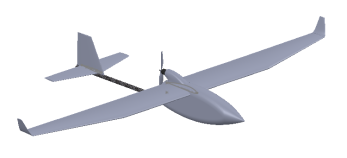
Euclid Unmanned Aerial Vehicle (UAV) is a small Unmanned Aerial Vehicle (sUAV), part of the overall Euclid UAS. The system is designed to perform security, surveillance, and reconnaissance missions. Some basic characteristics of the sUAV are presented in the following Table 1.
Table 1. Euclid UAV basic characteristics.
|
General Characteristics |
3D Image |
Velocities (m/s) |
||||
|---|---|---|---|---|---|---|
|
Wingspan $$\bm{b}\mathbf{ }\left(\bm{m}\right)$$ |
Maximum Take Off Mass (MTOM) (kg) |
Main wing area (S) (m2) |
 |
Stall (Vs) |
Cruise (Vc) |
Max (Vmax) |
|
2 |
2 |
0.35 |
9 |
15 |
30 |
|
The primary object of study in this article is to present Euclid sUAV handling qualities evaluation through flight simulation, using Cooper-Harper Handing Qualities Rating Scale. A secondary target is to promote the proposed methodology for use in similar applications.
2. Materials and Methods
Figure 1 briefly describes the sequence that took place for the Euclid evaluators to achieve an accurate output of the vehicle’s kinematics on the computer screen.
To ensure the validity of the current (simulated) handling qualities evaluation, all prior studies performed on the aircraft must be valid too. Only using valid tools and implementing properly each study, guarantees that the final evaluators will conclude to a realistic result.
Initially, the conceptual and preliminary design of the aircraft was conducted according to the methodology described in the aviation literature (indicative references [1,2,3,4,5,6]). Where appropriate, computer software is implemented to simplify the computational process. Ally through the airfoil, wing, and various other aerodynamic parameters simulation at this stage, was XFLR5 v6.48 software.
XFLR5 is an open source, low Reynolds number software for airfoil, wing, and entire aircraft simulation. Analysis is based on Lifting Line Theory, Vortex Lattice Method, and 3D Panel Method [7]. Xfoil is the precursor software of XFLR5. Xfoil is proven to be valid since the era when Prof. Mark Drela conducted the first comparisons with wind tunnel data [8]. XFLR5 is nowadays used widely by the scientific community when studying low Reynolds numbers aerial vehicles [9,10].
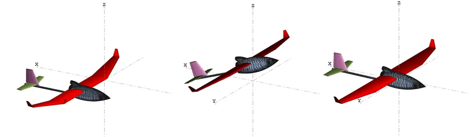
After aerodynamic and geometrical parameters of the vehicle matured, stability and control studies were carried out, using the relatively new Flow5 software v7.24.1, first released in December 2020. Flow5 is the descendant of XFLR5, and both are compatible with each other regarding the file type format. A major advantage of Flow5 compared to XFLR5 is its ability to import custom designed fuselages, in order to increase the results’ fidelity. Simulation results from various projects have already been published to the scientific community since the first year of the software’s release [11,12]. Stability derivatives, control derivatives, and a plethora of other useful parameters were extracted in this stage to be imported into the flight simulator later. Some snapshots from these studies are depicted in Figure 2.
The following Table 2, contains the major findings regarding the vehicle’s flying qualities, categorized according to [6].
Table 2. Major findings regarding Euclid sUAV flying qualities.
|
Type of Study |
Major Findings |
Flying Quality Level |
|---|---|---|
|
Short Period |
Damping ratio ζs = 0.702 |
1 |
|
Phugoid |
Damping ratio ζp = 0.01 |
2 |
|
Roll subsidence |
Roll mode time constant Tr = 0.36 |
1 |
|
Dutch Roll |
Damping ratio ζd = 0.176 |
1 |
|
Spiral |
Spiral mode time constant Τs = 12.93 |
2 |
The last step before handling the qualities evaluation was the selection of a suitable flight simulation software, with a reliable Flight Dynamics Model (FDM). Charles River RC Simulator (Crrcsim) was chosen, the Euclid 3D Computer Aided Design (CAD) model was imported, and the FDM was filled with the previously calculated parameters.
Crrcsim is a fully customizable flight simulator developed for Radio Controlled (RC) gliders, reciprocating or electric engine small aircraft. The source code is written in C & C++, under the GNU’s Not Unix (GNU) General Public License (GPL) v.2. Supported operating systems are Linux/Windows/Mac. It has been widely used in UAV research by MIT, Stanford University, UC Berkeley, and others [13].
Crrcsim uses a Langley Research Center Simulator (LaRCsim) based FDM, which is capable of simulating the flight of any vehicle moving within the atmosphere as well as above the atmosphere, up to Low Earth Orbit (LEO). Kinematic equations used are based on National Aeronautics and Space Administration (NASA) Contractor Report (CR) 2497, titled “A Standard Kinematic Model for Flight Simulation at NASA-AMES” [14].
In the year 1957, NASA engineer George Cooper presented a rating scale under the «Pilot Opinion Rating Scale» title. This scale’s objective was to evaluate the correlation between the pilot’s compensation and the handling qualities of an aerial vehicle. In 1969, engineer Robert Harper cooperated with Cooper to develop NASA’s Technical Note D-5153, regarding the scale [15]. The most recent reference on the scale can be found in [16], where the Figure 3 flowchart originates. This diagram is well known to the aviation community as the Cooper-Harper Handing Qualities Rating Scale.
The Cooper-Harper Handing Qualities Rating Scale allows pilots to correspond qualitative handling characteristics to a quantitative scale. The scale consists of numbers 1 to 10, where 1 corresponds to excellent handling qualities, while 10 corresponds to major deficiencies, where control of the vehicle will be lost during some portion of the required operation. Despite all those years in existence, Cooper-Harper Handing Qualities Rating Scale is of aviation industry’s first choice when it comes to handling qualities evaluation, as the anniversary article “Fifty Years of the Cooper-Harper Scale” [17], states.
A significant element is that Cooper-Harper Handing Qualities Rating Scale can be used for evaluating UAV’s handling qualities, both when they are naturally flying and when they are in a computer simulated flight. Also, both remotely controlled flight and autonomous flight can be evaluated using the scale [18,19]. In addition, modified Cooper-Harper Handing Qualities Rating Scales have been developed for evaluating operator’s experience with Ground Control Station (GCS) instrumentation [20,21,22]. By examining previous references, it can be stated that the flying tests that participate in the evaluation procedure vary and are not standard.

Handling qualities evaluation through computer simulation will reflect the physical aircraft’s handling qualities only if extensive aerodynamic simulation of the vehicle is performed. Each variable’s value must be computed precisely in order for the flight simulator to be able to represent the kinematics of the vehicle properly. This procedure requires a lot of human and computational resources.
Regarding the radio signal latencies that are present at remotely controlled flights, in this computer-based simulation study, we assume that the aircraft is manually controlled via a typical RC transmitter and receiver setup, and no flight controller is present in the vehicle. When commanding physical remote-controlled vehicles via full-duplex flight controller specific protocols such as MAVLink, a typical latency of 400 ms is present in the system [23]. When directly controlling such vehicles, manually, via typical simplex RC transmitters and receivers, a typical latency of 5–30 ms is to be expected [24]. This minimal delay will not affect the operator’s flying experience when flying the real vehicle at Line of Sight (LoS) short missions, compared to our results.
3. Results
In the following six subchapters and specifically at Table 3, Table 4, Table 5, Table 6, Table 7, Table 8, Table 9, Table 10, Table 11, Table 12, Table 13, Table 14, Table 15, Table 16, Table 17, Table 18, Table 19 and Table 20, the results of the evaluation of the aircraft are given. Eighteen discrete studies were conducted, segregated into the following six main categories:
-
-
Preflight Tests & Hand Launch Test
-
-
Static and dynamic stability tests
-
-
Control tests
-
-
Maneuvers
-
-
Special flight conditions
-
-
Short surveillance mission execution
All tests were carried out by three Remote Control (RC) specialists (A, B, C). All three evaluators have experience greater than 15 years in flying RC fixed wing aircraft in manual mode as well as in autonomous mode. All of them hold the European Union Aviation Safety Agency (EASA) A1/A3 drone operator license, and one of them additionally holds the A2 drone operator license. Simulation dedicated PPM (Pulse Position Modulation) controllers, as well as real RC transmitters equipped with USB dongles, were used.
For each test conducted, execution instructions and the evaluation objective were provided to the participants. As feedback, evaluators testified to their written opinion and a score for each test. Finally, a single text was synthesized containing all three evaluators’ remarks.
It is important to note that all flight responses are evaluated relative to the ideal response an aircraft of the same type would exhibit. An aerobatic RC plane certainly would have registered a higher score under the maneuvers category, but in the current case, the aircraft is compared to a vehicle designed to execute the same or a similar mission. Closest category in terms of the aeromodelling community is the First Person View (FPV) category. This category’s geometric characteristics, flying and handling qualities are similar to the Euclid UAV. All these aircrafts, are, in general, of high aspect ratio, good stability, and moderate maneuverability.
Maneuvers category, which is based on [25], is evaluated mainly by the scientific interest to perceive whether the aircraft is capable of executing them or not, in the exceptional case, it will be needed. It is, in other words, legitimate for the Euclid designer to have a handling forecast even for those extreme conditions. In the operational level, Euclid’s operators are strongly discouraged to perform such maneuvers when no emergency is present.
3.1. Preflight Tests & Hand Launch Test
In the following Table 3, the results of the control surfaces proper deflection are presented.
Table 3. Type of study: Control surfaces proper deflection.
|
Test description |
Operator deflects from $${+\bm{\delta }}_{\bm{m}\bm{a}\bm{x}}$$ to $${-\bm{\delta }}_{\bm{m}\bm{a}\bm{x}}$$, all aircraft’s control surfaces (flaps, ailerons, rudder, elevator), twice, on ground. The purpose of this test is to make sure all control surfaces are moving freely and in the correct direction. It is a necessary preflight test, and it does not participate in the final score. |
|
Result remarks |
All control surfaces are moving freely and in the correct direction. |
|
Cooper-Harper score |
First evaluator N/A, Second evaluator N/A, Third evaluator N/A |
N/A: Not Applicable.
In the following Table 4, the results of the hand launch procedure are presented.
Table 4. Type of study: Hand Launch.
|
Test description |
It is a necessary test for hand launched UAV’s, such as Euclid. A reason Crrcsim flight simulator was chosen is because its ability to simulate hand launched procedures. Three main variables must be defined for the procedure:
The main objective of this simulation is to provide evidence that the vehicle can be hand launched. Secondary targets are:
The overall hand launch procedure is evaluated, using the optimum values. |
|
Result remarks |
|
|
Cooper-Harper score |
First evaluator 1, Second evaluator 1, Third evaluator 1. |
3.2. Static & Dynamic Stability Tests
In the following Table 5, the results of the short period are presented.
Table 5. Type of study: Longitudinal static stability & Dynamic stability: Short Period (Pitch movement).
|
Test description |
A simultaneous simulation regarding aircraft’s longitudinal static stability and its short period response, is performed. During Straight and Level Flight (SLF), the operator temporarily cuts off the engine power, so the generated force from it, not to affect the progress of the phenomena. Afterwards, the operator deflects shortly and quickly the aileron at $$-{\bm{\delta }}_{{\bm{e}}_{\bm{m}\bm{a}\bm{x}}}$$ in order to for positive pitching moment (+Μ) to be produced, for the perturbation to appear. The object of research here is to evaluate the aircraft’s reinstatement to SLF. |
|
Result remarks |
Aircraft is longitudinally dynamically (therefore and statically), stable. The phenomenon is evolving absolutely satisfactory. |
|
Cooper-Harper score |
First evaluator 1, Second evaluator 1, Third evaluator 1. |
In the following Table 6, the results of the Dutch roll movement are presented.
Table 6. Type of study: Static stability (Directional & Lateral) & Dynamic stability: Dutch Roll (Yaw & Roll movements).
|
Test description |
A simultaneous simulation regarding aircraft’s directional & lateral static stability is performed. The flight behavior of both is dynamically reflected through the Dutch Roll output. During Straight and Level Flight (SLF), the operator deflects shortly and quickly the rudder at $$-{\bm{\delta }}_{{\bm{r}}_{\bm{m}\bm{a}\bm{x}}}$$, in order to for negative yawing moment $$\left(-\bm{N}\right)\bm{ }$$to be produced, for the perturbation to appear. For achieving the best results, it is important that the rudder stick returns to its neutral position as fast as possible. The optimum way to achieve this is to simply release the rudder stick and let it return using only the tension of the spring supporting it. The object of research here is to evaluate how well the Dutch Roll movement is damped. |
|
Result remarks |
Dutch Roll outputs a healthy damping ratio. |
|
Cooper-Harper score |
First evaluator 1, Second evaluator 2, Third evaluator 1. |
3.3. Control Tests
In the following Table 7, the results of the elevator deflection are presented.
Table 7. Type of study: Elevator deflection (Pitch movement).
|
Test description |
Aircraft launches and after it gains safe altitude, it implements two sequential ascends and descents, deflecting the elevator only. In a well-trimmed aircraft only pithing angle θ should alter and none of φ & y angles, indicating that the aircraft’s Center of Gravity (CG) is in symmetry with $$\left(\bm{O}{\bm{x}}_{\bm{s}}{\bm{z}}_{\bm{s}}\right)$$ plane of stability axes. The object here is to evaluate if only θ angle is altered and the handling quality of the movement. |
|
Result remarks |
Only θ angle is altered, and the pitch handling is absolutely satisfactory. |
|
Cooper-Harper score |
First evaluator 1, Second evaluator 1, Third evaluator 1. |
In the following Table 8, the results of the ailerons deflection are presented.
Table 8. Type of study: Ailerons deflection (Roll movement).
|
Test description |
The aircraft launches, and after it gains safe altitude, it implements three indicative small bank turns using only the ailerons. The expected behavior and subject of evaluation should be mainly a variation in the roll angle (φ) and secondarily a smaller variation in pitch angle (ψ), because the UAV is designed with $${\mathbf{ }\mathbf{C}}_{{\bm{n}}_{{\bm{\delta }}_{\bm{a}}}\mathbf{ }}$$ > 0. |
|
Result remarks |
When deflecting ailerons, the aircraft is behaving exactly as expected. |
|
Cooper-Harper score |
First evaluator 1, Second evaluator 1, Third evaluator 1. |
In the following Table 9, the results of the rudder deflection are presented.
Table 9. Type of study: Rudder deflection (Yaw movement).
|
Test description |
Aircraft launches and after it gains a safe altitude, only the rudder is deflected. The expected behavior and subject of evaluation should be mainly a variation in pitch angle (ψ) and secondarily a smaller variation in roll angle (φ), because the UAV is designed with $${\mathbf{C}}_{{\bm{l}}_{{\bm{\delta }}_{\bm{r}}}}$$ > 0. |
|
Result remarks |
When deflecting the rudder, the aircraft is behaving exactly as expected. |
|
Cooper-Harper score |
First evaluator 1, Second evaluator 1, Third evaluator 1. |
3.4. Flight Maneuvers
For maneuvers schematics see [25]. In the following Table 10, the results of the loop maneuver are presented.
Table 10. Type of study: Loop.
|
Test description |
While in SLF, the circular trajectory loop maneuver is executed with max thrust during ascent. The objective here is to investigate if the produced thrust is capable of executing the maneuver, and the pilot’s comfort while executing the maneuver, for the given type of aircraft. |
|
Result remarks: |
The aircraft is capable of executing the loop maneuver with adequate pilot comfort. |
|
Cooper-Harper score |
First evaluator 2, Second evaluator 1, Third evaluator 1. |
In the following Table 11, the results of the roll maneuver are presented.
Table 11. Type of study: Roll.
|
Test description |
While in SLF, a full 360° rotation is performed around the x axis, deflecting only the ailerons. Objective here is for the UAV to return to its initial position, with acceptable altitude loss. |
|
Result remarks |
Aircraft is capable of executing the roll maneuver with adequate pilot comfort and acceptable altitude loss. |
|
Cooper-Harper score |
First evaluator 2, Second evaluator 1, Third evaluator 2. |
In the following Table 12, the results of the inverted flight maneuver are presented.
Table 12. Type of study: Inverted Flight.
|
Test description |
While in SLF, a 180° rotation is performed around the x-axis, and the UAV remains in this inverted position for 10 s. The objective here is to investigate if the aircraft is capable of sustaining inverted flight according to the CL_min variable’s value calculated and imported to the flight simulator FDM. If the aircraft can execute inverted flight, the minimum throttle (%) should be recorded for sustaining this flight condition. |
|
Result remarks |
The aircraft is capable of flying inverted with a minimum throttle of 75%. |
|
Cooper-Harper score |
First evaluator 1, Second evaluator 1, Third evaluator 1. |
In the following Table 13, the results of the Immelmann maneuver are presented.
Table 13. Type of study: Immelmann.
|
Test description |
While in SLF, the aircraft performs the Immelmann maneuver with full throttle during ascent. If the aircraft can execute the loop maneuver, it should be able to execute the Immelmann maneuver as well. The object here is to evaluate the pilot’s comfort while executing the maneuver. |
|
Result remarks |
The aircraft is capable of executing the Immelmann maneuver with adequate pilot comfort. |
|
Cooper-Harper score |
First evaluator 2, Second evaluator 2, Third evaluator 2. |
In the following Table 14, the results of the Split-S maneuver are presented.
Table 14. Type of study: Split-S.
|
Test description |
Split-S is a reverse trajectory maneuver of Immelmann’s. The main difference between the two is that Split-S does not require great thrust forces by the engine, because it takes advantage of the potential energy the aircraft has gained due to altitude. The object here is to evaluate the pilot’s comfort while executing the maneuver. |
|
Result remarks |
The aircraft is capable of executing the Split-S maneuver with adequate pilot comfort. |
|
Cooper-Harper score |
First evaluator 1, Second evaluator 1, Third evaluator 1. |
3.5. Special Flight Conditions Tests
In the following Table 15, the results of the stall recovery maneuver are presented.
Table 15. Type of study: Stall Recovery.
|
Test description |
While flying at a safe altitude, the engine power is cut off and the aircraft is let to glide for a short distance in order to reduce airspeed. Afterwards, the operator implements an elevator up command, for the remaining lift force to be destroyed completely and to put the aircraft in a stall condition. Operator’s opinion is recorded regarding the easiness of exiting form this condition. |
|
Result remarks |
Stall recovery can be executed with varying ease among the evaluators, but is fairly easy for the aircraft’s type and given mass. To exit the stall with this aircraft, all operators aggraded that first a nose down and then a throttle increase should be implemented. |
|
Cooper-Harper score |
First evaluator 2, Second evaluator 3, Third evaluator 1. |
In the following Table 16, the results of the High Angle of Attack (High AoA) maneuver are presented.
Table 16. Type of study: High Angle of Attack (High AoA).
|
Test description |
Flying at a high AoA, or high alpha, is a dynamically complex and volatile aerodynamic condition, where an aircraft flies at a high angle of attack, for an adequate time, in the borderline between the stall region and the normal controlled flight, without losing altitude [26]. For replicating this flight condition in the flight simulator, the operator must follow the same steps as the previous test 11 until the elevator up command, which should be maintained throughout the whole duration of the maneuver. At the same time, the operator must regulate the aircraft’s thrust accordingly, in order to maintain the evolution of the maneuver, even when φ & ψ angles are changing. High AoA is a test of great importance, because it can evince whether the lift distribution upon the wing is in truth elliptical as designed, and the wingtips will not suffer a stall before the wing root, resulting in aileron ineffectiveness and lost of control.When executed in the flight simulator, high AoA is better performed near the ground so the evaluator has a better perspective on possible altitude loss. |
|
Result remarks |
High AoA flight conditions can be performed safely. Aircraft is fully controllable, even when φ & ψ angles are changing. |
|
Cooper-Harper score |
First evaluator 1, Second evaluator 1, Third evaluator 1. |
In the following Table 17, the results of the Spin Recovery (SR) maneuver are presented.
Table 17. Type of study: Spin Recovery (SR).
|
Test description |
According to Sadraey [3], spin is a dangerous and continuous rotation of an aircraft around its z axis, which may occur after a stall. Aircraft suffers altitude loss with Rate of Descent (ROD) equal to 20–100 m/s and a Rate of Spin (Ω) equal to 20–40 rpm. Along with its axial rotation, it writes off a helicoid trajectory in space, with a radius equal to its semispan (R = b/2). Every aircraft type demonstrates a different behavior regarding spin. Usually, prone to spin are fighters and aerobatic aircrafts. The very opposite behavior have a lot of transport aircrafts, which are designed to exit the spin easily using big rudders (spin proof), or even being immune to spin (unspinnable). A beneficial contribution to avoid, or to easily exit a spin, has the proper mass distribution within the aircraft itself, which affects the aircraft’s moments of inertia. Official Federal Aviation Administration (FAA-H-8083-3C) textbook [27] describes exactly the procedures that must be followed by a pilot to willfully enter into a spin and to exit from it as well. In brief, to enter a spin after a stall, the pilot must deflect the rudder by $${\bm{\delta }}_{\bm{m}\bm{a}\bm{x}}$$ and to exit from the spin a $${\bm{\delta }}_{\bm{m}\bm{a}\bm{x}}$$ rudder of opposite direction must be applied. For the current simulated spin test, the UAV operator is encouraged to follow the aforementioned procedure to record whether the UAV can enter a spin and, if so, to evaluate the ease of the exit attempt from it. |
|
Result remarks |
After multiple attempts to put the UAV into a spin, no one among the three evaluators succeeded to spin the aircraft. |
|
Cooper-Harper score |
First evaluator 1, Second evaluator 1, Third evaluator 1. |
In the following Table 18, the results of the glide maneuver are presented.
Table 18. Type of study: Glide.
|
Test description |
It concerns of a simple glide test, which aims to visually demonstrate in the computer screen, the CL/CD glide ratio of the UAV, which was found to be equal to 22.3 during Euclid’s aerodynamic simulations. The current test is performed from a high altitude, with a disabled engine. Projected to earth travel distance, ability of controlling the UAV, and easiness of landing are evaluated. |
|
Result remarks |
The UAV is able to glide with ease, covering a safe distance upon its landing. During the glide test, evaluators agreed that the aircraft is well controlled as long as small and smooth inputs are given to it from the controller. |
|
Cooper-Harper score |
First evaluator 2, Second evaluator 1, Third evaluator 2. |
In the following Table 19, the results of the flaps usage are presented.
Table 19. Type of study: Flaps usage.
|
Test description |
This test assesses the flaps effectiveness during descent and landing. Flaps usage is evaluated regarding its ability to lead to a safer and of a short distance and speed, approach, and landing. |
|
Result remarks |
Using flaps, the aircraft can land more safely. Approach and landing distances and speeds are shortened. |
|
Cooper-Harper score |
First evaluator 1, Second evaluator 1, Third evaluator 1. |
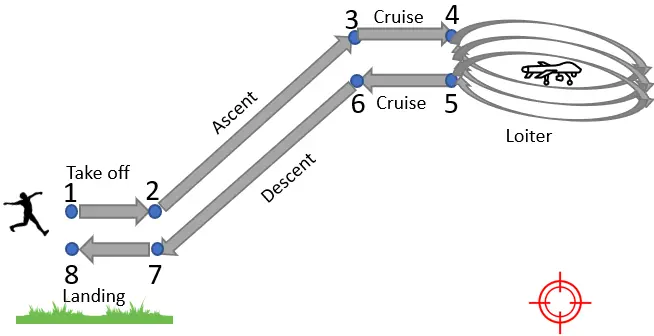
3.6. A Typical Short Surveillance Mission Test
In the following Table 20, the results of the typical short surveillance mission test are presented.
Table 20. A typical short surveillance mission test.
| Short Surveillance Mission Execution | |||||
|---|---|---|---|---|---|
| Type of Study | Test Description | Result Remarks | Cooper-Harper Score | ||
| Flight Phases | |||||
| 1→2: Take off | Using hand haunch method. | This short surveillance mission was carried out without any problems within ~2 min. | Α | Β | C |
| 2→3: Ascent | Full throttle, up to cruising altitude | 1 | 2 | 1 | |
| 3→4: Cruise towards target | For a short time at Vc. | ||||
| 4→5: Loiter | Three cycles of execution, above the hypothetical target. | ||||
| 5→6: Cruise towards landing field | For a short time at Vc. | ||||
| 6→7: Descent | Using 20% throttle and max flaps. | ||||
| 7→8: Landing | Belly landing, within the flight simulator’s available landing field. | ||||
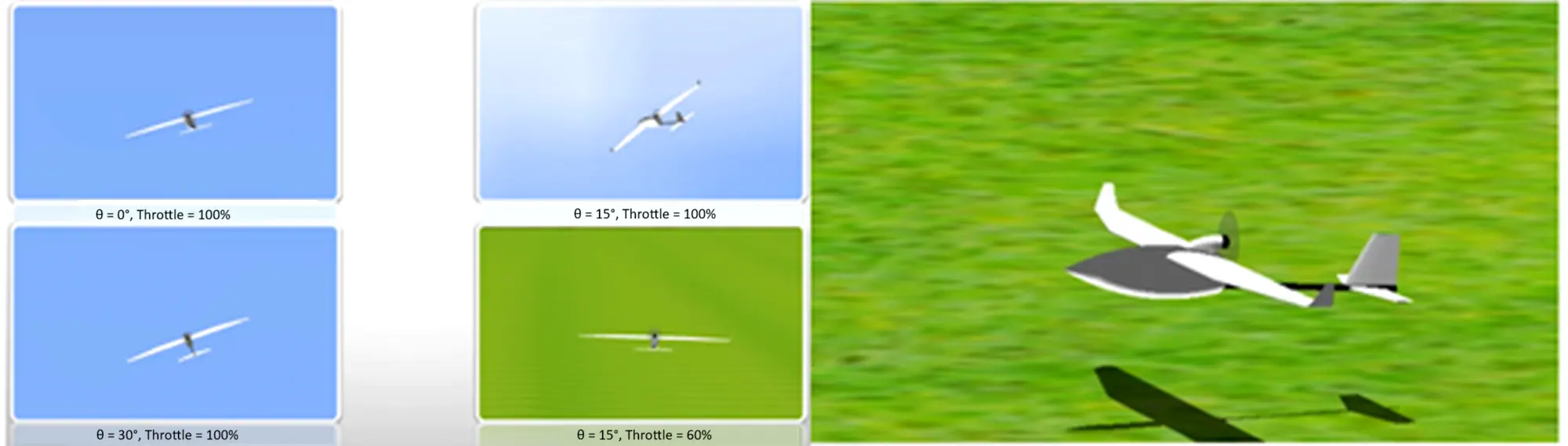
The following Figure 4 depicts the short surveillance mission’s flight phases.
The following Figure 5 contains some screenshots from the Euclid flight simulations.
A video of the whole process with a duration of seven minutes can be viewed in the link provided in the Supplementary Materials named “Video S1”.
4. Discusion
Evaluating handling qualities, via simulation, with Cooper-Harper Handing Qualities Rating Scale, is an easy but important procedure, which can foresee various aircraft defects, prior to its physical maiden flight. For an accurate model motion in the flight simulator, it is essential that all prior aerodynamic studies be conducted carefully, using valid tools. The 18-step proposed novel methodology covers adequately all possible flight conditions a Small fixed wing UAV will face when executing security, surveillance, reconnaissance, or similar missions. This work can be used as is, by users who want to evaluate their fixed wing vehicle’s handling qualities in manual modes of flight. We will also be very happy if any research team expands our work. Directions for further experimental research could contain adding autonomous modes of flight and/or Vertical Take Off and Landing (VTOL) capabilities.
5. Conclusions
Specific conclusions from Euclid sUAV handling qualities evaluation are the following:
-
-
All Cooper-Harper scores fluctuated in (1–3) span. This fact is translated as satisfactory, without improvement, handling qualities.
-
-
Some tests evaluated with scores 2 or 3 are possibly related to UAV’s given mass for the simulation, as all three evaluators generally agreed. In further simulations conducted in those tests with a 200 g reduced vehicle mass, handling qualities seemed to be improved. This remark constitutes a strong motivation for the continuous effort of mass reduction during the construction phase.
-
-
All flight maneuvers executed successfully.
Supplementary Materials
The following supporting information can be found at: https://www.sciepublish.com/article/pii/885, Video S1: The process of evaluating the Euclid UAV using the proposed methodology.
Author Contributions
Conceptualization, I.K.K.; Methodology, I.K.K.; Software, I.K.K.; Validation, I.K.S.; Formal Analysis, I.K.S.; Investigation, I.K.S.; Resources, I.K.K.; Data Curation, I.K.K.; Writing—Original Draft Preparation, I.K.K.; Writing—Review & Editing, I.K.S.; Visualization, I.K.K.; Supervision, I.K.S.; Project Administration, I.K.S.
Ethics Statement
Not applicable.
Informed Consent Statement
Not applicable.
Data Availability Statement
Research data is available by request to the corresponding author.
Funding
This research received no external funding.
Declaration of Competing Interest
The authors declare that they have no known competing financial interests or personal relationships that could have appeared to influence the work reported in this paper.
References
-
Raymer DP. Aircraft Design: A Conceptual Approach; In AIAA education series; American Institute of Aeronautics and Astronautics, Inc.: Reston, VA, USA, 2018. [Google Scholar]
-
Sadraey MH. Design of Unmanned Aerial Systems; In Aerospace series; John Wiley & Sons: Hoboken, NJ, USA, 2020. [Google Scholar]
-
Sadraey MH. Aircraft Design: A Systems Engineering Approach; In Aerospace series; Wiley: Chichestet, UK, 2013. [Google Scholar]
-
Gudmundsson S. General Aviation Aircraft Design: Applied Methods and Procedures, 1st ed.; Butterworth-Heinemann: Oxford, UK; Waltham, MA, USA, 2014. [Google Scholar]
-
Kundu AK. Aircraft Design; Cambridge University Press: Cambridge, UK; New York, NY, USA, 2010. [Google Scholar]
-
Cook MV. Flight Dynamics Principles: A Linear Systems Approach to Aircraft Stability and Control, 3rd ed.; In Elsevier aerospace engineering series; Butterworth-Heinemann: Amsterdam, The Netherlands; Boston, MA, USA, 2013. [Google Scholar]
-
Deperrois A. XFLR5 Analysis of Foils and Wings Operating at Low Reynolds Numbers. 2009. Available online: https://www.researchgate.net/profile/Mohamed-Mourad-Lafifi/post/Bravo_UAV_half_scale_trainer_analysis/attachment/5feb27c23b21a200016534c5/AS%3A974065238032385%401609246658631/download/XFLR5+Analysis+of+foils+and+wings+operating+at+low+Reynolds+numbers.pdf (accessed on 27 February 2026).
-
Drela M. XFOIL: An Analysis and Design System for Low Reynolds Number Airfoils; Springer: Berlin/Heidelberg, Germany, 1989; pp. 1–12. [Google Scholar]
-
Shams TA, Shah SIA, Javed A, Hamdani SHR. Airfoil Selection Procedure, Wind Tunnel Experimentation and Implementation of 6DOF Modeling on a Flying Wing Micro Aerial Vehicle. Micromachines 2020, 11, 553. DOI:10.3390/mi11060553 [Google Scholar]
-
Morgado J, Vizinho R, Silvestre MAR, Páscoa JC. XFOIL vs. CFD performance predictions for high lift low Reynolds number airfoils. Aerosp. Sci. Technol. 2016, 52, 207–214. DOI:10.1016/j.ast.2016.02.031 [Google Scholar]
-
Lelkov KS, Ulyanov DV, Surkov DA, Ushakov AN. Development of the mathematical model for the tilt-rotor aircraft. J. Phys. Conf. Ser. 2021, 1925, 012041. DOI:10.1088/1742-6596/1925/1/012041 [Google Scholar]
-
Klein V, Skultety F, Cernan J. Aerobatic Trainer Aircraft Conceptual Design. In 2021 New Trends in Aviation Development (NTAD); IEEE: Košice, Slovakia, 2021; pp. 91–96. DOI:10.1109/NTAD54074.2021.9746506 [Google Scholar]
-
Thibault C, Nagaty A, Seto M, Trentini M, Li H. Construction, Modeling and Control of an Autonomous Unmanned Aerial Vehicle Testbed. Defence Research and Development Canada—Atlantic, Dartmouth, Nova Scotia B2Y 3Z7, DRDC Atlantic SL 2011-125, Jan 2013. Available online: https://cradpdf.drdc-rddc.gc.ca/PDFS/unc381/p814170_A1b.pdf (accessed on 24 May 2022).
-
McFarland R. A Standard Kinematic Model for Flight Simulation at NASA-AMES. National Aeronautics and Space Administration, Mountain View, Calif., Contractor Report NASA CR-2497, Jan 1975. Available online: https://ntrs.nasa.gov/citations/19750006408 (accessed on 29 May 2022).
-
Cooper G, Harper R. The Use of Pilot Rating in the Evaluation of Aircraft Handling Qualities. National Aeronautics and Space Administration, Washington, DC, Technical Note NASA TN D-5153, 1969. Available online: https://ntrs.nasa.gov/citations/19690013177 (accessed on 26 May 2022).
-
Harper R, Jr., Cooper G. Wright Brothers Lectureship in Aeronautics—Handling qualities and pilot evaluation. In Aircraft Design Systems and Operations Meeting; American Institute of Aeronautics and Astronautics: San Diego, CA, USA, 1984. DOI:10.2514/6.1984-2442 [Google Scholar]
-
Mitchell DG. Fifty Years of the Cooper-Harper Scale. In AIAA Scitech 2019 Forum; American Institute of Aeronautics and Astronautics: San Diego, CA, USA, 2019. DOI:10.2514/6.2019-0563 [Google Scholar]
-
González P, Boschetti P, Cárdenas E, Amerio A. Evaluation of the Flying Qualities of a Half-Scale Unmanned Airplane via Flight Simulation. In 48th AIAA Aerospace Sciences Meeting Including the New Horizons Forum and Aerospace Exposition; American Institute of Aeronautics and Astronautics: Orlando, FL, USA, 2010. DOI:10.2514/6.2010-298 [Google Scholar]
-
Kopyt A, Żugaj M. Analysis of Pilot Interaction with the Control Adapting System for UAV. J. Aerosp. Eng. 2020, 33, 04020025. DOI:10.1061/(ASCE)AS.1943-5525.0001109 [Google Scholar]
-
Donmez B, Cummings ML, Graham HD, Brzezinski AS. Modified Cooper Harper scales for assessing unmanned vehicle displays. In Proceedings of the 10th Performance Metrics for Intelligent Systems Workshop; ACM: Baltimore, MD, USA, 2010; pp. 235–242. DOI:10.1145/2377576.2377620 [Google Scholar]
-
Cotting MC. UAV Performance Rating Scale Based on the Cooper-Harper Piloted Rating Scale. In 49th AIAA Aerospace Sciences Meeting including the New Horizons Forum and Aerospace Exposition; American Institute of Aeronautics and Astronautics: Orlando, FL, USA, 2011. DOI:10.2514/6.2011-923 [Google Scholar]
-
González P, Boschetti P, Cardenas E, Carrero M. Evaluation of the Flying Qualities of a Light Unmanned Airplane via Flight Simulation. In 50th AIAA Aerospace Sciences Meeting including the New Horizons Forum and Aerospace Exposition; American Institute of Aeronautics and Astronautics: Nashville, TN, USA, 2012. DOI:10.2514/6.2012-853 [Google Scholar]
-
Aziz F, Loya A. Multi-Mode MAVLink Test Bench AeroQT for Aircraft Simulation and Real-Flight Validation. Aerosp. Res. Commun. 2025, 3, 14524. DOI:10.3389/arc.2025.14524 [Google Scholar]
-
Mohamed MAM, Oniz Y. Real-Time Long-Range Control of an Autonomous UAV Using 4G LTE Network. Drones 2025, 9, 812. DOI:10.3390/drones9120812 [Google Scholar]
-
Roessingh JJM. Transfer of Manual Flying Skills From PC-Based Simulation to Actual Flight-Comparison of In-Flight Measured Data and Instructor Ratings. Int. J. Aviat. Psychol. 2005, 15, 67–90. DOI:10.1207/s15327108ijap1501_4 [Google Scholar]
-
Wu D, Sun Y, Yan X. Adaptive neural tracking control for high angle of attack maneuver with average dwell time. Int. J. Adapt. Control Signal Process. 2021, 35, 2446–2465. DOI:10.1002/acs.3331 [Google Scholar]
-
FAA. Airplane Flying Handbook: FAA-H-8083-3C; Aviation Supplies & Academics, Inc.: Newcastle, WA, USA, 2021. [Google Scholar]