Fabrication, Properties of Dense CA6 Refractory and Its Reaction Behavior with Titanium Aluminum Alloy

Fabrication, Properties of Dense CA6 Refractory and Its Reaction Behavior with Titanium Aluminum Alloy
Suzhen Han 1,2 Lvping Fu 1,2,3,*,† Changmao Peng 1,2 Ning Liu 1,2 Huazhi Gu 1,2 Jiuxi Zhou 3 Ao Huang 1,2
Received: 22 September 2025 Revised: 30 October 2025 Accepted: 19 December 2025 Published: 30 December 2025

© 2025 The authors. This is an open access article under the Creative Commons Attribution 4.0 International License (https://creativecommons.org/licenses/by/4.0/).
1. Introduction
Titanium aluminum (TiAl) alloys are characterized by their low density, high specific strength and stiffness, excellent corrosion resistance, and remarkable heat and radiation resistance [1,2,3,4,5,6,7,8]. These properties make them highly promising for aerospace applications, particularly in the manufacturing of engine blades, aircraft, and missile components that must endure high-temperature and high-pressure environments. As a result, the melting and processing of TiAl alloys have become a key research focus in the field of superalloys [9,10].
Currently, there are three primary methods for melting titanium alloy: vacuum arc melting (VAR), cold hearth furnace melting (CHM), and vacuum induction melting (VIM). Among these, vacuum induction melting technology offers significant advantages in terms of energy efficiency and production costs. However, a major challenge in the production and application of vacuum induction melting for titanium alloys is the lack of crucible materials with sufficient stability [11]. Consequently, identifying a suitable crucible material is a critical prerequisite for achieving the industrial-scale production of titanium alloys using vacuum induction melting.
Due to the high chemical reactivity of TiAl alloys at elevated temperatures, they tend to react with nearly all known refractory materials. As a result, refractory materials used for melting TiAl alloys must possess adequate mechanical strength, excellent corrosion resistance, and strong thermal shock resistance.
Scholars worldwide have conducted extensive research on crucible materials for the induction melting of TiAl alloys. Commonly studied oxide crucible materials include Al2O3, ZrO2, CaO, Y2O3, etc. [12,13,14,15,16]. Zhang H et al. [17] investigated the interfacial reaction between an Al2O3 crucible and a TiAl alloy melt under varying directional solidification temperatures and holding times. The formation of a distinct reaction layer (TiO) was observed at the interface, the thickness of which increased with both temperature and holding time. Zhu J et al. [18] studied the interfacial behaviour between Y2O3-stabilised ZrO2 crucibles and titanium alloys, demonstrating that Y2O3-stabilised ZrO2 possesses superior stability compared to CaO-stabilised ZrO2, although its erosion resistance remains lower than that of pure Y2O3 crucibles. Consequently, ZrO2-based materials are not considered suitable for industrial-scale mass production. Fu B et al. [19] examined the interface reaction between CaO crucibles and Ti-1100 alloy. Their results indicated that CaO crucibles increase the oxygen content in titanium-aluminium alloys during melting. Moreover, CaO is prone to hydration and difficult to sinter, further limiting its industrial applicability. Tetsui T et al. [20] employed yttrium as a crucible material for the induction melting of TiAl alloys, observing the detachment of crucible material into the final alloy and poor thermal shock resistance. Research findings indicate that Al2O3 and ZrO2 crucibles undergo severe interfacial reactions with TiAl alloy melts, resulting in alloy contamination. While CaO and Y2O3 exhibit better thermodynamic stability, CaO is prone to hydration and difficult to sinter, limiting its industrial applicability [17,18,19]. Similarly, Y2O3 suffers from poor thermal shock resistance and can dissolve into the alloy melt, forming inclusions that significantly degrade the alloy’s performance [20].
CA6, the calcium aluminate phase with the highest alumina content in the Al2O3-CaO system, exhibits excellent hydration resistance, corrosion resistance, low thermal conductivity, and superior mechanical properties. These characteristics have garnered significant attention in recent years [21,22,23,24]. However, its application in the field of TiAl alloy smelting has yet to be explored. Qi et al. [25] proposed the preparation of a CaO-Al2O3-TiO2 crucible and found that the crucibles with lower TiO2 content demonstrated good resistance to penetration and erosion by titanium-aluminum alloys. In contrast, pure CaO-Al2O3 crucibles showed minimal erosion but severe penetration issues. This indicates that while CA6 exhibits excellent chemical stability, its low density leads to significant penetration problems.
Therefore, a dense CA6 crucible refractory was prepared using a two-step sintering method for smelting Ti6Al4V alloy. The reaction behavior of CA6 crucible refractory with different phases and Ti6Al4V alloy was investigated to develop a material with exceptional chemical stability and thermal shock resistance for titanium-aluminum alloy smelting.
2. Materials and Methods
2.1. Starting Materials
The main raw materials in this study are: industrial Al2O3 powder (median particle size: 4–5 μm, purity ≥ 99%, Jiangsu Jingxin New Materials Co., Ltd., Yangzhou, China), nano-CaCO3 (median particle size: 60–80 nm, purity ≥ 96%, Zhejiang Changshan Jinxiong Co., Ltd., Quzhou, China), and TiO2 (median particle size: ~10 μm, purity ≥ 99%, Shanghai McLean Biochemical Technology Co., Ltd., Shanghai, China).
2.2. Sample Preparation
CA6 refractory was synthesized using industrial Al2O3 and CaCO3 as raw materials and TiO2 as a sintering aid. The raw materials were weighed according to the experimental formula in Table 1, and placed into a ball mill tank. The mixture was dry-ground in a planetary ball mill for 40 min at a rotation speed of 258 rpm, with a powder-to-ball mass ratio of 1:6. The ball-milled powder was then naturally stacked in an alumina crucible and pre-sintered in a medium-temperature furnace at 1300 °C for 3 h under an air atmosphere. After pre-sintering, 1% TiO2 sintering aid was added to the powder, followed by an additional 3 h of grinding in the planetary ball mill. Subsequently, 1 wt% polyvinyl alcohol (PVA) solution (10 wt% concentration) was added as a binder and mixed thoroughly. The mixture was then pressed into various shapes using a hydraulic press at 150 MPa, including cylindrical billets (Φ 20 mm × 20 mm), strip billets (50 mm × 10 mm × 10 mm and 100 mm × 15 mm × 15 mm), and crucible samples (Φ 50 mm × 50 mm with an inner diameter of Φ (12~15) mm × 15 mm). The green bodies were dried in a vacuum oven at 80 °C and 110 °C for 24 h each. Finally, the samples were heat-treated in a high-temperature sintering furnace at 1750 °C for 3 h under an air atmosphere.
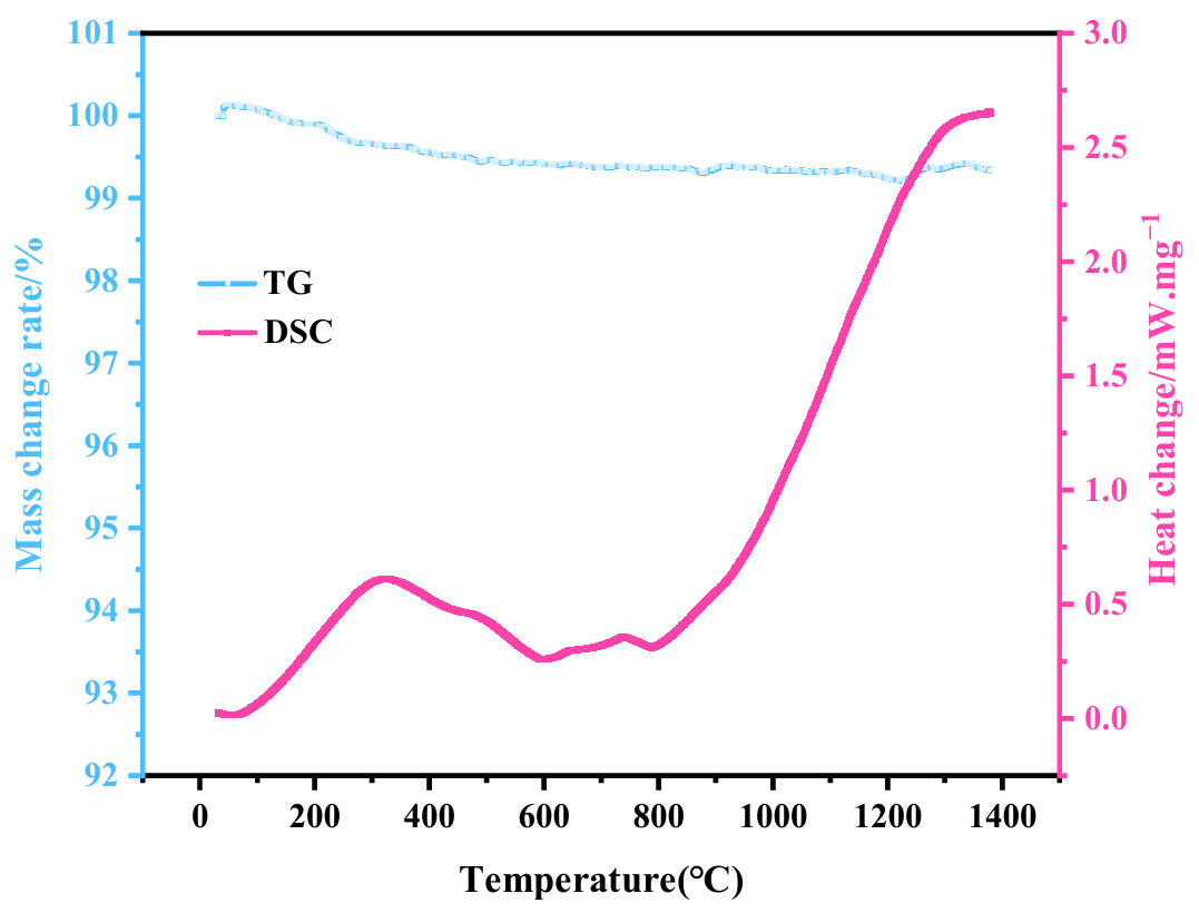
In order to understand the phase transformation pathway of CA6 during sintering, Figure 1 presents the TG-DSC curves obtained during thermal treatment. The data reveal that after pre-sintering at 1300 °C, the TG curve shows virtually no weight loss, with the low-temperature endothermic peak entirely eliminated. The predominant crystalline phases are calcium aluminate (CaAl4O7, CA2) and α-Al2O3, indicating that the system has undergone extensive removal of volatile components and has formed a thermodynamically stable intermediate-phase framework. The powder subjected to 1300 °C pre-sintering is thus in a fully reacted state.
Table 1. Composition of raw materials for sample preparation (wt%).
|
Raw Materials |
Samples |
||
|---|---|---|---|
|
Al2O3 |
Al2O3-CA6 |
CA6 |
|
|
Industrial Al2O3 |
100 |
88 |
85.94 |
|
CaCO3 |
- |
12 |
14.06 |
|
TiO2 |
- |
+1 |
+1 |
2.3. Test and Characterizations
The phase composition of the samples was analyzed using an X-ray diffraction (X′ pert pro, PANalytical, Almelo, The Netherlands). The microstructure and element distribution of the samples were analyzed by a field emission scanning electron microscope field emission equipped with backscattered electron imaging(SEM, FEI Nova 400 Nano-SEM, FEI, Portland, OR, USA) and an X-ray energy-dispersive spectrometer (INCA Penta FET-X3, Oxford Instruments, Oxford, UK).
The dimensions of the samples before and after sintering were measured using a vernier caliper to calculate the linear shrinkage rate. Bulk density and apparent porosity were determined using the Archimedes method. Thermal diffusivity and specific heat capacity were measured from room temperature to various elevated temperatures using an laser thermal conductivity meter (LFA 457 MicroFlash, NETZSCH-Gerätebau GmbH, Selb, Germany). Thermal conductivity was calculated based on the sample’s volumetric density. The coefficient of thermal expansion from room temperature to 1400 °C was measured using a high-temperature thermal dilatometer (DIL502, NETZSCH-Gerätebau GmbH, Selb, Germany) at a heating rate of 10 °C/min.
The bending strength of specimens (50 mm × 10 mm × 10 mm) was evaluated using the three-point bending method. A constant load of 0.5 MPa/s was applied vertically until fracture, and the maximum load Fmax(N) was recorded. This quasi-static loading regime ensured that material deformation and failure took place under near-static conditions, thereby accurately capturing the flexural strength behavior of the material. For thermal shock resistance testing, samples were heated in an electric furnace at 1100 °C for 20 min, then rapidly quenched in flowing water at 5–35 °C for 3 min. The residual bending strength was measured to assess thermal shock resistance.
The alloy melting experiment was conducted using a VIF-2 vacuum induction melting furnace. Ti6Al4V alloy was used for the experiment. The self-made crucible containing the alloy was placed inside a graphite crucible, which was then positioned within a quartz crucible. After sealing the furnace, the chamber was evacuated to 1 × 10⁻² Pa using a mechanical pump and a molecular pump. Argon gas was introduced to achieve a pressure of 0.06 MPa, and the system was purged three times with low-vacuum gas. The heating power was then activated to initiate the melting process. The temperature of the alloy melt was monitored using a tungsten-rhenium thermocouple, and the alloy was heated to 1700 °C within 90 min. After melting, the alloy was held in an argon atmosphere for 3 min. The power supply was subsequently turned off, and the melt was allowed to cool in the furnace before removal for further analysis.
3. Results and Discussion
3.1. Phase Composition and Microstructure
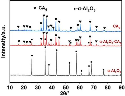
In order to clarify the reaction behavior of the CA6 crucible and Ti6Al4V alloy, three groups of crucible materials with varying phase compositions were prepared. Figure 2 shows the XRD patterns of the three groups of samples after heat treatment at 1750 °C. The results indicate that the phases present in the samples are Al2O3, Al2O3-CA6, and CA6, corresponding to the three groups of refractories. It is evident that the CA6 phase formed through a high-temperature solid-state reaction between CaCO3 and Al2O3. When the mass ratio of CaCO3 to Al2O3 was less than 1:6, the material contained both the CA6 phase and residual Al2O3 phase. In contrast, when the mass ratio of CaCO3 to Al2O3 was 1:6, the material exhibited a single CA6 phase. Although the single-phase CA6 sample was prepared with CaCO3 and Al2O3 in stoichiometric proportions, a trace amount of Al2O3 was still detected in the XRD pattern. This discrepancy may be attributed to uneven local dispersion of the mixture during dry mixing, leading to incomplete reaction.
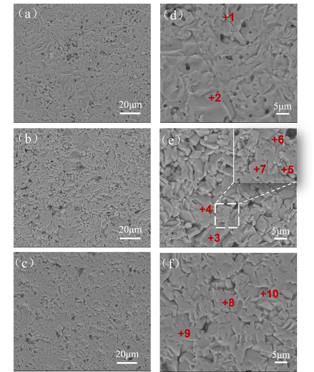
The SEM images and EDS spectra of the three groups of samples with different phases are presented in Figure 3 and Table 2. In the Al2O3 sample (Figure 3d), the grains are tightly bonded with minimal porosity, and only a small amount of pores are distributed between the grains. With the addition of CaCO3 and the corresponding decrease in Al2O3 content, the microstructure shows an increase in flake-like grains arranged in an interlocking network. When the mass ratio of CaCO3 to Al2O3 is less than 1:6, the sample exhibits higher porosity with larger size, along with relatively complete grains. The CA6 phase (points 4 and 7) forms a distinct interlocking lamellar structure, while the Al2O3 phase (points 3, 5, and 6) is present at grain boundaries, where the grains are more densely bonded. When the mass ratio of CaCO3 to Al2O3 is equal to 1:6, a significant amount of CA6 crystals is observed in the sample (Figure 3f). Compared to the Al2O3-CA6 sample, the lamellar structure of the crystal is less pronounced, and the grains exhibit a “bridging” morphology with an interwoven arrangement. The crystals tend to develop into an equiaxed shape, and the pore distribution becomes more uniform.
Table 2. EDS results of Figure 2 (at %).
|
Points |
Ca |
Al |
O |
Ti |
Possible Phases |
|---|---|---|---|---|---|
|
1 |
- |
45.62 |
54.38 |
- |
Al2O3 |
|
2 |
- |
43.86 |
56.14 |
- |
Al2O3 |
|
3 |
- |
46.54 |
53.46 |
- |
Al2O3 |
|
4 |
3.77 |
41.74 |
54.10 |
0.40 |
CA6, TiO2 |
|
5 |
- |
42.28 |
57.72 |
- |
Al2O3 |
|
6 |
- |
45.14 |
54.86 |
- |
Al2O3 |
|
7 |
4.02 |
40.88 |
54.75 |
0.35 |
CA6, TiO2 |
|
8 |
3.95 |
42.16 |
53.48 |
0.41 |
CA6, TiO2 |
|
9 |
3.61 |
42.16 |
53.94 |
0.29 |
CA6, TiO2 |
|
10 |
4.56 |
45.65 |
49.40 |
0.39 |
CA6, TiO2 |
3.2. Sintering Properties
Figure 4 shows the linear shrinkage, apparent porosity, and bulk density of the three sample groups with different phase compositions after heat treatment at 1750 °C. As shown, with the addition of CaCO3 and the corresponding decrease in Al2O3 content, the linear shrinkage of the sample gradually increases. The apparent porosity increases first and then decreases, while the bulk density remains relatively consistent, ranging from, ranging from 3.45 to 3.62 g·cm−3. In comparison, samples consisting of either single-phase Al2O3 or single-phase CA6 exhibit higher density than those containing both phases. Combined with the microstructural analysis in Figure 3, it can be concluded that the coexistence of Al2O3 and CA6 phase in the Al2O3-CA6 sample is the main reason for the increased apparent porosity. In the CA6 sample, when the mass ratio of CaCO3 to Al2O3 is 1:6, the material consists almost entirely of the CA6 phase, resulting in a noticeable reduction in apparent porosity.
Apparent porosity is the primary structural factor influencing surface roughness, and the two exhibit a positive correlation. The surface roughness of ceramics essentially represents “microscale irregularities”, whilst open pores (apparent pores) constitute the primary source of surface depressions and defects. The “melt penetration pathway” function of apparent pores is amplified by surface roughness: On highly rough surfaces, depressions connect with open pores, forming “labyrinthine” permeation pathways that facilitate liquid titanium-aluminium alloy infiltration into pores via these depressions. Conversely, on low-roughness surfaces, pores are predominantly isolated closed cells. Even where open pores exist, the absence of depressions to guide the melt significantly increases the difficulty of permeation. CA6 leverages the synergistic effect of “low apparent porosity + low roughness”, combined with its inherent high chemical stability and high density, to create a compound advantage. This approach blocks the core pathways for alloy contamination at both structural and chemical levels, making it more suitable for application in the field of titanium-aluminium alloy melting.
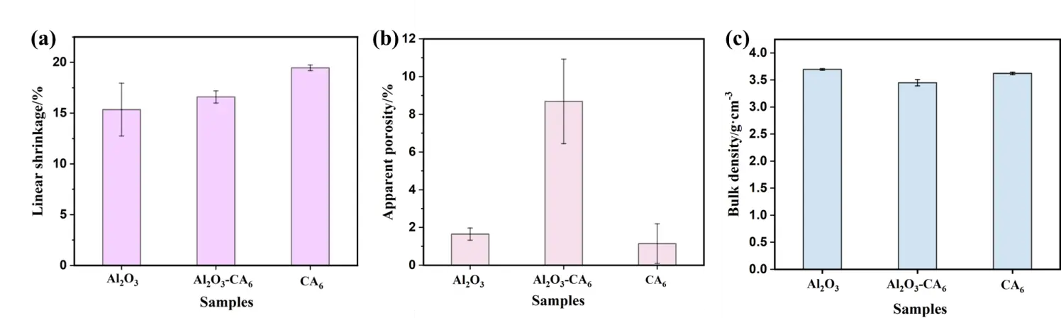
Figure 4. Sintering properties of the samples: (a) linear shrinkage, (b) apparent porosity, (c) bulk density.
3.3. Thermal Properties
Figure 5 shows the thermal conductivity and thermal diffusivity of the three sample groups measured at 100 °C, 300 °C, and 500 °C. As the temperature increases, the thermal conductivity and thermal diffusivity of all samples decrease gradually. The single-phase Al2O3 sample exhibits the most significant reduction in these properties. In contrast, the Al2O3-CA6 and CA6 samples show a more gradual decrease with increasing temperature, with nearly identical values between them. Among the three sample types, thermal conductivity decreases in the order: Al2O3 > CA6 > Al2O3-CA6. The results indicate that the thermal conductivity of the single-phase CA6 material prepared in this study is intermediate between that of single-phase Al2O3 and the Al2O3-CA6 composite. A lower thermal conductivity in the crucible material can reduce the cooling rate of the molten alloy and help maintain its superheat. Thermal conductivity is influenced by both the chemical composition and the microstructure of the material. On one hand, the larger relative atomic mass of cations in CA6 compared to Al2O3 contributes to its lower thermal conductivity. On the other hand, phonon scattering at phase boundaries further reduces the thermal conductivity of the Al2O3-CA6 composite below that of single-phase CA6, though the value remains closer to that of the continuous CA6 phase.
The heat capacity of a material reflects the change in energy of molecular thermal motion with temperature. When absorbing the same amount of heat, a refractory material with higher heat capacity experiences a smaller temperature increase compared to one with lower heat capacity, thereby improving thermal shock resistance. Table 3 presents the specific heat capacities of the three sample groups after heat treatment at 1750 °C, as measured by a laser thermal conductivity meter at various temperatures. It can be observed that above 300 °C, the heat capacity of single-phase CA6 exceeds that of single-phase Al2O3.
Table 3. Specific heat capacity of samples (J·g−1·K−1).
|
T/℃ |
Samples |
||
|---|---|---|---|
|
Al2O3 |
Al2O3-CA6 |
CA6 |
|
|
100 |
0.934 |
0.916 |
0.929 |
|
300 |
1.024 |
1.007 |
1.027 |
|
500 |
1.072 |
1.058 |
1.084 |
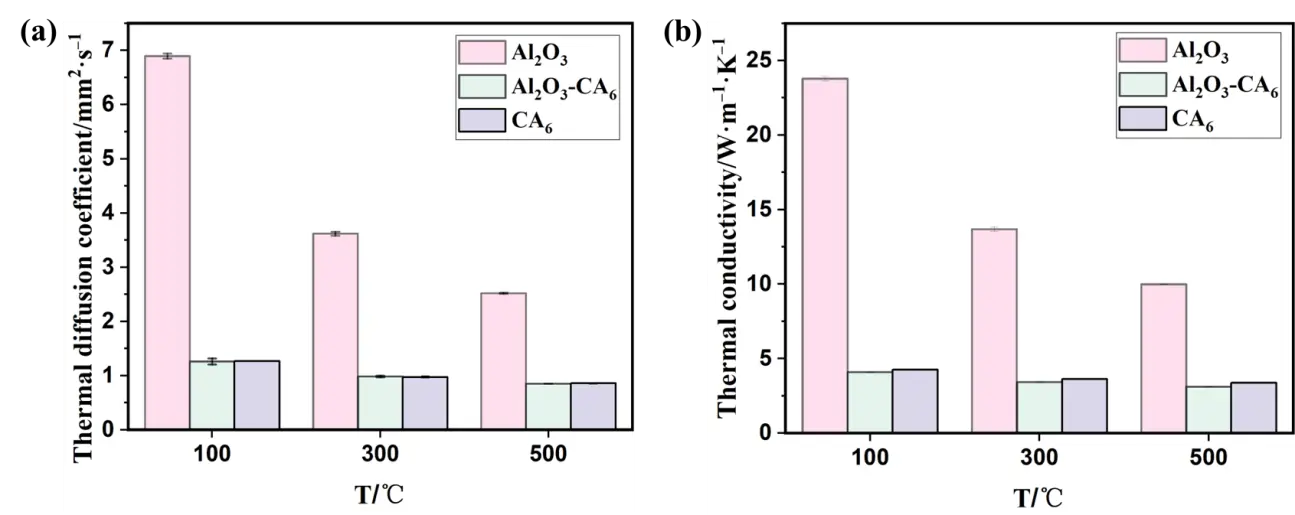
Figure 5. Thermal properties of three groups of samples: (a) thermal diffusion coefficient; (b) thermal conductivity.
As shown in Figure 6, within the temperature range of 200~1400 °C, the linear expansion rates of the three sample groups with different phase compositions increase with rising temperature, though the differences among them are relatively small. The average coefficient of thermal expansion exhibits a non-monotonic upward trend over the measured range. Between 200 °C and 1200 °C, both the single-phase Al2O3 and Al2O3-CA6 samples show a fluctuating increase in thermal expansion. In the lower temperature range (200~600 °C), the average thermal expansion coefficient of the Al2O3-CA6 samples lies between those of the other two groups. However, from 600 °C to 1400 °C, the average thermal expansion coefficient of the Al2O3-CA6 sample becomes lower than that of both single-phase materials. This behavior can be attributed to the compatible thermal expansion of Al2O3 and CA6 at lower temperatures (200~600 °C). As temperature increases, the difference in thermal expansion coefficients between Al2O3 and CA6 becomes more pronounced, inducing microcracks due to thermal stress in the composite material. The presence of these microcracks mitigates the overall thermal stress, thereby slightly reducing the apparent thermal expansion coefficient of the Al2O3-CA6 sample. Additionally, the average thermal expansion coefficient of the single-phase CA6 sample shows slight decreases in the temperature intervals of 600~800 °C and 1200~1400 °C.
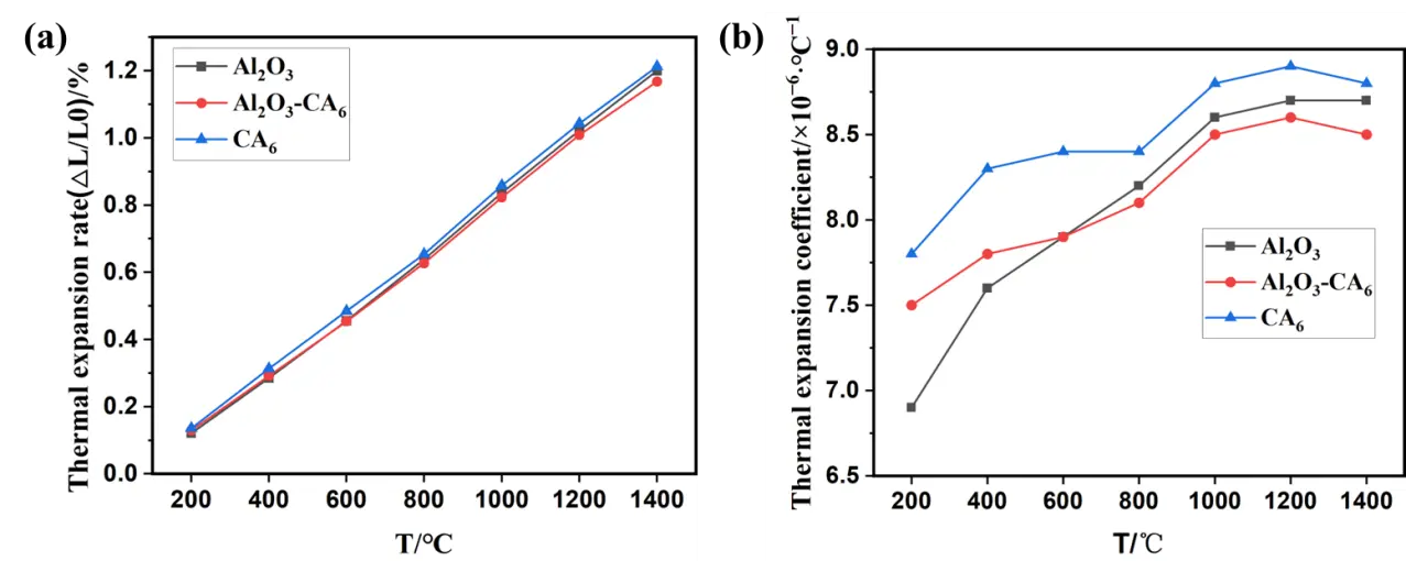
Figure 6. Thermal properties of three groups of samples: (a) linear expansion rate; (b) average linear expansion coefficient.
3.4. Mechanical Properties and Thermal Shock Resistance
Figure 7 presents the flexural strength at room temperature after heat treatment and the residual flexural strength after three thermal shock cycles for the three sample groups with different phase compositions. The single-phase CA6 exhibits the highest cold modulus of rupture, while the single-phase Al2O3 sample demonstrates the highest residual modulus of rupture after thermal shock. In contrast, the Al2O3-CA6 sample shows the lowest values for both room-temperature flexural strength and residual flexural strength after thermal cycling, indicating that the coexistence of Al2O3 and CA6 phases reduces mechanical strength under both ambient and thermal shock conditions. The residual flexural strength is significantly influenced by the thermal conductivity of the material, which is proportional to its thermal stress fracture resistance (R). Specifically, as thermal conductivity increases (in the order: Al2O3-CA6 < CA6 < Al2O3), the rate of heat transfer within the material increases, leading to a reduced temperature gradient, lower thermal stress, and consequently an increased thermal stress fracture factor. This results in a corresponding improvement in residual flexural strength, which follows the same trend: Al2O3-CA6 < CA6 < Al2O3.
The influence of porosity on the strength of ceramic materials can be expressed by the formula σf = σ0e−nP, where σf denotes the fracture strength of the material, σ0 represents the strength when porosity P equals zero, and n is a constant. This expression indicates that flexural strength decreases exponentially with increasing porosity. Accordingly, the CA6 material, which exhibits the lowest porosity among the samples studied, demonstrates the highest fracture strength. In terms of thermal conductivity, Al2O3 exhibits the highest value, followed by CA6, with Al2O3-CA6 showing the lowest. Thermal conductivity critically influences the temperature uniformity within a material under thermal transients. Higher thermal conductivity facilitates faster heat transfer, resulting in a smaller temperature gradient (ΔT) and lower thermal stress (Δσ = αEΔT/(1 − ν)), where α is the coefficient of thermal expansion, E is the elastic modulus, and ν is Poisson’s ratio. This mechanism provides the fundamental basis for thermal shock resistance. Consequently, CA6 exhibits moderate thermal shock resistance.

3.5. Alloy Corrosion Resistance of the Crucible
Figure 8 shows the microstructure of the reaction interface between the three groups of crucible samples and the Ti6Al4V alloy after melting. The upper region corresponds to the alloy, while the lower region represents the crucible refractory. As shown in Figure 8a, after melting in an Al2O3 crucible, noticeable cracks are present in the refractory material beneath the interface. These cracks pose a risk of spalling into the alloy. A magnified view of the interface (Figure 8d) reveals an erosion layer approximately 106 μm thick at the contact zone between the crucible and the alloy. This layer exhibits a relatively loose structure, accompanied by crack formation and potential spalling. However, according to the scanning results in Figure 9a, beneath this eroded region, the Ti6Al4V alloy shows minimal penetration into the dense Al2O3 refractory.
Figure 8b illustrates the interface after melting using the CA6-Al2O3 crucible. A clear boundary is visible between the crucible and the alloy. While the crucible surface appears smooth with almost no erosion, the refractory material is less dense, allowing significant alloy penetration exceeding 411 μm, as shown in Figure 8e. In contrast, Figure 8c demonstrates that melting with the CA6 crucible results in a distinct interface with superior surface smoothness compared to that of the dual-phase sample. The CA6 refractory remains relatively dense, experiencing negligible erosion and only minor penetration—approximately 100 μm—as depicted in Figure 8f.
A comparison of the interfacial microstructures in Figure 8 indicates that the thickness of the reaction layer follows the order: Al2O3-CA6 > Al2O3 > CA6. Among these, the CA6 sample exhibits the highest density, best surface finish, and the most favorable interface condition with the alloy. A dense ceramic crucible with a smooth surface effectively mitigates infiltration by the titanium-aluminum melt and reduces the erosion or dissolution of fine particles into the alloy, thereby helping maintain the purity of the ingot.
Figure 9 presents magnified views of the interface and adjacent alloy region for the three types of crucible refractories after interaction with the molten Ti6Al4V alloy. Comparative analysis of the interfacial microstructures (Figure 9a–c) indicates that the alloy melted in the single-phase CA6 crucible exhibits the least influence from the refractory material and the lowest degree of contamination. In contrast, the single-phase Al2O3 crucible shows signs of erosion at the interface (Table 4, point 1), with a risk of refractory particles spalling into the alloy. In the Al2O3-CA6 crucible, Al2O3 phases are likely incorporated into the alloy melt under intense electromagnetic stirring.
The single-phase CA6 crucible refractory demonstrates high density and excellent chemical stability, effectively limiting dissolution and minimizing contamination of the alloy melt. EDS analysis (point 2) suggests that the presence of Al2O3 in this region may result from inhomogeneous mixing during preparation. These results indicate that CA6 refractories, characterized by high density, surface smoothness, and chemical inertness, exhibit significant potential for application in titanium-aluminum alloy smelting.
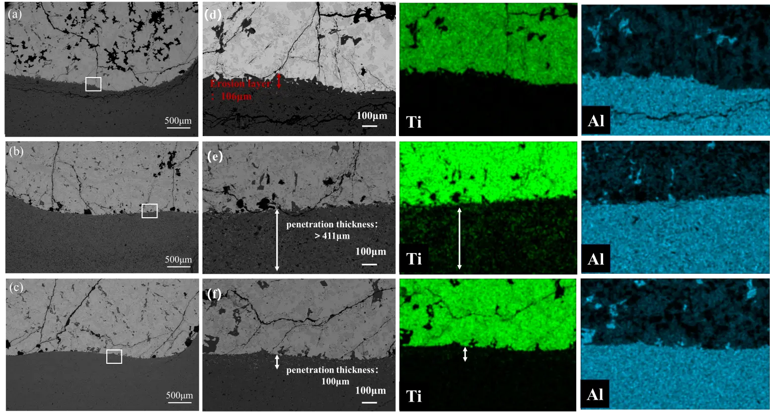
Figure 8. Microstructure and Ti element distribution at the interface reaction between crucible and alloy: (a,d) Al2O3; (b,e) Al2O3-CA6; (c,f) CA6.
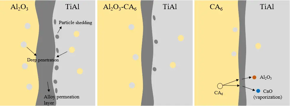
Observation of the alloy region above the interface (as shown in Figure 9d–f) further confirms that the most severe contamination occurs with the Al2O3 crucible (point 5), followed by the Al2O3-CA6 crucible (point 6). The alloy melted using the single-phase CA6 crucible shows the lowest level of contamination. Figure 10 illustrates the schematic representation of the interface reaction between titanium aluminium alloy and refractory materials, in conjunction with the interface reaction analysis diagram depicted in Figure 9 above. The Al2O3 crucible exhibited intense interfacial reduction reactions accompanied by severe particle spalling, with deep penetration occurring between the crucible and the alloy. Erosion effects were diminished in the Al2O3-CA6 crucible, where only minor penetration and erosion were observed. However, under high-temperature conditions, CA6 underwent slight decomposition, releasing Al2O3 phase into the alloy. This variation can be attributed to the strong electromagnetic stirring in the vacuum induction melting furnace, which promotes melt convection, continuously erodes the crucible wall, and enhances dissolution of refractory elements into the alloy. These findings are consistent with the erosion penetration results shown in Figure 8, confirming that the dense CA6 crucible refractory provides the best performance, with minimal alloy contamination and only slight penetration. CA6 possesses a hexagonal crystal structure, which provides higher density and better structural integrity than the corundum structure of α-Al2O3. With respect to solubility and diffusion, the compact framework of CA6 significantly hinders atomic mobility. In contrast, Al2O3 has a relatively open lattice that allows easier diffusion of Ti and Al atoms into its structure. This incorporation causes lattice distortion and bond rupture, which accelerates reduction reactions at the interface. In comparison, the low diffusion coefficient of CA6 effectively suppresses atomic exchange across the interface, thereby preventing sustained reaction progress. In addition, the low wettability of CA6 reduces the effective contact area between the crucible material and the titanium alloy melt, and any reaction products that form can act as a passivation layer, further inhibiting reaction advancement. As a result, CA6 showed the lowest reactivity in the present experiments.
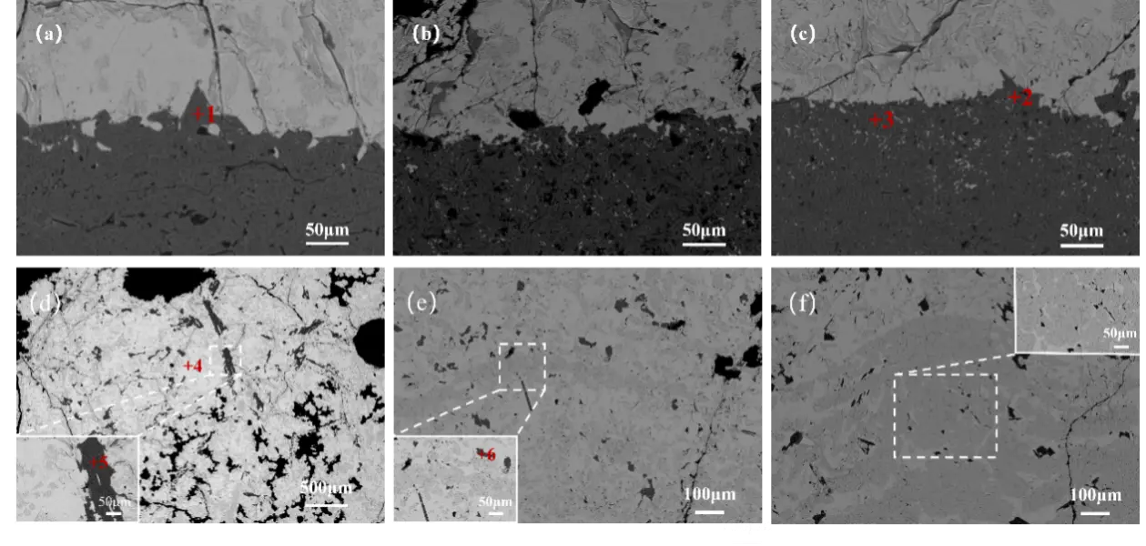
Figure 9. The interface between the crucible and the alloy and the alloy part: (a,d) Al2O3; (b,e) Al2O3-CA6; (c,f) CA6.
4. Conclusions
A dense CA6 ceramic refractory, with a bulk density of 3.62 g·cm−3, was prepared by a two-step sintering method using industrial Al2O3 and CaCO3 as raw materials. Compared to Al2O3 and CA6-Al2O3 materials, the fabricated CA6 refractory showed the highest flexural strength and medium thermal shock resistance. Moreover, the pure CA6 crucible showed best resistance to Ti6Al4V alloy corrosion. The refractory surface remained smooth and structurally dense, showing almost no erosion and only minimal penetration, with a penetration depth of approximately 100 μm. Furthermore, the alloy melted in this crucible exhibited the lowest level of contamination. These results demonstrate that dense CA6 material holds significant potential for application in the smelting of titanium-aluminum alloys.
Acknowledgements
The authors are thankful for the financially support from the National Natural Science Foundation of China (Grant Nos. 52472032 and 52172023), the Key Program of Natural Science Foundation of Hubei Province (Grant No. 2024AFA083) and the Research Project of Hubei Provincial Department of Science and Technology (Grant No. 2024CSA075).
Author Contributions
Conceptualization, L.F. and H.G.; Methodology, L.F.; Software, S.H.; Validation, S.H. and N.L.; Formal Analysis, S.H.; Investigation, S.H.; Resources, J.Z.; Data Curation, S.H.; Writing—Original Draft Preparation, S.H.; Writing—Review & Editing, L.F., C.P., N.L., H.G., J.Z. and A.H.; Visualization, S.H.; Supervision, L.F.; Project Administration, L.F.; Funding Acquisition, L.F.
Ethics Statement
Not applicable.
Informed Consent Statement
Not applicable.
Data Availability Statement
The data are available from the corresponding author on reasonable request.
Funding
This research was funded by the National Natural Science Foundation of China (Grant Nos. 52472032 and 52172023), the Key Program of Natural Science Foundation of Hubei Province (Grant No. 2024AFA083) and the Research Project of Hubei Provincial Department of Science and Technology (Grant No. 2024CSA075).
Declaration of Competing Interest
The authors declare that they have no known competing financial interests or personal relationships that could have appeared to influence the work reported in this paper.
References
-
Rack H, Qazi J. Titanium alloys for biomedical applications. Mater. Sci. Eng. C 2006, 26, 1269–1277. doi:10.1016/j.msec.2005.08.032. [Google Scholar]
-
Leyens C, Peters M. Titanium and Titanium Alloys: Fundamentals and Applications; Wiley‐VCH: Weinheim, Germany, 2006. doi:10.1002/3527602119. [Google Scholar]
-
Luo S, Wang Q, Zhang P, Li J, Liu Q. Effect of friction conditions on phase transformation characteristics in hot forging process of Ti-6Al-4V turbine blade. J. Mater. Res. Technol. 2020, 9, 2107–2115. doi:10.1016/j.jmrt.2019.12.041. [Google Scholar]
-
Pan W, Huang D, Wang W, Dou G, Lyu P. Recent Advances in High-Temperature Properties of High-Entropy Alloys. High-Temp. Mater. 2025, 2, 10011. doi:10.70322/htm.2025.10011. [Google Scholar]
-
Duan B, Yang Y, He S, Feng Q, Mao L, Zhang X, et al. History and development of γ-TiAl alloys and the effect of alloying elements on their phase transformations. J. Alloys Compd. 2022, 909, 164811. doi:10.1016/j.jallcom.2022.164811. [Google Scholar]
-
Liu C, Wang Y, Han W, Ma T, Ma D, Zhang Y. Achieving superior high-temperature strength and oxidation resistance of TiAl nanocomposite through in situ semicoherent MAX phase precipitation. ACS Appl. Mater. Interfaces 2022, 14, 8394–8403. doi:10.1021/acsami.1c21719. [Google Scholar]
-
Kagerer S, Hudak OE, Wojcik T, Hahn R, Davydok A, Schloffer M, et al. Oxidation protection of TNM alloys with Al-rich γ-TiAl-based coatings. J. Alloys Compd. 2023, 969, 172343. doi:10.1016/j.jallcom.2023.172343. [Google Scholar]
-
Fang ZZ, Paramore JD, Sun P, Chandran KR, Zhang Y, Xia Y, et al. Powder metallurgy of titanium—Past, present, and future. Int. Mater. Rev. 2018, 63, 407–459. doi:10.1080/09506608.2017.1366003. [Google Scholar]
-
Feng Q, Deng S, Liao H, Liu C, Gao P, Wang E, et al. Erosion Resistance of BaZrO3-Y2O3 Two-Phase Crucibles against Highly Active Ti2Ni Alloys. High-Temp. Mater. 2024, 1, 10003. doi:10.35534/htm.2024.10003. [Google Scholar]
-
Wang J, Kong L, Li T, Xiong T. A novel TiAl3/Al2O3 composite coating on γ-TiAl alloy and evaluating the oxidation performance. Appl. Surf. Sci. 2016, 361, 90–94. doi:10.1016/j.apsusc.2015.11.155. [Google Scholar]
-
Fashu S, Lototskyy M, Davids MW, Pickering L, Linkov V, Tai S, et al. A review on crucibles for induction melting of titanium alloys. Mater. Des. 2020, 186, 108295. doi:10.1016/j.matdes.2019.108295. [Google Scholar]
-
Wei J, Han B, Wang X, Chen J, Wei Y, Yan W, et al. Improvement in hydration resistance of CaO granules based on CaO–TiO2, CaO–ZrO2 and CaO–V2O5 systems. Mater. Chem. Phys. 2020, 254, 123413. doi:10.1016/j.matchemphys.2020.123413. [Google Scholar]
-
Tetsui T, Kobayashi T, Kishimoto A, Harada H. Structural optimization of an yttria crucible for melting TiAl alloy. Intermetallics 2012, 20, 16–23. doi:10.1016/j.intermet.2011.08.026. [Google Scholar]
-
Chen YF, Xiao SL, Tian J, Xu LJ, Chen YY. Effect of particle size distribution on properties of zirconia ceramic mould for TiAl investment casting. Trans. Nonferrous Met. Soc. China 2011, 21, s342–s347. doi:10.1016/S1003-6326(11)61603-8. [Google Scholar]
-
Eatesami D, Hadavi MM, Habibollahzade A. Melting of γ-TiAl in the alumina crucible. Russ. J. Non-Ferr. Met. 2009, 50, 363–367. doi:10.3103/S1067821209040105. [Google Scholar]
-
Li Z, Fu L, Gu H, Or SW, Huang A, Lv R. Fabrication of in-situ Ti(C,N) phase toughened Al2O3 based ceramics from natural bauxite. Ceram. Int. 2021, 47, 25497–25504. doi:10.1016/j.ceramint.2021.05.273. [Google Scholar]
-
Zhang H, Tang X, Zhou C, Zhang H, Zhang S. Comparison of directional solidification of γ-TiAl alloys in conventional Al2O3 and novel Y2O3-coated Al2O3 crucibles. J. Eur. Ceram. Soc. 2013, 33, 925–934. doi:10.1016/j.jeurceramsoc.2012.11.006. [Google Scholar]
-
Zhu J, Kamiya A, Yamada T, Shi W, Naganuma K, Mukai K. Surface tension, wettability and reactivity of molten titanium in Ti/yttria-stabilized zirconia system. Mater. Sci. Eng. A 2002, 327, 117–127. doi:10.1016/S0921-5093(01)01732-4. [Google Scholar]
-
Fu BG, Wang HW, Zou CM, Ma P, Wei ZJ. Interfacial reactions between Ti-1100 alloy and CaO crucible during casting process. Trans. Nonferrous Met. Soc. China 2014, 24, 3118–3125. doi:10.1016/S1003-6326(14)63450-6. [Google Scholar]
-
Tetsui T, Kobayashi T, Mori T, Kishimoto T, Harada H. Evaluation of Yttria Applicability as a Crucible for Induction Melting of TiAl Alloy. Mater. Trans. 2010, 51, 1656–1662. doi:10.2320/matertrans.MAW201002. [Google Scholar]
-
Salomão R, Ferreira VL, de Oliveira IR, Souza ADV, Correr WR. Mechanism of pore generation in calcium hexaluminate (CA6) ceramics formed in situ from calcined alumina and calcium carbonate aggregates. J. Eur. Ceram. Soc. 2016, 36, 4225–4235. doi:10.1016/j.jeurceramsoc.2016.05.026. [Google Scholar]
-
Cui S, Wang Q, Zhou Y, Mao D, Bao J, Song X. Effect of nickel oxide and titanium oxide on the microstructural, optical, and mechanical properties of calcium hexaaluminate ceramics. Ceram. Int. 2021, 47, 35302–35311. doi:10.1016/j.ceramint.2021.09.073. [Google Scholar]
-
Salomão R, Ferreira VL, Costa LMM, de Oliveira IR. Effects of the initial CaO-Al2O3 ratio on the microstructure development and mechanical properties of porous calcium hexaluminate. Ceram. Int. 2018, 44, 2626–2631. doi:10.1016/j.ceramint.2017.11.010. [Google Scholar]
-
Liu J, Gu H, Zhang M, Huang A, Li H. Improvement in fatigue resistance performance of corundum castables with addition of different size calcium hexaluminate particles. Ceram. Int. 2019, 45, 225–232. doi:10.1016/j.ceramint.2018.09.155. [Google Scholar]
-
Qi X, Fu L, Du R, Gu H, Chen D, Yang S, et al. Properties of various CaO-Al2O3-TiO2 refractories and their reaction behaviours in contact with Ti6Al4V melts. J. Alloy Compd. 2023, 959, 170599. doi:10.1016/j.jallcom.2023.170599. [Google Scholar]