Long-Term Creep Performance of Ferritic SOC Interconnect Steel

Long-Term Creep Performance of Ferritic SOC Interconnect Steel
Bernd Kuhn
1,*,†
 Torsten Fischer
2,†
Torsten Fischer
2,†
Received: 06 October 2025 Revised: 27 October 2025 Accepted: 26 November 2025 Published: 05 December 2025

© 2025 The authors. This is an open access article under the Creative Commons Attribution 4.0 International License (https://creativecommons.org/licenses/by/4.0/).
1. Introduction
Ferritic stainless steels are frequently utilized as construction materials for metallic housings and interconnects of high temperature solid oxide fuel/electrolysis cells (SOCs), because of their high resistance against oxidation attack and favorably low coefficient of thermal expansion (CTE) [1,2,3], which matches that of the electroactive ceramic components (electrolyte, cathode and anode) [3,4,5]. Excessive work has been done considering commodity materials as well as specialty steels, exclusively designed for SOC application [2,3,5,6,7]. Crofer®22 H [8,9,10,11] is a well-known representative of the latter, which offers improved creep strength above the aforementioned steels. Its strength is reached by a combination of solid-solution strengthening by W and precipitation strengthening by secondary Laves phase precipitates. The effectiveness of precipitation strengthening depends on the particle microstructure set before the start of operation, as well as the applied operating temperature and time. While the initial precipitate microstructure, given the chemical composition of the steel, depends on the manufacturing history of the component, the latter is governed by the thermodynamic stability of the formed Laves phase particles during operation. For SOC designs featuring interconnects with a thickness of less than a millimeter [12], creep resistance, and possible changes by production induced or application driven microstructural alterations may be significant for long-term operation.
This present paper gives an assessment of the long-term creep properties of the Laves phase strengthened ferritic steel Crofer®22 H in two differing initial microstructural conditions: The commercially available solution treated, i.e., low dislocation density, state and a deformed, i.e., high dislocation density, condition.
2. Experimental
2.1. Materials and Preparation
Commercially available Crofer® 22 H (VDM metals GmbH), along with a lab trial melt of matching chemical composition were creep tested for this study. From both grades, creep specimens were machined from plate material (Crofer® 22 H: 12 mm thickness, trial steel: 22 mm thickness). The trial steel was manufactured by vacuum induction melting with subsequent hot-rolling and water quenching, Crofer®22 H was produced by arc melting, hot-rolling and solution annealing (1075 °C, continuous furnace, water jet cooling). For this reason, Crofer®22 H prevailed in a homogeneous equi-axed microstructure, the model alloy in a deformed microstructural state with grains elongated along the rolling direction (Figure 1). The chemical compositions of the tested alloys are given in Table 1.
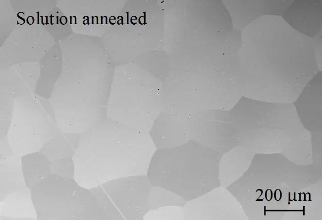
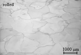
Table 1. Chemical compositions of the commercial and the trial alloy.
|
Material |
Thickness [mm] |
Fe |
Cr |
W |
Nb |
Mn |
Si |
Ti |
Al |
La |
C |
N |
|---|---|---|---|---|---|---|---|---|---|---|---|---|
|
[wt.-%] |
||||||||||||
|
Crofer® 22 H |
12 |
Balance |
22.93 |
1.94 |
0.51 |
0.43 |
0.21 |
0.07 |
0.02 |
0.08 |
0.007 |
0.015 |
|
Trial |
2.5 |
Balance |
22.32 |
2.02 |
0.48 |
0.43 |
0.24 |
0.06 |
0.09 |
0.09 |
<0.002 |
0.007 |
2.2. Mechanical Testing
Cylindrical specimens with a gauge diameter/length of 6.4/32 mm were prepared from the plate materials. An Instron Type 1382 testing machine was applied for tensile experiments with strain rates of 10−3 s−1 and 10−5 s−1. Creep testing at constant load was carried out either in single-specimen, lever arm creep machines with continuous deformation measurement at the gauge length of the specimen or (stresses < 10 MPa) in multi-specimen testers without continuous measurement of specimen strain. In this case, discontinuous strain measurement was carried out after cooling to ambient temperature, unloading and taking the specimens from the multi-specimen tester for gauge length measurement. The procedure was repeated every 500 h for the initial 5000 h of the creep experiments and every 1000 h afterwards.
Electrical three-zone furnaces, controlled to an accuracy of ±2 °C, were utilized in the case of the single-specimen creep and tensile testing machines, while electrical five-zone furnaces (accuracy of ±3 °C) were applied in the case of the multi-specimen testers. To ensure temperature stability, all specimens were held at the testing temperature for one hour before initiating the experiment.
2.3. Microstructural Investigation
Spark eroded specimens from the plate materials were used for the investigation of the initial microstructures. For metallographic characterization the specimens were mounted in epoxy resin, ground, polished and characterized by light (OM—Leica MEF4, Leica Microsystems, Wetzlar, Germany) and scanning electron microscopy with energy/wavelength dispersive X-ray spectroscopy (SEM/EDX—Zeiss Supra 50 VP, Carl Zeiss Microscopy Deutschland GmbH, Oberkochen, Germany/Oxford Instruments Inca/Wave, Oxford Instruments plc, High Wycombe, UK).
3. Results and Discussion
3.1. Microstructural Properties
Solution treated Crofer® 22 H demonstrates an initial, single-phase microstructure with equi-axed grains in the size range from 150 to 250 μm (Figure 1a). The hot-rolled trial steel exhibits a larger grain size and grains elongated along the rolling direction (Figure 1b).
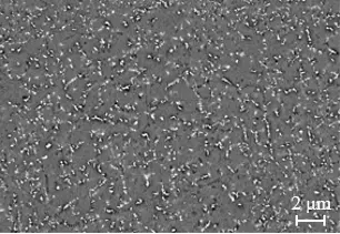
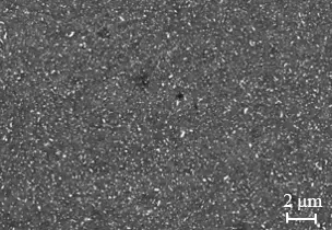
The impact of thermomechanical [14,15,16,17,18] and heat treatment [19] states on the precipitation of Laves phase particles and its significance on the mechanical response of the investigated steel grades is well documented. To exemplify the effect of increased dislocation density (in this case from hot-rolling), micrographs of the rolled trial and the solution treated commercial steel after annealing at 700 °C for 10 h are compared in Figure 2.
 |
 |
|
(a) |
(b) |
Figure 2. Laves phase precipitation in (a) commercial Crofer® 22 H and (b) the trial steel after annealing at 700 °C for 10 h.
Annealing for 10 h at 700 °C results in the formation of a multitude of small Laves phase precipitates in both materials. In direct comparison, the two-fold impact of deformation in the rolled trial steel becomes obvious: Because of increased density of dislocations, which act as preferred nucleation sites, the trial steel forms more and notably smaller particles (Figure 2b), which are more effective in hindering dislocation motion. Solution annealing results in larger precipitates and increased interparticle spacing. Particles as small as those in the rolled condition are almost absent (Figure 2a).
3.2. Mechanical Properties
The early-stage microstructural differences outlined in the previous section do have a significant effect on the creep response, especially in the primary stage of creep. This even affects the following (limited) secondary stage and the transition into the creep life dominating tertiary creep stage [20,21,22].
To evaluate the importance of thermomechanical treatment history before mechanical loading at high temperature, both steels were studied in high (10−3·s−1) and low strain-rate (10−5·s−1) tensile and mid- (<5000 h) to long-term (>5000 h) creep experiments as outlined in Section 2.2. Table 2, Table 3 and Table 4 summarize the mechanical tests carried out and the results obtained in the framework of this study.
Table 2. Mechanical testing schedule.
|
Material |
Product Form |
Thickness [mm] |
Test Type |
Temperature [°C] |
|
|---|---|---|---|---|---|
|
Trial |
Plate |
22 mm |
hot tensile |
creep |
700/800 °C |
|
Crofer® 22 H |
Plate |
12 mm |
hot tensile |
creep |
700/800 °C |
Table 3. Ultimate tensile strength values obtained in hot-tensile testing applying different strain rates.
|
Alloy |
Temperature [°C] |
Strain Rate |
UTS [MPa] |
|---|---|---|---|
|
[s−1] |
|||
|
Trial |
700 |
10−3 |
139 |
|
Crofer® 22 H |
150 |
||
|
Trial |
700 |
10−5 |
97 |
|
Crofer® 22 H |
103 |
||
|
Trial |
800 |
10−3 |
66 |
|
Crofer® 22 H |
68 |
||
|
Trial |
800 |
10−5 |
42 |
|
Crofer® 22 H |
35 |
Table 4. Steady-state/minimum deformation rates obtained in creep testing.
|
Alloy |
Temperature [°C] |
Stress [MPa] |
SS [%−1] |
Time [h] |
Status |
|---|---|---|---|---|---|
|
Crofer® 22 H |
700 |
7 |
6.2 × 10⁻⁷ |
48,523 |
in progress |
|
Trial |
10 |
4.0 × 10⁻⁷ |
76,040 |
in progress |
|
|
Crofer® 22 H |
9.2 × 10⁻⁷ |
48,489 |
in progress |
||
|
Trial |
15 |
1.2 × 10⁻⁶ |
76,034 |
in progress |
|
|
Crofer® 22 H |
17 |
6.1 × 10⁻⁶ |
13,729 |
in progress |
|
|
Crofer® 22 H |
20 |
1.2 × 10⁻⁵ |
14,729 |
ruptured |
|
|
Trial |
800 |
7 |
1.1 × 10⁻⁶ |
62,006 |
in progress |
|
Crofer® 22 H |
6.8 × 10⁻⁶ |
16,922 |
in progress |
||
|
Trial |
10 |
5.2 × 10⁻⁶ |
14,849 |
ruptured |
|
|
Crofer® 22 H |
3.2 × 10⁻⁵ |
5809 |
ruptured |
||
|
Crofer® 22 H |
17 |
4.3 × 10⁻⁴ |
1429 |
ruptured |
|
|
Crofer® 22 H |
20 |
8.2 × 10⁻⁴ |
632 |
ruptured |
While the short-term tensile strength is merely unaffected by the thermomechanical treatment state (cf. Table 3), the long-term creep properties appear to be improved in the deformed trial steel. Increased initial dislocation density yields a drop in minimum creep rates obtained at any stress level and both temperatures.
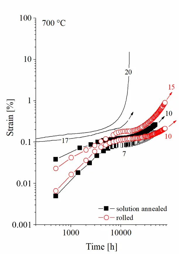
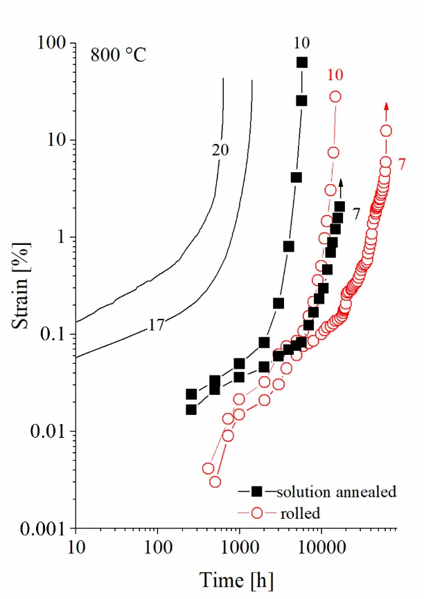
From the creep curves of the two steels recorded at 700 °C and 800 °C (Figure 3), it becomes obvious that the rolled variant yields lower primary and secondary creep strain and a shifted transition into the tertiary creep stage, which results in prolonged creep life at both temperatures. At 700 °C and an applied stress of 10 MPa, the annealed/rolled variant reached transition to the tertiary creep regime after approximately 8000 h/15,000 h. The strain levels reached so far in the experiments in progress (experimental durations reached by now are in the range of 76,000 h) already indicate improved creep life potential. At 800 °C and 7/10 MPa, the annealed commercial steel clearly left the secondary stage of creep at approximately. 2000 h/1000 h, while in the case of the rolled trial version, the transition was reached after 8000 h/5000 h. The ruptured 10 MPa trial steel specimen reached a creep life of 14,849 h, its annealed counterpart ruptured after 5809 h, which calculates to a creep life extension by a factor of 2.55 caused by thermomechanical treatment history.
 |
 |
|
(a) |
(b) |
Figure 3. Creep curves of the two steels obtained at (a) 700 °C and (b) 800 °C (experiments in progress marked by arrows).
“Norton’s power law” relates the steady-state strain rate $$\dot{\epsilon}$$SS to the applied stress at a given temperature [22,23]. Figure 4 displays the minimum strain rates determined from the creep experiments (cf. Table 4) correlated to the applied stress level applying Norton’s power law equation in log $$\dot{\epsilon}$$/logσ diagrams to evaluate the stress exponent (cf. Figure 4). The creep testing results are plotted together with the ultimate tensile strength values of hot-tensile tests with two different strain rates in so called “Norton-Plots”.
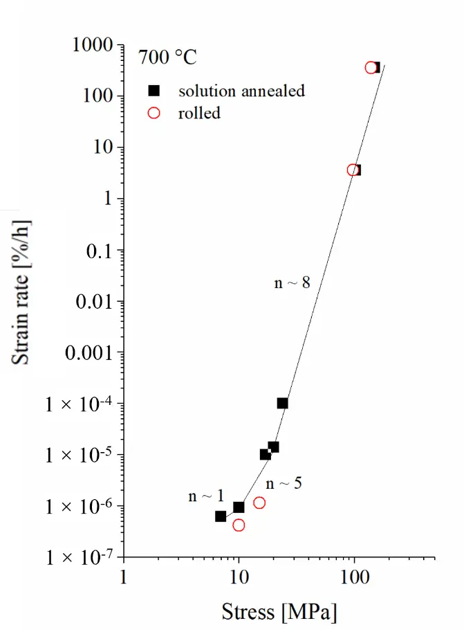
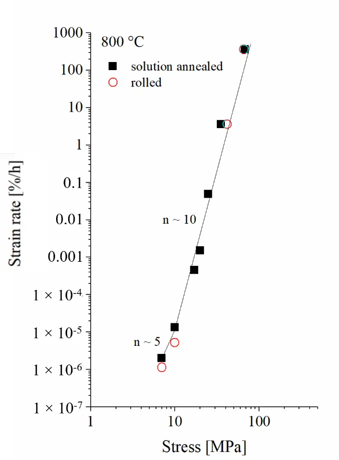
The Norton plots underline that the rolled trial steel yielded consistently lower minimum creep rates in the low-stress creep experiments. In combination with the shift of the transition from the minimum creep rate secondary to the tertiary creep range towards longer testing times and the lower level of primary creep strain this results in significantly extended service life. The lower level of primary creep strain is caused by the initially increased dislocation density due to the thermomechanical treatment (i.e., rolled) condition, which has a strong impact on the microstructural and thus mechanical response to loading at high temperature [14,15,16,17,18]. Dislocations act as preferred nucleation sites for the strengthening Laves phase particles, which results in a larger number of smaller precipitates (cf. Figure 2b). In addition, dislocations accelerate precipitate nucleation and reduce the width of particle-free zones (PFZ) along grain boundaries [16]. As a result in the rolled trial material a higher number of—moreover smaller and for this reason more effectively strengthening particles—is produced during heating to and equilibration at the designated testing temperature than in the solution-annealed commercial material (Figure 2a). In Laves phase strengthened steels the transition to the tertiary creep regime is caused by the accumulation of creep strain in PFZs located alongside grain boundaries [16]. Since the PFZs initially have a smaller width in the rolled trial material, the critical width is consequently reached later, which can explain the time shifted transition into the tertiary stage of creep deformation.
Microstructures obtained from quasi stress-free head sections of the 800 °C/7 MPa creep specimens (after 62,006/16,922 h in case of the rolled trial/solution-annealed commercial variant) are displayed in Figure 5. The grain interiors appear sporadically decorated by coarsened precipitates in both materials after long-term exposure. Intragranular precipitates smaller than 500 nm are almost absent. Grain boundaries are covered by large Laves phase particles and particle free zones (PFZs) developed alongside these. According to its increased exposure time, microstructural degradation, i.e., precipitate coarsening, appears more pronounced in the rolled trial material. A quantitative, microstructural evaluation was not possible in the context of this study. However, it can be assumed that the effectiveness of the coarsening precipitates in obstructing creep deformation decreases with increasing time. As discussed in [13], solid solution strengthening by W remains the main long-term strengthening mechanism in this type of steel at temperatures exceeding 650 °C. The increase in creep rupture life encountered in the case of the deformed trial steel is therefore likely to be largely caused by its greatly reduced levels of primary and secondary creep strain in combination with the later transition into the tertiary stage of creep.
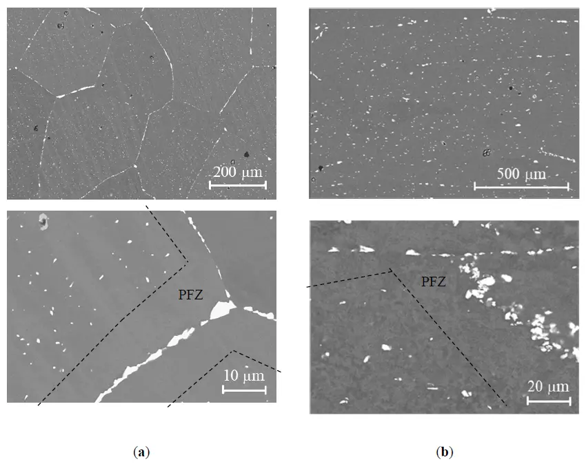
Figure 5. Microstructure of (a) the rolled trial steel after 62,006 and (b) the solution-annealed commercial variant after 16,922 h (head sections of 800 °C/7 MPa creep specimens).
In the case of the high deformation rate hot-tensile experiments, initially increased dislocation density of the rolled condition plays a subordinate role only. The forced deformation results in a sufficiently high number of dislocations in the solution-annealed material, too. Consequently, both materials show consistent results within the range of repeatability in the hot-tensile tests (Figure 4).
4. Conclusions
The investigation into the creep behavior of solution-annealed Crofer®22 H and its rolled trial steel variant reveals significant insights into microstructural changes and resulting mechanical response at high temperature. Commercial Crofer®22 H presents a single-phase microstructure characterized by equi-axed grains, while the hot-rolled variant displays larger grains that are elongated in the rolling direction. In response to short-term annealing, both materials exhibit the formation of Laves phase precipitates. However, the trial steel benefits from increased dislocation density, which leads to the generation of smaller and more numerous precipitates. In the case of the trial steel, this characteristic enhances the obstruction of dislocation movement, further distinguishing its mechanical response even in the long term. The differences in microstructure substantially affect the mechanical properties, particularly regarding creep resistance: The rolled trial steel demonstrates superior performance compared to solution-annealed Crofer®22 H. Notably, the deformed trial variant experiences reduced primary creep strain, minimum creep rate and delayed transition to the tertiary creep stage, which can well be explained by microstructural mechanisms known in Laves phase strengthened steels. These result in prolonged creep life, which signifies the advantages conferred by thermomechanical treatment, confirming its critical role in enhancing the operational capabilities of the material under creep conditions.
In summary, the processing history of the material and the resulting microstructural attributes play a significant role in determining its mechanical behavior, demonstrating how effective thermomechanical processing can elevate performance in high-temperature applications. Consequently, the thermomechanical treatment history of Crofer®22 H stack components shall be considered relevant for the design and lifetime prediction of high-temperature electrochemical conversion systems.
Acknowledgement
The authors gratefully acknowledge the continuous support of Forschungszentrum Jülich GmbH, especially the support of W. Lange, M. Braun and A. Moser in long-term creep testing, V. Gutzeit and J. Bartsch in metallographic preparation, E. Wessel in microstructural examination.
Author Contributions
Conceptualization, B.K.; Methodology, B.K.; Validation, T.F.; Formal Analysis, T.F.; Investigation, B.K. and T.F.; Resources, B.K.; Data Curation, T.F.; Writing—Original Draft Preparation, B.K.; Writing—Review & Editing, T.F.; Visualization, B.K. and T.F.; Supervision, B.K.; Project Administration, B.K.; Funding Acquisition, B.K.
Ethics Statement
Not applicable.
Informed Consent Statement
Not applicable.
Data Availability Statement
Not available.
Funding
Funding of steel development was provided by the German Ministry of Economy and Energy under grant numbers 0326879 and 0327766, which is greatly appreciated.
Declaration of Competing Interest
The authors declare that they have no known competing financial interests or personal relationships that could have appeared to influence the work reported in this paper.
References
-
Fergus JW. Metallic interconnects for solid oxide fuel cells. Mater. Sci. Eng. A 2005, 397, 271–283. doi:10.1016/j.msea.2005.02.047. [Google Scholar]
-
Quadakkers WJ, Pirón-Abellán J, Shemet V, Singheiser L. Metallic interconnectors for solid oxide fuel cells—A review. Mater. High Temp. 2003, 20, 115–127. doi:10.1179/mht.2003.015. [Google Scholar]
-
Ueda M, Taimatsu H. European Solid Oxide Fuel Cell Forum Proceedings; McEvoy AJ, Ed.; The European Fuel Cell Forum: Lucerne, Switzerland, 2000; Volume 2, pp. 837–843. [Google Scholar]
-
Uehara T, Ohno T, Toji A. Proceedings of the 5th European Solid Oxide Fuel Cell Forum, Luzern, Switzerland, 1–5 July 2002; Huijsmans J, Ed.; European Fuel Cell Group: Lucerne, Switzerland, 2002; p. 281. [Google Scholar]
-
Pirón-Abbellán J, Shemet V, Tietz F, Singheiser L, Quadakkers WJ, Gil A. Solid Oxide Fuel Cells VII—Electrochemistry Society Proceedings PV 2001-16; Yokokawa H, Singhal SC, Eds.; The Electrochemical Society: Pennington, NJ, USA, 2001; pp. 811–819. [Google Scholar]
-
Honegger K, Plas A, Diethelm R, Glatz W. In Proceedings of the SOFC-VII, Tsukuba, Japan, 3–8 June 2001; Yokokawa H, Singhal SC, Eds.; The Electrochemical Society: Pennington, NJ, USA, 2001; Volume 16, p. 803. [Google Scholar]
-
Hojda R, Heimann W, Quadakkers WJ. Großserientaugliches Werkstoffkonzept für Hochtemperatur-Brennstoffzellen. ThyssenKrupp Techforum, ThyssenKrupp AG. July 2003, 20–23. Available online: https://ucpcdn.thyssenkrupp.com/_legacy/UCPthyssenkruppAG/assets.files/media/publikationen/thyssenkrupp-techforum/2003/techforum_d_7_2003.pdf (accessed on 4 December 2025). [Google Scholar]
-
Froitzheim J, Meier GH, Niewolak L, Ennis PJ, Hattendorf H, Singheiser L, et al. Development of high strength ferritic steel for interconnect application in SOFCs. J. Power Sources 2008, 178, 163–173. doi:10.1016/j.jpowsour.2007.12.028. [Google Scholar]
-
Hattendorf H, Niewolak L, Kuhn B, Ibas O, Quadakkers WJ. Crofer® 22 H—A New High Strength Ferritic Steel for Interconnectors in SOFCs. In Proceedings of the 9th European Fuel Cell Forum, Lucerne, Switzerland, 29 June–2 July 2010; Chapter 12, pp. 12-1–12-13. [Google Scholar]
-
Crofer® 22 H—Material Data Sheet. Available online: https://www.vdm-metals.com/fileadmin/user_upload/Downloads/Data_Sheets/Data_Sheet_VDM_Crofer_22_H.pdf (accessed on 4 December 2025). [Google Scholar]
-
Quadakkers WJ, Niewolak L, Ennis PJ. Ferritic Steel Used for a Fuel Cell Stack or a Bipolar Plate for a Fuel Cell Stack Contains Precipitations of an Intermetallic Phase. PCT/DE2007/000166, WO2007093148-A1, DE102006007598-A1, 18 February 2006. [Google Scholar]
-
Lamp P, Tachtler J, Finkenwirth O, Mukerjee S, Shaffer S. Development of an auxiliary power unit with solid oxide fuel cells for automotive applications. Fuel Cells 2003, 3, 146–152. doi:10.1002/fuce.200332107. [Google Scholar]
-
Kuhn B, Jimenez CA, Niewolak L, Hüttel T, Beck T, Hattendorf H, et al. Effect of Laves phase strengthening on the mechanical properties of high Cr ferritic steels for solid oxide fuel cell interconnect application. Mater. Sci. Eng. A 2011, 528, 5888–5899. doi:10.1016/j.msea.2011.03.112. [Google Scholar]
-
Kuhn B, Talik M. Impact of Processing on the Creep Properties of High Performance Ferritic (HiperFer) Steels. Metals 2022, 12, 1459. doi:10.3390/met12091459. [Google Scholar]
-
Pöpperlová J, Wipp D, Kuhn B, Bleck W. Laves Phase Precipitation Behavior in HiperFer (High Performance Ferritic) Steel with and without Boron Alloying. Metals 2023, 13, 235. doi:10.3390/met13020235. [Google Scholar]
-
Fan X, Kuhn B, Pöpperlova J, Bleck W, Krupp U. Thermomechanically Induced Precipitation in High-Performance Ferritic (HiperFer) Stainless Steels. Appl. Sci. 2020, 10, 5713. doi:10.3390/app10165713. [Google Scholar]
-
Fan X, Kuhn B, Pöpperlova J, Bleck W, Krupp U. Impact of Tungsten on Thermomechanically Induced Precipitation of Laves Phase in High Performance Ferritic (HiperFer) Stainless Steels. Appl. Sci. 2020, 10, 4472. doi:10.3390/app10134472. [Google Scholar]
-
Kuhn B, Talik M, Niewolak L, Zurek J, Hattendorf H, Ennis PJ, et al. Development of high chromium ferritic steels strengthened by intermetallic phases. In Proceedings of the 8th Conference on Advances in Materials Technology for Fossil Power Plants, Waikoloa Village, HI, USA, 22–25 October 2013; pp. 1018–1026. [Google Scholar]
-
Kuhn B, Talik M. Heat Treatment of High-Performance Ferritic (HiperFer) Steels. Materials 2023, 16, 3500. doi:10.3390/ma16093500. [Google Scholar]
-
Kuhn B, Talik M, Niewolak L, Zurek J, Hattendorf H, Ennis PJ, et al. Development of high chromium ferritic steels strengthened by intermetallic phases. Mater. Sci. Eng. A 2014, 594, 372–380. doi:10.1016/j.msea.2013.11.048. [Google Scholar]
-
Kuhn B, Talik M, Fischer T, Fan X, Yamamoto Y, Lopez Barrilao J. Science and Technology of High Performance Ferritic (HiperFer) Stainless Steels. Metals 2020, 10, 463. doi:10.3390/met10040463. [Google Scholar]
-
Norton FH. The Creep of Steel at High Temperatures; McGraw-Hill: New York, NY, USA, 1929. [Google Scholar]
-
Mukherjee AK, Bird JE, Dorn JE. Experimental correlation for high-temperature creep. Trans. ASM 1969, 62, 155–179. [Google Scholar]