Review of Ground Insulation Resistance Detection Methods for Photovoltaic (PV) Systems

Review of Ground Insulation Resistance Detection Methods for Photovoltaic (PV) Systems
Wenping Zhang
1,*
 Linyan Xu
1
Yiming Wang
1
Po Xu
1
Yiming Wang
1
Ke Ma
2
Linyan Xu
1
Yiming Wang
1
Po Xu
1
Yiming Wang
1
Ke Ma
2
Received: 04 September 2025 Revised: 02 December 2025 Accepted: 08 December 2025 Published: 12 December 2025

© 2025 The authors. This is an open access article under the Creative Commons Attribution 4.0 International License (https://creativecommons.org/licenses/by/4.0/).
Graphical Abstract
1. Introduction
Renewable energy is becoming increasingly important in all sectors as the world moves toward a more sustainable energy future [1,2,3]. The PV industry, with its numerous benefits such as cleanliness and sustainability, has grown rapidly and emerged as a key player in the energy sector. The safe and stable operation of PV systems has a significant impact on power generation efficiency and reliability. However, the ground insulation resistance of PV modules is particularly vulnerable to environmental factors, which could pose a ground safety risk. Specifically, the performance of insulating materials gradually deteriorates due to multiple factors, such as aging, mechanical damage, electrical stress, and environmental erosion [4,5,6,7]. When the ground insulation resistance falls below a certain threshold, abnormal leakage currents may occur. This can jeopardize personal safety, cause equipment overheating [8,9], and undermine system reliability. Therefore, insulation resistance is a critical parameter that directly reflects the electrical insulation quality of PV systems and is required to ensure system reliability and energy efficiency. Consequently, developing effective detection methods is critical for ensuring the reliability of PV systems [10,11].
Numerous studies have investigated ground insulation resistance detection technologies for PV systems, proposing several detection methods [12,13,14,15,16,17,18,19]. These studies are primarily concerned with addressing the following core challenges.
-
-
How to perform ground resistance detection on the DC- or AC-side of PV inverters prior to system startup.
-
-
How to detect ground resistance when the system is in operation conditions, particularly when power switches are turned on.
-
-
How to locate faults when low ground resistance occurs.
In order to systematically summarize solutions to these challenges and provide practical references, this paper analyzes common detection methods by comparing their technical principles and performance. Furthermore, fault locating strategies at the system-, string-, branch-, and module-levels are discussed.
The structure of this article is as follows. Section 2 discusses the fundamental theory of ground insulation resistance in PV systems. Section 3 provides an in-depth review of various ground insulation resistance detection methods, evaluating their performance from technical principles to implementation mechanisms. Section 4 examines fault locating technologies at various levels and discusses the performance of different methods. Section 5 concludes the paper with a comprehensive summary and outlook on future developments.
2. Fundamental Theory of Ground Insulation Resistance
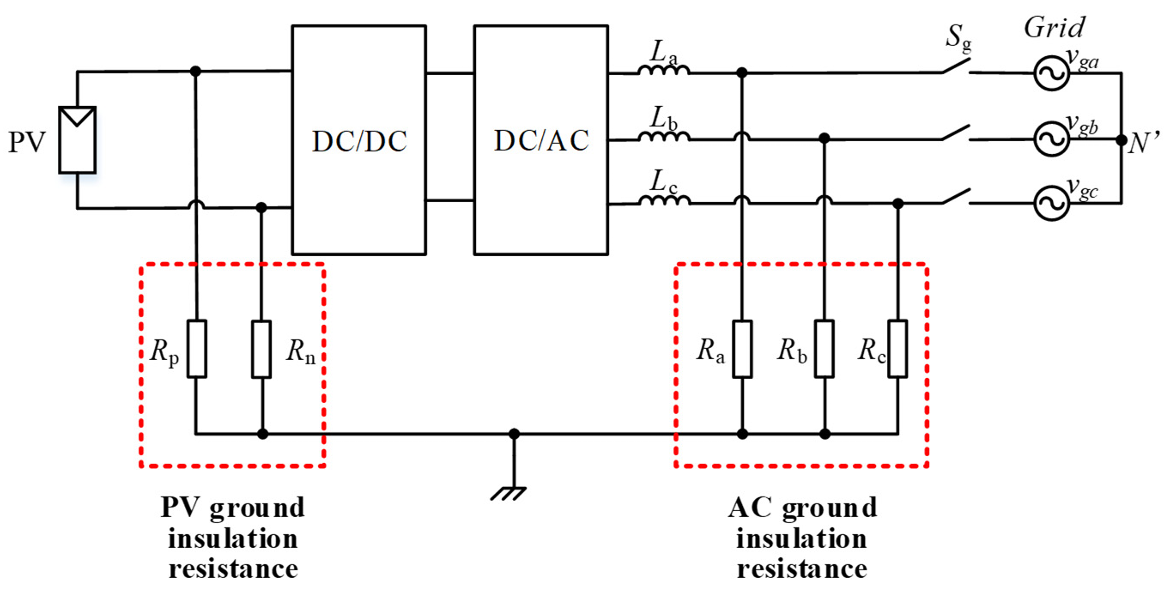
Figure 1 depicts a typical PV system [1]. In this system, ground insulation resistance is classified into two types: DC-side and AC-side. On the DC-side, the ground insulation resistance is represented by Rp and Rn, which represent the resistance from the PV positive and negative poles to ground. On the AC-side, the ground insulation resistance is represented by Ra, Rb, and Rc, which represent the resistance of each AC phase to ground.
Higher insulation resistance indicates better insulation performance, which can protect against potential safety hazards caused by leakage currents. To ensure the safety of PV systems, ground insulation resistance should always be higher than the safety threshold. Therefore, the primary goal of insulation detection is to determine whether the ground insulation resistance falls below the safety threshold [5,6,7,8,9].
Because ground insulation resistance detection methods are inextricably linked to system architecture, the following introduces several common system architectures first.
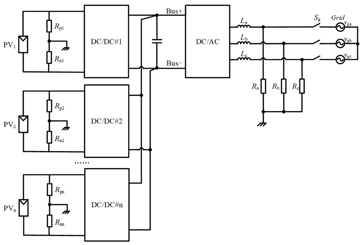
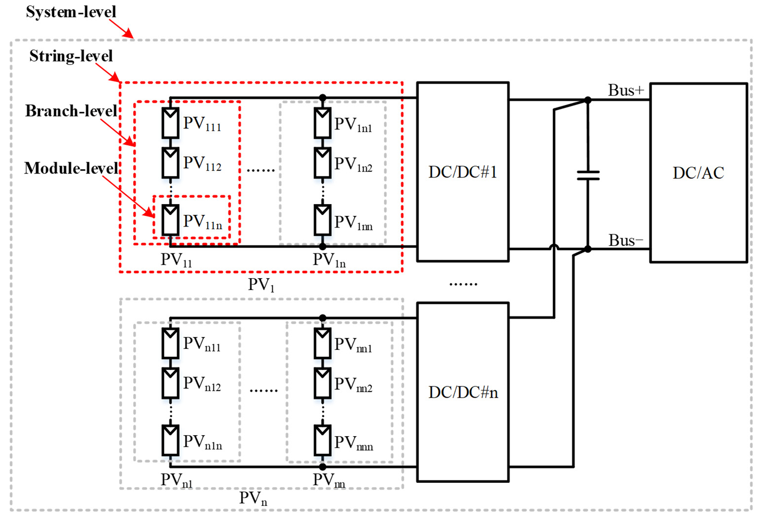
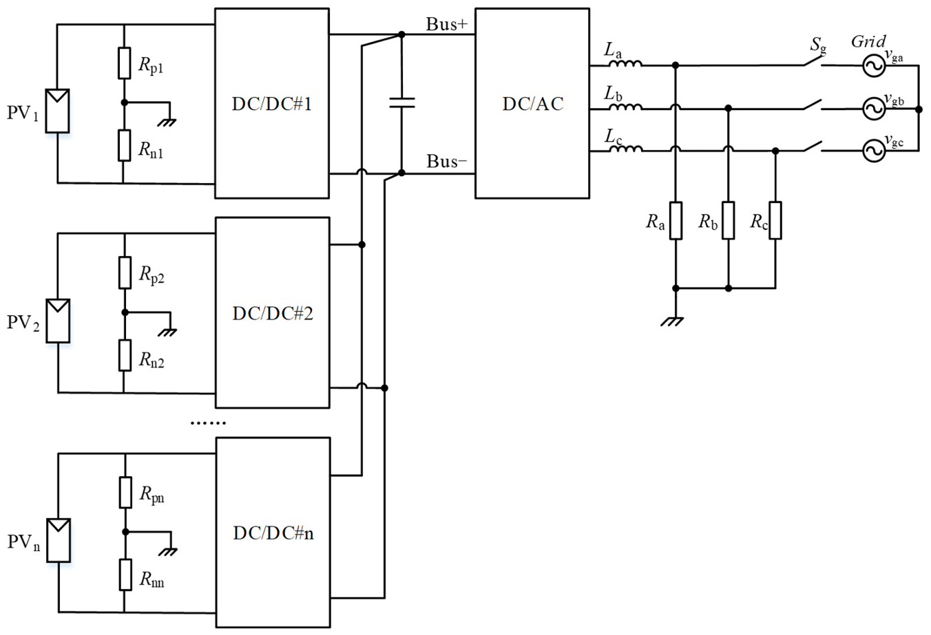
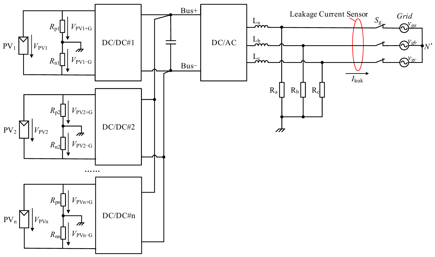
Figure 2 depicts a string-type PV system with multiple PV strings connected in parallel to the DC-bus via DC-DC converters [20,21,22,23]. The ground resistance of PV strings is typically detected in two ways: (1) independently for each string, and (2) centralized monitoring via the DC-bus. It is important to point out that the ground insulation resistance detection and fault locating methods described in this paper mainly focus on string-type PV systems. However, these methods can also be applied to other types of PV systems.
Ground resistance detection is also closely linked to the grounding structure on the AC-side. There are two types of AC-side grounding structures: the terre-neutral (TN) system shown in Figure 3a and the isolated-terre (IT) system shown in Figure 3b,c [24,25,26,27].
In TN systems, the neutral point N′ on the AC-side is directly grounded. In these systems, if a ground fault occurs on the AC-side, the system’s protective devices will immediately disconnect the system, ensuring safety compliance. Therefore, insulation detection on the AC-side is not required in TN systems.
In IT systems, the neutral point N′ is either ungrounded or grounded via a high-resistance resistor. When a ground fault occurs, the fault current may remain below the protective threshold. However, the system continues to pose a risk in this scenario, necessitating insulation detection. As a result, the insulation resistance detection on the AC-side, discussed later in this paper, is primarily for IT systems.
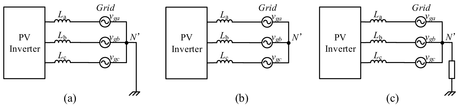
Figure 3. The grounding structure on the AC-side: (a) TN system; (b) IT system with neutral point N′ ungrounded; and (c) IT system with neutral point N′ grounded by a high-resistance resistor.
When an insulation fault occurs, the source of the fault must be identified as soon as possible to ensure system safety. As shown in Figure 4, four levels of fault locating methods are commonly investigated: system-, string-, branch-, and module-levels.
-
-
System-level fault locating determines whether faults occur on the DC- or AC-side.
-
-
String-level fault locating determines which strings (e.g., PV1 to PVn) have faults.
-
-
Branch-level fault locating determines which branches (e.g., PV11 to PV1n in the string PV1) have faults.
-
-
Module-level fault locating determines which modules (e.g., PV111 to PV11n in the branch PV11) have faults.
-
-
More details regarding fault-locating techniques can be found in section IV.
3. Ground Insulation Resistance Detection Method
This section divides insulation detection methods into two categories based on the need for additional hardware: hardware-based solutions that require additional hardware and software-based solutions that do not.
3.1. Hardware-Based Solutions
This method necessitates the integration of additional detection units into the system. There are three commonly used methods: the bridge detection unit method, the power injection method, and the self-creating ground circulation loop method.
3.1.1. Bridge Detection Unit Method
The method includes a bridge detection circuit, which can be implemented using a resistive voltage divider network. The basic idea is to change the electrical parameters in the added network using internal switches, and then use multiple electrical equations to calculate the system’s ground insulation resistance [28,29,30,31]. Notably, this additional bridge detection circuit can be installed on either the PV- or DC-bus side.
Figure 5 depicts a detailed PV system with a single-switch topology detection circuit on the PV-side, while the equivalent circuit of this system is also presented [32]. As shown in Figure 5a, resistances R1, R2, and R3 form a voltage divider network with an additional switch Sd. By turning the switch Sd on and off, two electrical equations can be obtained. Using these two equations, the system ground insulation resistance can be calculated.
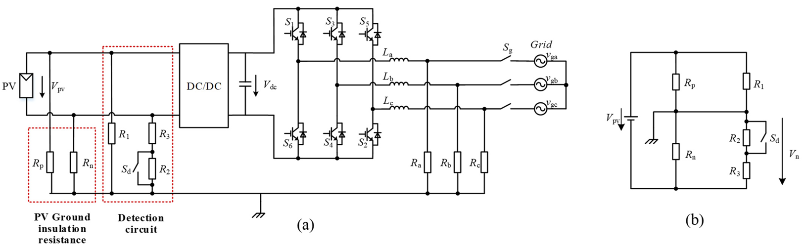
Figure 5. PV system with a single-switch topology detection circuit, (a) circuit topology, and (b) equivalent circuit.
From Figure 5b, when switch Sd is turned on, the voltage from ground to PV negative Vn(1) is obtained, as shown in Equation (1).
Similarly, when switch Sd is turned off, the voltage from PV negative to ground Vn(2) is obtained, as shown in Equation (2).
With Equation (1) and Equation (2), the ground insulation resistance (Rp and Rn) can be calculated.
Figure 6 shows alternative topologies for the detection circuit. Figure 6a depicts a topology that uses adjustable resistances rather than additional switch devices, which can reduce hardware costs [33]. Figure 6b depicts a dual-switch topology, which can enhance detection accuracy [34].
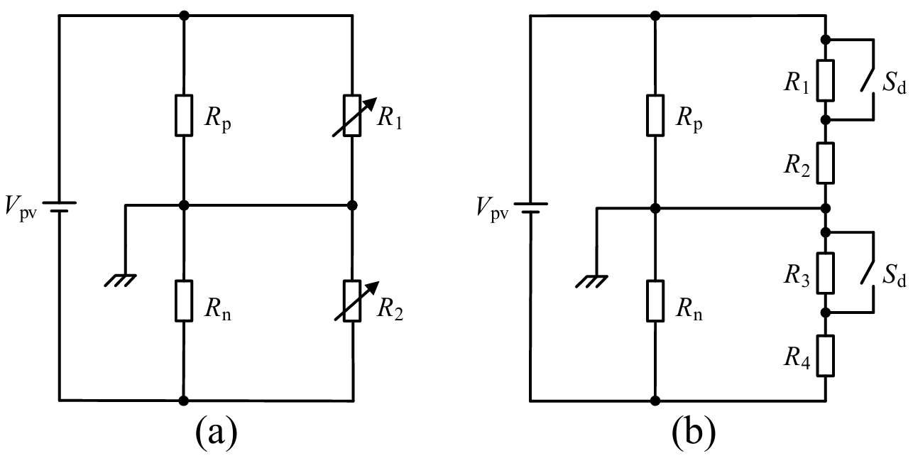
Figure 6. Alternative detection circuits, (a) adjustable resistances topology, (b) dual-switch topology.
Papers [35,36] propose a method for detecting AC-side ground insulation resistance with the same bridge detection unit, as shown in Figure 7. The basic idea is to turn on one switch at a time on the bridge arms of phases A, B, and C, then connect the corresponding AC-side ground resistance (Ra, Rb, and Rc) in parallel with Rp or Rn. As shown in Figure 7a, when S1 is turned on, Ra is connected in parallel with Rp. The equivalent circuit is presented in Figure 7b. From this, the AC-side insulation resistance Ra can be calculated using electrical equations. Similarly, by closing S3 or S5, the ground resistances of phases B and C (Rb and Rc) can also be calculated.

Figure 7. PV system with a single-switch topology detection circuit, and switch Sd is turned on, (a) circuit topology (the current path and the on-state switch S1 are highlighted in red, while the off-state switches are shown in gray), and (b) equivalent circuit.
It should be noted that real-time calculation of mathematical equations is difficult; thus, some researchers have proposed several alternative methods to address this problem [37,38]. The basic idea is to measure the detection circuit’s voltage rather than calculating its resistance. When this voltage exceeds the predetermined threshold, it indicates the presence of an insulation fault. This method has been widely used in practice.
Although the bridge detection unit method is widely employed in PV systems, there are still several limitations.
- (1)
-
Real-time calculation is difficult and requires considerable computational resources from the controller.
- (2)
-
The method is dependent on operating conditions.
3.1.2. Power Injection Method
Unlike the bridge detection unit method, this method’s detection circuit requires a voltage source and a current-limiting resistor, rather than resistor bridges. The basic idea behind this method is to perform the detection using a power signal generated by the added detection unit [39,40,41,42]. Several electrical equations are then formulated to calculate the system’s ground insulation resistance.
DC-Side Detection
Papers [43,44] propose a technique that involves installing a detection unit between the PV negative and the ground. Figure 8 shows the hardware circuit and equivalent circuit implementing this technique in a PV system. As shown in Figure 8a, a voltage signal can be injected between the PV’s negative pole and ground. In fact, this voltage signal can also be injected into the DC-bus.
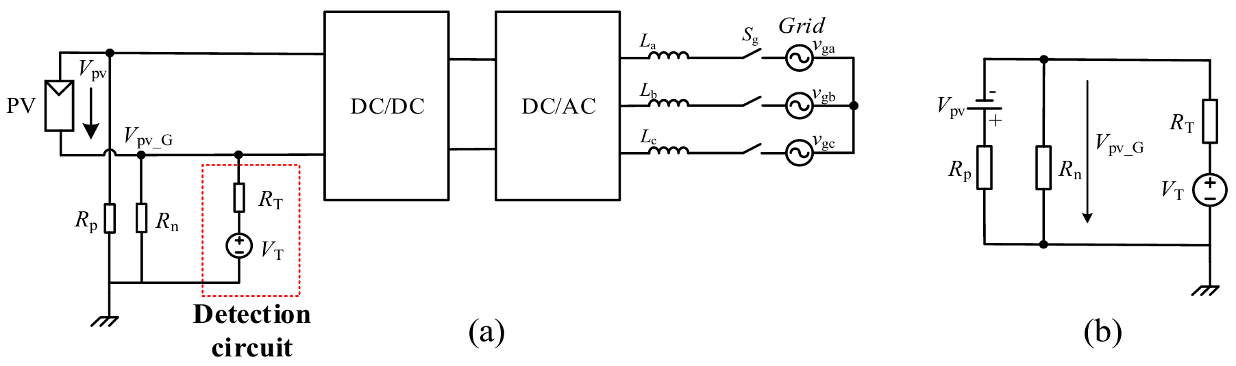
Figure 8. PV system with a detection circuit for voltage signal injection on DC-side, (a) circuit topology; and (b) equivalent circuit.
As shown in Figure 8b, to construct the electrical equations, initially set the voltage source VT to VT(1), where the subscript (1) indicates the first measurement. Then, measure the voltage of PV negative to ground and get the value VPV_G(1). Then, Equation (3) can be established.
Similarly, for the second measurement, set the voltage source VT to VT(2), where the subscript (2) indicates the second measurement. Then, measure the voltage of PV negative to ground and get the value VPV_G(2). Then, Equation (4) can be established.
With Equation (3) and Equation (4), the ground insulation resistance (Rp and Rn) can be established.
Similar to the bridge detection circuit method, the power injection method can assess insulation performance by measuring the voltage of the detection circuit [45].
AC-Side Detection
Papers [46,47] propose a method for generating a voltage signal between the virtual neutral point of the AC-side N′ and ground, with three diodes used to create the virtual neutral point N′. Figure 9 depicts the hardware circuit and equivalent circuit implementing this method in a PV system.
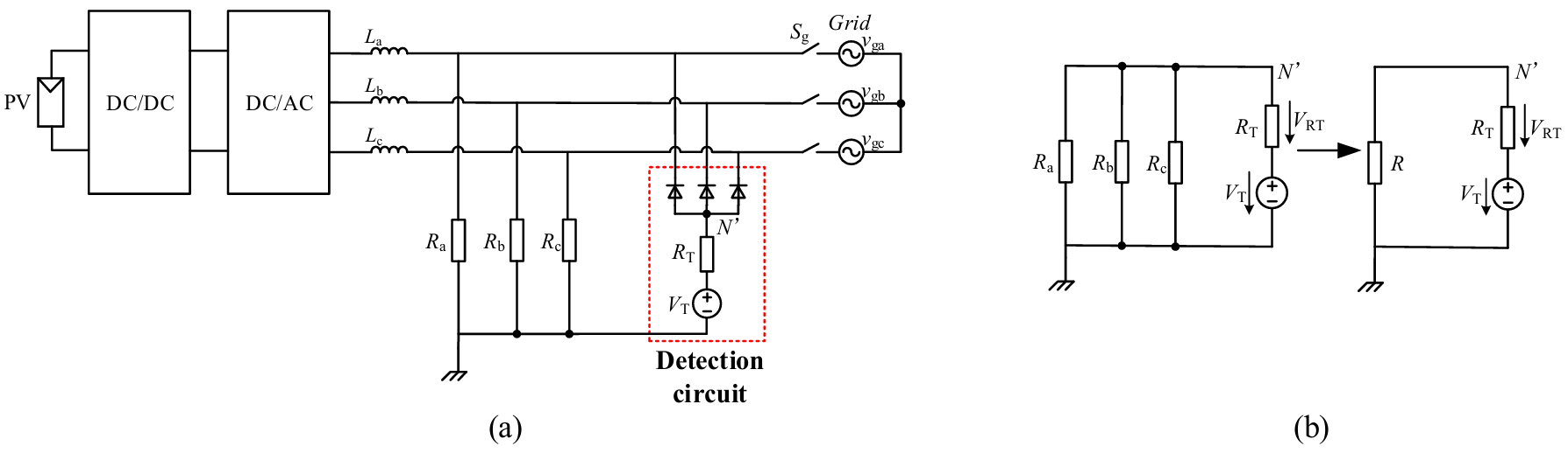
Figure 9. PV system with a detection circuit for voltage signal injection on the AC-side, (a) circuit topology; and (b) equivalent circuit.
In Figure 9b, set the voltage source as VT. Then, measure the voltage across the current-limiting resistor R and get the value VRT. Then, Equation (5) can be established.
where R is Ra//Rb//Rc.
It is worth noting that the above-described method can be used to calculate the total ground resistance of all three phases. To determine the ground resistance for each phase, detection circuits can be added separately between each phase on the AC-side and the ground [44].
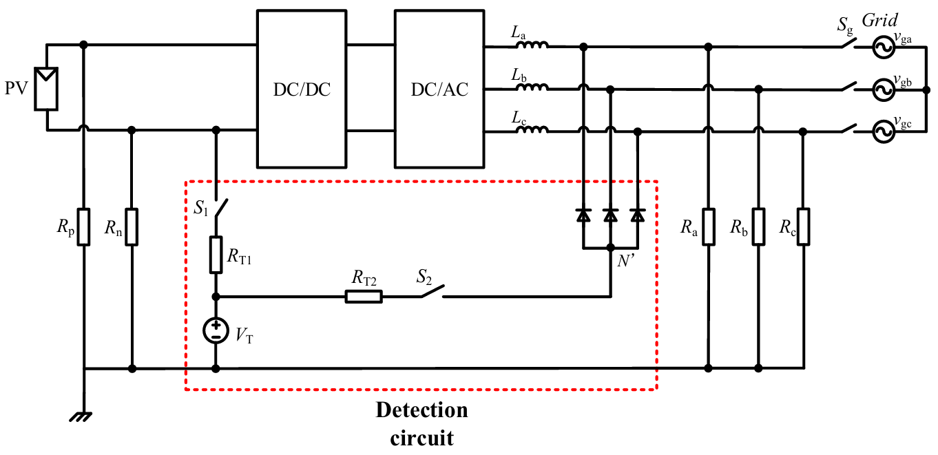
Paper [43] proposes an alternative method to reduce system costs by sharing a common voltage source VT between the DC- and AC-side. As illustrated in Figure 10, by controlling switches S1 and S2, the ground insulation resistance on the DC- and AC-side can be independently measured using the common voltage source.
It is important to note that the above-mentioned ground resistance detection method must be implemented prior to system startup; otherwise, the results may be inaccurate once operational. Therefore, papers [48,49] propose a method for measuring ground resistance while the system is operational. The topology of this system and its equivalent circuit are shown in Figure 11. From it, Vdc_equ and Vac_equ are the equivalent DC and AC voltages, respectively, and Rs is the equivalent ground resistance.
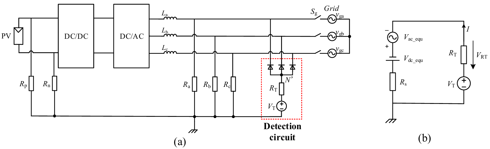
Figure 11. The method to detect the system ground resistance while in operational, (a) circuit topology, and (b) equivalent circuit.
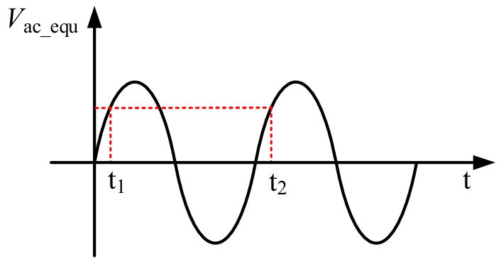
Because the AC equivalent voltage (Vac_equ) varies over time, detecting ground insulation resistance can be difficult. Therefore, a novel concept is proposed to cancel out the varying AC voltage [48,49]. Set two time points as t1 and t2, and adjust the voltage VT to two different values as VT(t1) and VT(t2). Then, at these two time points, measure the corresponding current of I as I(t1) and I(t2), as well as the voltage of RT as RT(t1) and RT(t2). Equation (6) and Equation (7) can be established.
In order to cancel out the AC voltage Vac_equ, the time interval between t1 and t2 is set to an integer multiple of AC fundamental period, as shown in Figure 12. Then, Vac_equ(t1) = Vac_equ(t2). By combining Equation (6) and Equation (7), Rs can be calculated as shown in Equation (8).
When Rs falls below the threshold, it indicates that the system ground resistance is low, causing the system to shut down. If the ground insulation resistance remains low, it is possible that an insulation fault occurred on the AC-side; otherwise, the fault is on the DC-side. This is because, when the system is turned off, the DC-side circuit is disconnected from the detection loop, making measuring the DC-side resistance impossible. Thus, only the AC-side ground resistance can be measured during this time.
The primary benefits of the power injection method are as follows.
- (a)
-
It supports both offline and online detection, which allows for continuous monitoring.
- (b)
-
It can use existing devices installed between the negative poles and ground, such as potential-induced degradation (PID) units, which lowers system costs.
However, practical limitations must be considered during implementation, particularly ensuring that the added detection unit does not interfere with normal operation. While the power injection method exhibits a negligible impact during offline execution, its online application requires strict injection signal constraints. Specifically, to reduce harmonic pollution and resonance risks, the signal frequency must not intersect with key grid harmonics or AC filter resonance points. Meanwhile, its amplitude must be limited to avoid false activation of overvoltage or overcurrent protection in the system.
3.1.3. Self-Creating Ground Circulation Loop Method
Based on the fact that leakage current increases as system insulation deteriorates, this method uses leakage current to determine ground insulation status [40,50,51,52]. To create the leakage current loop, one typical approach is to sequentially switch on the power switches originally installed in the system [53]. Electrical equations can be established using the generated leakage current loop, allowing for the calculation of ground insulation resistance. Figure 13 illustrates the grounding circulating loops when different switches are turned on.
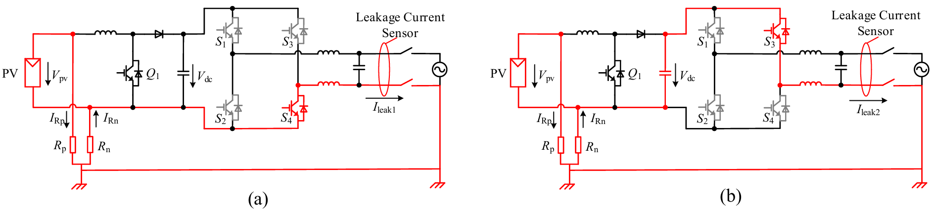
Figure 13. Single-phase system with AC-side grounding, when (a) S4 is turned on and (b) S3 is turned on.
As shown in Figure 13a, when switch S4 is turned on, ground circulating loops can be generated. It can be seen that the current flowing through Rp is IRp = Vpv/Rp, whereas the current flowing through Rn is theoretically zero. As a result, the leakage current is Ileak1 = −IRp, and Equation (9) can be established.
The method described above only detects the ground resistance Rp. To detect the ground resistance Rn, the upper switch S3 can be turned on. As shown in Figure 13b, when switch S3 is turned on, the current flowing through Rp is IRp = (Vpv − Vdc)/Rp, whereas the current flowing through Rn is IRn = Vdc/Rn. Consequently, the leakage current is Ileak2 = IRn − IRp, and Equation (10) can be established.
Furthermore, by combining Equation (9) and Equation (10), the actual values of Rp and Rn can be calculated.
It should be noted that if the grid neutral point is not grounded, the method described above cannot be applied. In this case, papers [54,55] propose a method that involves adding a detection unit between the AC- or DC-side and ground. Similarly, by turning on the appropriate switch, a ground circulating loop can be created. Then, the electrical equation is established to calculate the ground insulation resistance.
Figure 14 shows the added detection unit installed between the DC-side and ground. The added unit connects the PV positive or negative pole to ground via switches K1 and K2.
When K1 is turned on, as shown in Figure 14a, the current IRn = Vpv/(Rn + RT). When K2 is turned on, as shown in Figure 14b, the current IRp = Vpv/(Rp + RT). By combining these two equations, Rp and Rn can be calculated.

Figure 14. Self-creating active ground circulation loop via a DC-side detection unit under different switch states: (a) loop with K1 is turned on, (b) loop with K2 is turned on.
From above, this method is simple to implement and has a quick response time, allowing it to detect serious insulation faults such as ground short circuits. The primary technical challenge is that the system’s distributed capacitor can cause capacitive leakage current, which can be combined with resistive leakage current. This interference may reduce the accuracy of insulation detection.
3.2. Software-Based Solutions
In contrast to hardware-based solutions, software-based solutions do not require any additional detection units. Instead, system electrical parameters are monitored and observed to detect insulation resistance [56,57,58,59,60,61,62,63,64,65].
3.2.1. Current Judgment Method
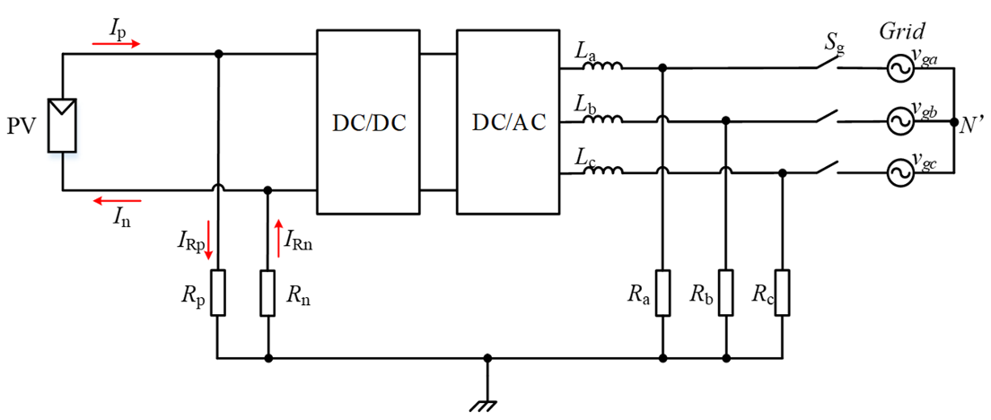
This method determines the insulation state by measuring the sum of currents at the positive and negative poles on the DC-side. When the PV system is operating normally, as shown in Figure 15, the sum of currents Ip and In is nearly zero [59,60]. However, if there is a ground fault on the DC-side, some current will flow into the ground, resulting in positive and negative imbalances and a significant increase in the current sum [61].
There are two limitations to this method: (1) It cannot determine whether the fault is located at the positive or negative pole. (2) It is ineffective when ground insulation faults occur at both the positive and negative poles.
3.2.2. Ground Voltage Judgment Method
This method enables ground insulation monitoring based on ground voltage on either the DC- or AC-side. The basic principle is that when a ground fault occurs, the ground voltage shifts, allowing for monitoring.
DC-Side Detection
Figure 16 shows the ground voltage in a PV system. Ideally, the ground voltages across Rp and Rn should be equal, with Vpv+G = Vpv−G. However, when an insulation fault occurs, ground voltage shifting may occur. Specifically, as Rp decreases, Vpv+G decreases while Vpv−G increases, and vice versa. As a result, monitoring ground voltages can be used to determine whether an insulation fault exists at a specific PV pole [62].
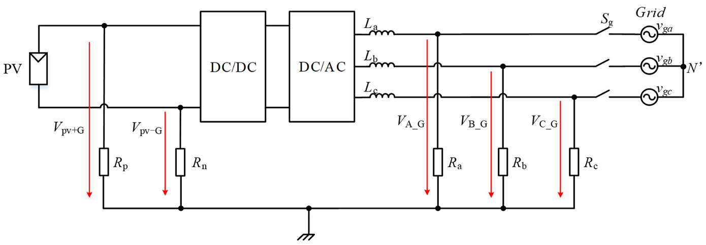
AC-Side Detection
Similarly, the ground voltages VA_G, VB_G, and VC_G for AC phases A, B, and C should ideally be equal. When a ground fault occurs in one phase, the ground voltage of the faulty phase drops to almost zero, while the ground voltage of the non-faulty phase increases. Based on this feature, monitor the ground voltages of each phase in real time and compare them to the threshold. As a result, it can determine whether a ground fault has occurred on the AC-side [63].
According to the analysis above, one advantage of this method is its ability to identify whether faults occur at the positive or negative poles. However, this method is unable to detect symmetrical insulation faults, such as concurrent ground faults on both PV poles or all three AC phases. Furthermore, its performance is affected by system operating conditions. The AC-side load imbalance, in particular, reduces its sensitivity to early-stage faults, resulting in missed or false alarms.
3.2.3. Voltage and Current Joint-Judgment Method
In addition to monitoring insulation via current or ground voltage, these two parameters can be combined to calculate the ground insulation resistance in the system [64].
Figure 17 depicts an alternative solution for monitoring leakage current and DC-bus voltage. First, measure the ground voltage of the DC-bus negative Vdc_G, as well as the system’s leakage current Ileak. Then, Vdc_G and Ileak are filtered to remove high-frequency signals, yielding DC components Vdc_G(DC) and Ileak(DC). Therefore, the ground insulation resistance Rn is calculated with the equation of Rn = Vdc_G(DC) × K/Ileak(DC). In the equation, K is the adjustment factor, which is used to correct the shunt effect of Rp on the leakage current.
When calculating total ground insulation resistance on the AC-side, the three-phase power grid is equivalent to a voltage source. R represents the load between the voltage source to ground, and the current flowing through it is Ileak(DC). Because the positive pole of this voltage source is at the same potential as the midpoint of the DC-bus, the voltage from the positive pole to ground equals Vdc/2 + Vdc_G(DC). Thus, the resistance R can be calculated as R = (Vdc/2 + Vdc_G(DC))/Ileak(DC).
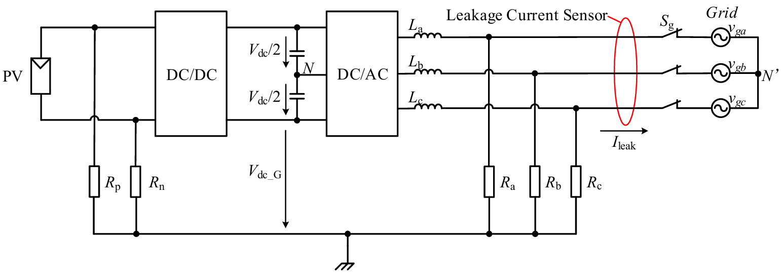
Furthermore, this method can assess insulation status by tracking dynamic changes in Vdc_G(DC) and Ileak(DC). When these parameters exceed their associated thresholds, it indicates that the system has an insulation fault.
3.2.4. Capacitance Voltage Judgment Method
Since the system’s existing safety capacitors and ground insulation resistance form an RC current loop, the changes in insulation resistance can affect capacitor voltage. As a result, this method monitors the insulation status by measuring the voltage variation of the capacitor [65].
Figure 18 shows a PV system with a filter, where the safety capacitors C1 and C2 are installed between the positive and negative poles and the ground. Since C1 and C2 are connected in parallel with Rp and Rn physically, resulting in an RC loop.
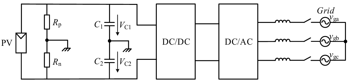
When the insulation status is normal, both Rp and Rn are extremely high, resulting in a large time constant (τ = R × C) for the circuit loop. Under these conditions, the capacitor voltages VC1 and VC2 remain nearly constant between adjacent sampling intervals. However, if an insulation fault occurs, the decrease of Rp and Rn reduces the time constant τ, causing observable changes in VC1 and VC2 [65]. By monitoring the voltage values VC1 and VC2 in real time and assessing whether their variations between consecutive sampling intervals exceed a threshold, it is possible to detect changes in Rp and Rn and thus identify insulation faults.
It should be noted that this method only provides preliminary information on whether the ground insulation resistance has changed. Specific fault detection requires further evaluation in conjunction with other methods.
3.3. Detection Methods Evaluation
Table 1 presents the evaluation of different methods, including the dimensions of detection range, operating mode, impact on the system, limitations, and cost.
The table indicates that the self-creating ground circulation loop method, the current judgment method, and the capacitance voltage judgment method are primarily utilized for insulation detection on the DC-side, whereas the other methods can be applied to insulation detection on both the DC- and AC-side. Among these methods, the bridge detection unit method is primarily used for offline detection, the voltage and current joint-judgment method is used for online detection, while the others can be employed in both offline and online modes.
Furthermore, these methods exhibit certain limitations. Among hardware-based solutions, the bridge detection unit method poses challenges for real-time calculation. The power injection method limits the frequency and amplitude of the injected signal during online operation to avoid interference with normal system function. Furthermore, capacitive leakage current may have a negative impact on the effectiveness of the self-creating ground circulation loop method. It is important to note that all methods are influenced by the environment. Most methods rely on the PV array’s operating voltage, which severely limits their functionality at night or in low light conditions. Under these conditions, the power injection method with its own excitation source continues to be operational. However, all methods encounter difficulties during rapid irradiance transients, as the resulting voltage fluctuations can introduce significant measurement noise.
In terms of hardware costs, both the bridge detection unit method and the self-creating ground circulation loop method have low-cost, requiring only a few resistors and switches. The cost of the power injection method varies based on implementation. Using a dedicated detection circuit can be costly, but reusing the existing PID recovery equipment can significantly reduce the cost. Furthermore, all software-based solutions have extremely low hardware costs because they do not require additional hardware components.
In practical applications, factors such as system operating conditions, detection accuracy requirements, and cost should all be taken into account when determining the most effective detection method.
Table 1. Evaluation of different methods.
|
Method |
Detection Range |
Operating Mode |
Impact on the System |
Limitations |
Cost |
|
|---|---|---|---|---|---|---|
|
Hardware-based solutions |
Bridge detection unit method |
DC- and AC-side |
Offline |
Implement only during system startup |
Real-time calculation difficult |
Low |
|
Power injection method |
DC- and AC-side |
Online and Offline |
Injecting power signal |
Online implementation requires constrained signal injection to prevent interference |
Variable |
|
|
Self-creating ground circulation loop method |
DC-side |
Online and Offline |
No impact |
Sensitive to capacitive leakage current |
Low |
|
|
Software-based solutions |
Current judgment method |
DC-side |
Online and Offline |
No impact |
Cannot tell which pole has the fault and blind to dual-pole fault |
Extremely low |
|
Ground voltage judgment method |
DC- and AC-side |
Online and Offline |
Susceptible to three-phase imbalance, and blind to symmetric faults |
|||
|
Voltage and current joint-judgment method |
DC- and AC-side |
Online |
Filtering process needs to be carried out |
|||
|
Capacitance voltage judgment method |
DC-side |
Online and Offline |
Limited to preliminary assessment |
|||
4. Insulation Fault Locating
This section discusses insulation fault locating technologies at the system-, string-, branch-, and module-levels [66,67,68,69,70,71,72,73,74,75,76,77,78,79,80,81,82,83].
4.1. System-Level Fault Locating
The system-level fault locating is designed to determine whether the fault is on the DC- or AC-side of the system.
Paper [73] proposed a system-level fault locating method, which analyzes frequency-domain characteristics of DC-bus ground voltages.
Figure 19 shows the ground voltage at the DC-bus in a PV system. In general, the DC-bus positive ground voltage Vdc+G and DC-bus negative ground voltage Vdc−G have a relatively large DC component, while the AC component is relatively small. When an insulation fault occurs on either DC-side pole, the corresponding ground voltage approaches 0. As a result, the DC component of the corresponding ground voltage is close to zero. Thus, the DC components of the DC-bus ground voltage can be used to identify DC-side faults.
If there is an insulation fault on the AC-side, the leakage current will couple to the DC-side, resulting in a significant AC component in the DC-bus ground voltage. Thus, the AC components of ground voltage can be used to identify an AC-side fault.
From above, Figure 20 depicts the whole process of system-level fault locating. The general idea is that if the DC component of the DC-bus ground voltage is less than the threshold, it is assumed that an insulation fault exists on the DC-side. If the AC component in the DC-bus ground voltage exceeds the threshold, the fault can be identified as being on the AC-side.

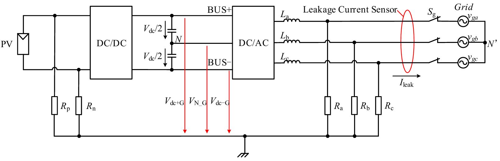
Alternatively, paper [74] proposes another fault locating method that involves measuring ground voltage at the DC-bus midpoint, VN_G. Figure 21 illustrates the detailed fault locating process of this method.
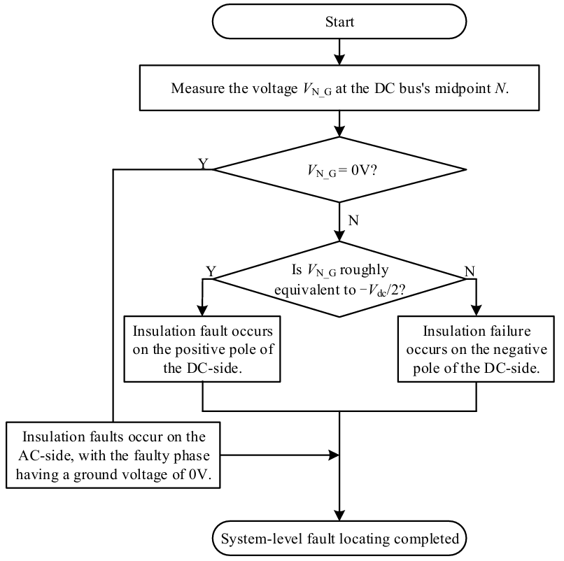
In normal operation, the DC-bus midpoint N and the AC-side neutral point N′ remain at the same potential, and the ground voltage VN_G is typically 0 V. However, if there is an insulation fault on DC-side, the ground voltages at the positive and negative poles are not equal, resulting in a voltage shift at DC-bus midpoint. If a ground fault occurs on the positive pole of the DC-bus, the ground voltage VN_G is shifted to −Vdc/2. In contrast, when a ground fault occurs at the negative pole, the ground voltage VN_G is shifted to +Vdc/2.
Furthermore, when one of the three AC phases experiences a ground fault, the ground voltage for that phase is zero. However, it does not affect the ground voltage of the DC-bus midpoint, VN_G.
As a result, if the ground voltage at the midpoint deviates significantly from 0, an insulation fault on the DC-side is identified, which can be classified as a positive or negative pole fault based on the detailed voltage offset. Otherwise, it is determined that the insulation fault exists on the AC-side. The faulty phase is then identified by analyzing each phase’s ground voltage.
4.2. String-Level Fault Locating
Figure 22 shows a PV system with multiple PV strings connected in parallel to the DC-bus. In order to achieve string-level fault locating, two typical locating methods are introduced: the string-by-string fault locating method and the perturbation and observation method.
4.2.1. String-by-String Fault Locating Method
Papers [45,75,76] propose a method for carrying out string-by-string fault locating. The key to this method is to connect only one PV string to the system at a time, isolating the others.
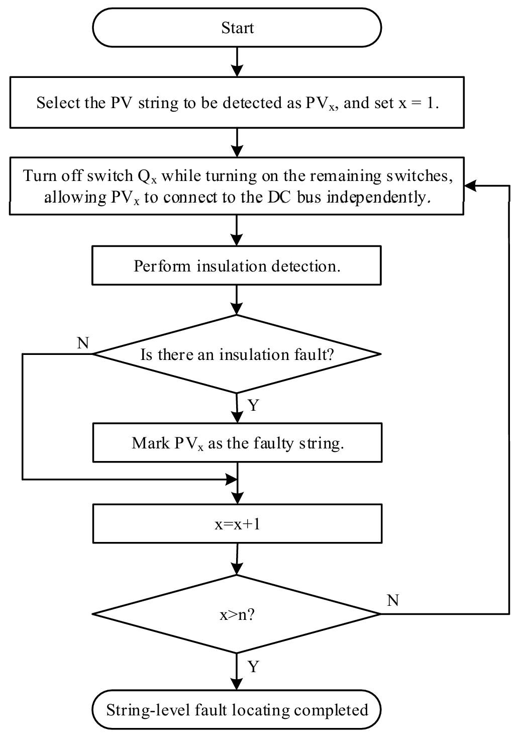
Figure 23 presents a detailed example. To check string PV1, turn off the corresponding Boost switch Q1. Also, turn on switches in the rest of the strings (Q2, …, Qn) simultaneously. As a result, the remaining PV strings (PV2, …, PVn) are separated from the system. Then, measure the system’s ground resistance, which is considered the ground resistance for string PV1. Similarly, other strings can be checked in the same way. Figure 24 depicts the entire procedure for all the strings. From above, this method has the advantage of accurately locating all insulation fault strings. However, the locating time may take a while.
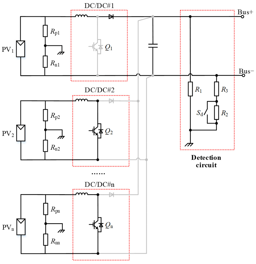
Figure 23. The hardware architecture for fault locating in the case of multiple PV strings connected in parallel.
4.2.2. Perturbation and Observation Method
This method involves applying voltage perturbations to each PV string and analyzing the system’s response to these perturbations to locate insulation faults.
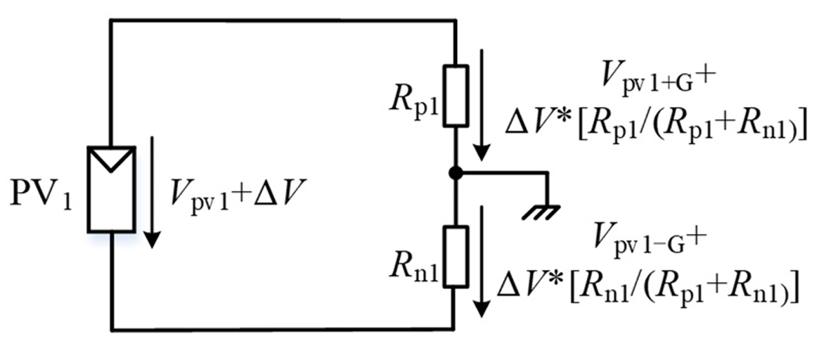
Figure 25 depicts the voltage and current in a PV system with multiple PV strings. Figure 26 depicts the scenario in which a voltage perturbation is applied to PV1. When the output voltage Vpv1 changes by ΔV, the ground voltage of the positive pole changes by ΔVp = ΔV∗[Rp1/(Rp1 + Rn1)], while the ground voltage of the negative pole changes by ΔVn = ΔV∗[Rn1/(Rp1 + Rn1)]. If string PV1 is properly insulated, the ground insulation resistances Rp1 and Rn1 are equivalent. Thus, ΔVp equals ΔVn. Otherwise, if there are insulation faults in string PV1, the ground insulation resistances of the positive and negative poles will be different. This can result in significant differences in ΔVp and ΔVn [77].
In order to implement perturbations in practice, PV I-V scanning is normally applied together. As a result, the fault locating process begins by adjusting the operating point on the I-V curve, which causes a change in the PV string’s output voltage. Then, the difference between ΔVp and ΔVn is measured [78]. Repeat this process for each PV string. If the difference between ΔVp and ΔVn in a specific string exceeds the threshold, it indicates an insulation failure in this string.
Furthermore, paper [79] proposes a perturbing method, which is applied to each string’s ground voltage and then monitors the leakage current to find the insulation fault. When an insulation fault occurs in a PV string, a low-resistance path is formed between the fault point and ground. If the string’s ground voltage changes, additional fault current flows through the ground path, causing a significant change in system leakage current. As a result, measuring the system’s leakage current while varying the ground voltage can aid in locating the fault.
4.3. Branch-Level Fault Locating
This section introduces branch-level fault locating. Taking string PV1 in the PV system as an example, Figure 27 depicts the detailed branch structure. From it, the string PV1 is made up of multiple PV branches PV11 to PV1n connected in parallel.
Papers [80,81,82] propose a fault locating method based on leakage current changes across branches. The principle is based on the idea that the value and direction of leakage current for faulty branches differ from normal conditions.
The following uses PV11 ground fault as an example. Under normal conditions (see Figure 27a), all leakage currents flow in the same direction and have the same values for all branches.
In faulty conditions (see Figure 27b), the normal branches’ Ileak2~Ileakn direction is the same as in normal conditions. In contrast, the current Ileak1 of the faulty branch equals the sum of all other branch leakage currents, which is significantly greater than that in normal conditions. In addition, the current Ileak1 flows in the opposite direction than it would in normal operation.
Based on this, the faulty branch can be identified by examining the leakage current values and directions of each branch.
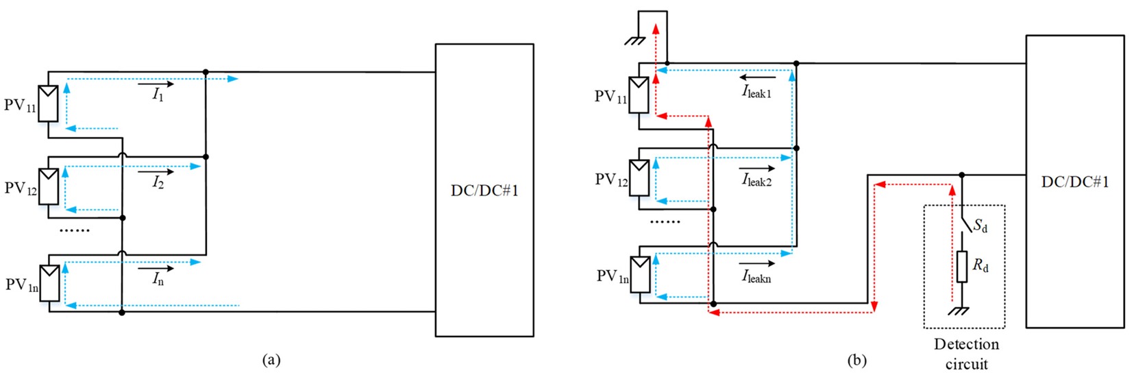
Figure 27. The current paths of each PV branch, (a) normal conditions (blue lines), (b) faulty conditions (red line for the faulty branch, blue lines for normal branches).
4.4. Module-Level Fault Locating
This section discusses module-level fault locating. Papers [78,83] propose a method for precisely locating the faulty module based on ground voltage distribution characteristics.
Figure 28 depicts the module-level structure of branch PV11 in the PV system. When an insulation fault occurs in a PV module, its potential approaches ground potential, resulting in a significant change in the ground voltage distribution in the PV branch. The details are as follows.
From Figure 28, Equation (11) can be obtained.
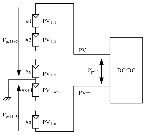
Assume the #x module is faulty to the ground, the location #x can be determined with Equation (12).
It’s worth noting that the method described above is only effective for single-point faults in PV modules. Furthermore, external thermal imaging and electroluminescence imaging technologies can be used together to locate multiple-point faults [84].
4.5. Fault Locating Methods Evaluation
Table 2 summarizes the characteristics of each locating method. System-level fault locating is simple to implement and inexpensive. The string-by-string fault locating method can be used to locate multiple faults, but it is slow. The perturbation and observation method is also easy to implement. Branch-level fault locating and module-level fault locating are only applicable to single-point faults.
Furthermore, in order to select an economical and efficient locating strategy in practical applications, several factors must be considered, including system scale, operating conditions, and maintenance needs.
Table 2. Summary of fault locating methods.
|
Dimension |
Method |
Characteristics |
|---|---|---|
|
System-level |
Locating method based on ground voltage |
Simple to implement and low-cost |
|
String-level |
String-by-string fault locating method |
Multi-point fault locating, and long locating time |
|
Perturbation and observation method |
Simple to implement and low-cost |
|
|
Branch-level |
Locating method based on the value and direction of leakage current |
Single-point fault locating |
|
Module-level |
Locating method based on ground voltage distribution characteristics |
Single-point fault locating |
5. Conclusions
This paper provides a systematic review of key technologies for detecting insulation resistance and locating faults in PV systems. Two types of insulation resistance detection methods are presented: hardware-based solutions and software-based solutions. The hardware-based solutions include the bridge detection unit method, power injection method, and self-creating ground circulation loop method. The software-based solutions are the current judgment method, ground voltage judgment method, voltage and current joint-judgment method, and capacitance voltage judgment method. For summarized methods, the detection range, operating mode, impact on the system, and limitations are all considered.
Following that, fault locating methods at the system-, string-, branch-, and module-levels are discussed. The system-level fault locating method determines whether the fault is on the DC- or AC-side by measuring ground voltage. String-level fault locating is divided into two methods: the string-by-string fault locating method and the perturbation and observation method. Branch-level fault locating is based on the value and direction of leakage current. The module-level fault locating method uses ground voltage distribution characteristics to identify the faulty PV module.
Future research can be conducted in the following directions. (1) Develop a low-cost online insulation detection method that meets the requirements for real-time performance, cost-effectiveness, and large-scale deployment in renewable energy scenarios. (2) Use artificial intelligence technology to reduce false alarms caused by noise interference and environmental changes, improving the accuracy of detection methods in complex scenarios. (3) Develop an intelligent locating method capable of collaborative fault locating at multiple levels and faults, allowing for quick and accurate fault isolation.
Statement of the Use of Generative AI and AI-Assisted Technologies in the Writing Process
Generative AI was used solely for English grammar polishing.
Acknowledgments
The authors would like to thank the Technical Development Center of Ginlong Technologies Co., Ltd. for their technical assistance and access to the specialized database.
Author Contributions
Conceptualization, W.Z. and L.X.; Methodology, W.Z. and L.X.; Formal Analysis, W.Z.; Investigation, W.Z. and L.X.; Resources, Y.W. (Yiming Wang 1) and P.X.; Data Curation, Y.W. (Yiming Wang 2); Writing—Original Draft Preparation, W.Z. and L.X.; Writing—Review & Editing, W.Z., L.X., Y.W. (Yiming Wang 1), Y.W. (Yiming Wang 2) and K.M.; Visualization, W.Z. and L.X.; Supervision, W.Z., P.X. and K.M.; Project Administration, Y.W. (Yiming Wang 1) and P.X.; Funding Acquisition, Y.W. (Yiming Wang 1).
Ethics Statement
Not applicable.
Informed Consent Statement
Not applicable.
Data Availability Statement
Data availability is not applicable to this paper as no new data were created or analyzed in this study.
Funding
This work was funded by National Key R&D Program of China (2024YFB3814000) and R&D Program of Zhejiang (2024C01242(SD2)).
Declaration of Competing Interest
The authors declare that they have no known competing financial interests or personal relationships that could have appeared to influence the work reported in this paper.
References
- Hong YY, Pula RA. Methods of photovoltaic fault detection and classification: A review. Energy Rep. 2022, 8, 5898–5929. doi:10.1016/j.egyr.2022.04.043. [Google Scholar]
- Arévalo P, Benavides D, Tostado-Véliz M, Aguado JA, Jurado F. Smart monitoring method for photovoltaic systems and failure control based on power smoothing techniques. Renew. Energy 2023, 205, 366–383. doi:10.1016/j.renene.2023.01.059. [Google Scholar]
- Ren B, Chi Y, Zhou N, Wang Q, Wang T, Luo Y, et al. Machine learning applications in health monitoring of renewable energy systems. Renew. Sustain. Energy Rev. 2024, 189, 114039. doi:10.1016/j.rser.2023.114039. [Google Scholar]
- Lokanath SV, Skarbek B, Schindelholz EJ. Degradation Processes and Mechanisms of PV Wires and Connectors. In Durability and Reliability of Polymers and Other Materials in Photovoltaic Modules; William Andrew Publishing: Norwich, NY, USA, 2019; pp. 217–233. [Google Scholar]
- Anagha ER, Kulkarni SV, Shiradkar N. Development of a characterization technique to effectively detect latent insulation defects in the field-deployed PV modules. Sol. Energy Mater. Sol. Cells 2025, 292, 113761. doi:10.1016/j.solmat.2025.113761. [Google Scholar]
- Miller DC, Arnold RL, Hacke PL, Jiang CS, Hayden SC, Moutinho H, et al. Photovoltaic Cable Connectors: A Comparative Assessment of the Present State of the Industry. IEEE J. Photovolt. 2024, 14, 793–802. doi:10.1109/JPHOTOV.2024.3414178. [Google Scholar]
- Abdelrahman MS, Hussein HM, Kharchouf I, Rafin SMSH, Mohammed OA. Digital Twin-Based Approach for Monitoring and Event Detection in PV Systems. In Proceedings of the 2024 IEEE International Conference on Environment and Electrical Engineering and 2024 IEEE Industrial and Commercial Power Systems Europe (EEEIC/I&CPS Europe), Rome, Italy, 17–20 June 2024. [Google Scholar]
- Melios C, Dimitriou A, Androvitsaneas VP, Gonos IF, Charalambous CA. Determining the Insulation Resistance of DC Cables Used in Photovoltaic Systems Under Operational Conditions. IEEE Trans. Ind. Appl. 2022, 58, 6931–6941. doi:10.1109/TIA.2022.3192736. [Google Scholar]
- Demetriou A, Buxton D, Charalambous CA. Stray Current DC Corrosion Blind Spots Inherent to Large PV Systems Fault Detection Mechanisms: Elaboration of a Novel Concept. IEEE Trans. Power Deliv. 2018, 33, 3–11. doi:10.1109/TPWRD.2016.2538789. [Google Scholar]
- Roy S, Alam MK, Khan F, Johnson, Flicker J. An irradiance-independent, robust ground-fault detection scheme for PV arrays based on spread spectrum time-domain reflectometry (SSTDR). IEEE Trans. Power Electron. Aug. 2018, 33, 7046–7057. doi:10.1109/TPEL.2017.2755592. [Google Scholar]
- Buerhop C, Stroyuk O, Pickel T, Hauch J, Peters IM. Evolution of inverter ground impedances for PV modules with various backsheet types. Prog. Photovolt. Res. Appl. 2023, 31, 1161–1169. doi:10.1002/pip.3621. [Google Scholar]
- Guerrero JM, Serrano-Jiménez D, Valiño V, Blázquez-Campanón A, Navarro G, Platero CA. AC Ground Fault Location Method Through Voltage Frequency Components Analysis for Variable Speed Drives. IEEE Trans. Ind. Appl. 2024, 60, 8845–8855. doi:10.1109/TIA.2024.3429448. [Google Scholar]
- Dhar S, Patnaik RK, Dash PK. Fault Detection and Location of Photovoltaic Based DC Microgrid Using Differential Protection Strategy. IEEE Trans. Smart Grid.Sept. 2018, 9, 4303–4312. doi:10.1109/TSG.2017.2654267. [Google Scholar]
- Araneo R, Mitolo M. Insulation Resistance and Failures of a High-Power Grid-Connected Photovoltaic Installation: A Case Study. IEEE Ind. Appl. Mag. 2021, 27, 16–22. doi:10.1109/MIAS.2020.3024490. [Google Scholar]
- Hernández JC, Vidal PG, Medina A. Characterization of the insulation and leakage currents of PV generators: Relevance for human safety. Renew. Energy 2010, 35, 593–601. doi:10.1016/j.renene.2009.08.006. [Google Scholar]
- Lee KY, Lim ST, Chae DJ, Kim DW, Lim YB, Ryu IH. Study on the Development of Measurement Technology for Direct Current Power Systems in Insulation State Using AHRD Algorithm. J. Electr. Eng. Technol. 2020, 15, 2387–2394. doi:10.1007/s42835-020-00496-5. [Google Scholar]
- Venkatakrishnan GR, Rengaraj R, Tamilselvi S, Harshini J, Sahoo A, Saleel CA, et al. Detection, location, and diagnosis of different faults in large solar PV system—A review. Int. J. Low-Carbon Technol. 2023, 18, 659–674. doi:10.1093/ijlct/ctad018. [Google Scholar]
- Li Q, Li Q, Wang L, Wu Q, Qin G, Zhang H, et al. Improving the accuracy of insulation resistance measurements of a single arm unbalanced bridge using a parameter matching design and filtering algorithm for battery packs used in electric ships. Measurement 2022, 195, 111133. doi:10.1016/j.measurement.2022.111133. [Google Scholar]
- Melios C, Dimitriou A, Androvitsaneas VP, Gonos IF, Charalambous CA. Determining the Dynamic Insulation Resistance of DC Cables Used in Photovoltaic Systems under Operational Conditions. In Proceedings of the 2021 IEEE International Conference on Environment and Electrical Engineering and 2021 IEEE Industrial and Commercial Power Systems Europe (EEEIC/I&CPS Europe), Bari, Italy, 7–10 September 2021. [Google Scholar]
- Yang B, Wang J, Zhang X, Zhang M, Shu H, Li S, et al. MPPT design of centralized thermoelectric generation system using adaptive compass search under non-uniform temperature distribution condition. Energy Convers. Manag. 2019, 199, 111991. doi:10.1016/j.enconman.2019.111991. [Google Scholar]
- Hu Y, Cao W, Ji B, Si J, Chen X. New multi-stage DC–DC converters for grid-connected photovoltaic systems. Renew. Energy 2015, 74, 247–254. doi:10.1016/j.renene.2014.08.009. [Google Scholar]
- Alexandru C. Simulation and Optimization of a Dual-Axis Solar Tracking Mechanism. Mathematics 2024, 12, 1034. doi:10.3390/math12071034. [Google Scholar]
- Zhang X, Yang B, Yu T, Jiang L. Dynamic Surrogate Model Based Optimization for MPPT of Centralized Thermoelectric Generation Systems Under Heterogeneous Temperature Difference. IEEE Trans. Energy Convers. 2020, 35, 966–976. doi:10.1109/TEC.2020.2967511. [Google Scholar]
- Mitolo M, Tartaglia M, Panetta S. Of International Terminology and Wiring Methods Used in the Matter of Bonding and Earthing of Low-Voltage Power Systems. In Proceedings of the 2009 IEEE Industry Applications Society Annual Meeting, Houston, TX, USA, 4–8 October 2009. [Google Scholar]
- Ogundiran YL, Griffo A, Wang J, Sundeep S, Bruder-Mandler F, Groh T. Insulation Monitoring in Ungrounded Electrical System for More Electric Aircrafts. In Proceedings of the 2023 IEEE Workshop on Electrical Machines Design, Control and Diagnosis (WEMDCD), Newcastle upon Tyne, UK, 13–14 April 2023. [Google Scholar]
- Bidram A, Reno MJ, Abadi SAGK, Aparicio MJ, Bauer D. Trends in dc Microgrids: From the control and protection perspective. IEEE Electrif. Mag. 2024, 12, 33–47. doi:10.1109/MELE.2024.3385978. [Google Scholar]
- Buberger J, Hohenegger M, Estaller J, Wiedenmann A, Grupp W, Bliemetsrieder W, et al. Bidirectional Charging for BEVs with Reconfigurable Battery Systems via a Grid-Parallel Proportional-Resonant Controller. Electricity 2023, 4, 171–184. doi:10.3390/electricity4020011. [Google Scholar]
- Liu Y-C, Lin C-Y. Insulation Fault Detection Circuit for Ungrounded DC Power Supply Systems. In Proceedings of the SENSORS, 2012 IEEE, Taipei, China, 28–31 October 2012. [Google Scholar]
- Li Z, Cui X, He Z, Li E, Wang Y. A novel method for electric vehicle insulation detection based on the extended Kalman filter algorithm. Measurement 2024, 229, 114419. doi:10.1016/j.measurement.2024.114419. [Google Scholar]
- Zhao C, Jia X, Hao Z. The New Method of Monitoring DC System Insulation Online. In Proceedings of the IECON’01. 27th Annual Conference of the IEEE Industrial Electronics Society (Cat. No.37243), Denver, CO, USA, 29 November–2 December 2001. [Google Scholar]
- Chen Z, Cui W, Cui X, Qiao H, Lu H, Qiu N. A New Method of Insulation Detection on Electric Vehicles Based on a Variable Forgetting Factor Recursive Least Squares Algorithm. IEEE Access 2021, 9, 73590–73607. doi:10.1109/ACCESS.2021.3079332. [Google Scholar]
- Huawei Digital Power Technologies Co., Ltd. Insulation Impedance Detection Circuit and Method, and Power Supply Device. CN Patent 116068276A, 5 May 2023. [Google Scholar]
- Huawei Digital Power Technologies Co., Ltd. Insulation Detection Device and Insulation Detection Circuit. CN Patent 109031058B, 18 December 2018. [Google Scholar]
- Huawei Digital Power Technologies Co., Ltd. An Insulation Detection Circuit. CN Patent 117214639A, 12 December 2023. [Google Scholar]
- Tongji University. An Online Insulation Monitoring Method for Electric Vehicle High-Voltage Power. CN Patent 102841284B, 26 December 2012. [Google Scholar]
- Huawei Technologies Co., Ltd. Cable Insulation Impedance Detection Method and Device. WO Patent WO2021/213211A1, 28 October 2021. [Google Scholar]
- Huawei Technologies Co., Ltd. Inverter and Insulation Detection Circuit. CN Patent 110927457B, 27 March 2020. [Google Scholar]
- Jiang JS, Ji H. Study of Insulation Monitoring Device for DC System Based on Multi-Switch Combination. In Proceedings of the 2009 Second International Symposium on Computational Intelligence and Design, Changsha, China, 12–14 December 2009. [Google Scholar]
- Liu Y, Chang E, Lee Y. Detection of Ground Insulation Faults in Ungrounded DC Power Supply Systems by Using a DC Current Injection Method. Energy Procedia 2019, 156, 349–355. doi:10.1016/j.egypro.2018.11.154. [Google Scholar]
- Wu Y, Zhang P. A Novel Online Monitoring Scheme for Underground Power Cable Insulation Based on Common-Mode Leakage Current Measurement. IEEE Trans. Ind. Electron. 2022, 69, 13586–13596. doi:10.1109/TIE.2022.3142434. [Google Scholar]
- Stipetić N, Filipović-Grčić B, Uglešić I, Xémard A, Andres N. Earth-fault detection and localization in isolated industrial MV network—Comparison of directional overcurrent protection and signal injection method. Electr. Power Syst. Res. 2021, 197, 107313. doi:10.1016/j.epsr.2021.107313. [Google Scholar]
- Zhu G, Zhou K, Lu L, Li Y, Xi H, Zeng Q. Online Monitoring of Power Cables Tangent Delta Based on Low-Frequency Signal Injection Method. IEEE Trans. Instrum. Meas. 2021, 70, 3514108. doi:10.1109/TIM.2021.3069020. [Google Scholar]
- Sungrow Power Supply Co., Ltd. A Photovoltaic Inverter, Photovoltaic Power Generation System and Control Method Thereof. CN Patent 118054686A, 17 May 2024. [Google Scholar]
- Sungrow Power Supply Co., Ltd. Inverter and Method for Detecting Insulation Impedance of Inverter. EP Patent 4293375A1; US Patent 2023/0400489A1, 14 December 2023. [Google Scholar]
- Ginlong Technologies Co., Ltd. A String Photovoltaic System Insulation Detection Method, Device and Electronic Equipment. CN Patent 117240214A, 15 December 2023. [Google Scholar]
- Sungrow Power Supply Co., Ltd. An AC Insulation Detection Circuit, System and Method. CN Patent 107748292B, 24 March 2020. [Google Scholar]
- Wang L, Li L, Fan L, Nan J, Xu K, Huo Y, et al. Research on the Insulation Detection Technology of the AC Cable in Distributed Photovoltaic Power Station Considering Photovoltaic Inverter. In Proceedings of the 2022 2nd International Conference on Electrical Engineering and Mechatronics Technology (ICEEMT), Hangzhou, China, 1–3 July 2022; pp. 291–295. [Google Scholar]
- Huawei Digital Power Technologies Co., Ltd. Power System and Method for Detecting Ground Impedance. EP Patent 4564038A1, 4 June 2025. [Google Scholar]
- Sungrow Power Supply Co., Ltd. A Photovoltaic System, Insulation Impedance Detection Method and Inverter System. CN Patent 116131341A, 16 May 2023. [Google Scholar]
- Werneck MM, dos Santos DM, de Carvalho CC, de Nazare FVB, da Silva Barros Allil RC. Detection and Monitoring of Leakage Currents in Power Transmission Insulators. IEEE Sens. J. 2015, 15, 1338–1346. doi:10.1109/JSEN.2014.2361788. [Google Scholar]
- Roman M, van Zyl RR, Parus N, Mahatho N. Insulator Leakage Current Monitoring: Challenges for High Voltage Direct Current Transmission Lines. In Proceedings of the 2014 International Conference on the Eleventh industrial and Commercial Use of Energy, Cape Town, South Africa, 19–20 August 2014. [Google Scholar]
- Chen W, Yang X, Zhang W, Song X. Leakage Current Calculation for PV Inverter System Based on a Parasitic Capacitor Model. IEEE Trans. Power Electron. 2016, 31, 8205–8217. doi: 10.1109/TPEL.2016.2517740. [Google Scholar]
- Changshu Switchgear Manufacture Co., Ltd. An Insulation Impedance Monitoring Method for Photovoltaic Power Generation System. CN Patent 103048544B, 11 March 2015. [Google Scholar]
- Sungrow Power Supply Co., Ltd. An Insulation Detection System, Insulation Detection Method and Photovoltaic System. CN Patent 113138326B, 20 July 2021. [Google Scholar]
- Hopewind Technology Co., Ltd. Ground Insulation Impedance Detection Circuit and Method, Photovoltaic Power Generation System. CN Patent 110401414A, 1 November 2019. [Google Scholar]
- Pei T, Hao X. A Fault Detection Method for Photovoltaic Systems Based on Voltage and Current Observation and Evaluation. Energies 2019, 12, 1712. doi:10.3390/en12091712. [Google Scholar]
- Miao W, Luo Y, Wang F, Jiang C. Fault Detection and Location Algorithm by Voltage Characteristics for PV System. IEEE J. Photovolt. 2023, 13, 968–978. doi:10.1109/JPHOTOV.2023.3309008. [Google Scholar]
- Agamy MS, Harfman-Todorovic M, Elasser A. Ground Fault and Insulation Degradation Detection and Localization in PV Plants. In Proceedings of the 2013 IEEE 39th Photovoltaic Specialists Conference (PVSC), Tampa, FL, USA, 16–21 June 2013. [Google Scholar]
- Huawei Technologies Co., Ltd. Photovoltaic Power Generation System and Method. US Patent 12136808B2, 5 November 2024. [Google Scholar]
- Huawei Technologies Co., Ltd. Power Supply System, Protection Method for Power Supply System, and DC/DC Converter. US Patent 2024/0146069A1, 2 May 2024. [Google Scholar]
- Alam MK, Khan F, Johnson J, Flicker J. A Comprehensive Review of Catastrophic Faults in PV Arrays: Types, Detection, and Mitigation Techniques. IEEE J. Photovolt. 2015, 5, 982–997. doi:10.1109/JPHOTOV.2015.2397599. [Google Scholar]
- Sungrow Power Supply Co., Ltd. A PV Ground Fault Detection Method, String Inverter and Photovoltaic Power Station. CN Patent 113328702B, 31 August 2021. [Google Scholar]
- Huawei Digital Power Technologies Co., Ltd. Box-Type Substation. CN Patent 118837786A, 25 October 2024. [Google Scholar]
- Sungrow Power Supply Co., Ltd. An Insulation Performance Monitoring Method and Device for Photovoltaic Grid-Connected Power Generation System. CN Patent 110708016B, 3 February 2023. [Google Scholar]
- Huawei Technologies Co., Ltd. Insulation Resistance Detection Circuit, Method and Device and Storage Medium Thereof. EP Patent 4155739A1, 29 March 2023. [Google Scholar]
- Dhoke A, Sharma R, Saha TK. A technique for fault detection, identification and location in solar photovoltaic systems. Sol. Energy 2020, 206, 864–874. doi:10.1016/j.solener.2020.06.019. [Google Scholar]
- Dhoke A, Sharma R, Saha TK. An approach for fault detection and location in solar PV systems. Sol. Energy 2019, 194, 197–208. doi:10.1016/j.solener.2019.10.052. [Google Scholar]
- TrikiLahiani A, Abdelghani AB, SlamaBelkhodja I. Fault detection and monitoring systems for photovoltaic installations: A review. Renew. Sustain. Energy Rev. 2018, 82, 2680–2692. doi:10.1016/j.rser.2017.09.101. [Google Scholar]
- Chen L, Wang X. Adaptive Fault Localization in Photovoltaic Systems. IEEE Trans. Smart Grid 2018, 9, 6752–6763. doi:10.1109/TSG.2017.2722821. [Google Scholar]
- Pei T, Zhang J, Li L, Hao X. A fault locating method for PV arrays based on improved voltage sensor placement. Sol. Energy 2020, 201, 279–297. doi:10.1016/j.solener.2020.03.019. [Google Scholar]
- Long-Dong B, Wu YK, Pham MH. Fault Identification and Diagnosis Methods for Photovoltaic System: A Review. In Proceedings of the 2021 7th International Conference on Applied System Innovation (ICASI), Chiayi, China, 24–25 September 2021. [Google Scholar]
- Xiong Q, Gattozzi AL, Feng X, Penney CE, Zhang C, Ji S, et al. Development of a Fault Detection and Localization Algorithm for Photovoltaic Systems. IEEE J. Photovolt. 2023, 13, 958–967. doi:10.1109/JPHOTOV.2023.3306073. [Google Scholar]
- Sineng Electric Co., Ltd. An Insulation Fault Detection Method and System for Photovoltaic Inverters. CN Patent 118033236A, 14 May 2024. [Google Scholar]
- Sungrow Power Supply Co., Ltd. A Photovoltaic System, Insulation Fault Location Method and Inverter System. CN Patent 116345543A, 27 June 2023. [Google Scholar]
- Ginlong Technologies Co., Ltd. A String Photovoltaic System and Its Insulation Impedance Detection Method. CN Patent 114696743B, 26 August 2022. [Google Scholar]
- Sungrow Power Supply Co., Ltd. A Photovoltaic Inverter System and Its Insulation Fault Detection Method. CN Patent 113328463B, 13 August 2024. [Google Scholar]
- Sungrow Power Supply Co., Ltd. A Power Converter and Its Detection Method. CN Patent 118534179A, 23 August 2024. [Google Scholar]
- Huawei Technologies Co., Ltd., Photovoltaic Power Generation System and Method and Device for Detecting Earth Fault of Photovoltaic String. AU Patent 2020469182B2, 25 July 2024. [Google Scholar]
- Goodwe Technologies Co., Ltd. An Online Insulation Impedance Detection Method, Inverter Fault Detection and Location Method. CN Patent 117269609A, 22 December 2023. [Google Scholar]
- Guerrero JM, Serrano-Jimenez D, Mahtani K, Platero CA. A Ground Fault Location Method for DC Systems Through Multiple Grounding Connections. IEEE Trans. Ind. Appl. 2022, 58, 7022–7033. doi:10.1109/TIA.2022.3199185. [Google Scholar]
- Sungrow Power Supply Co., Ltd. A Photovoltaic Power Generation System and Insulation Detection Method. CN Patent 118074627A, 24 May 2024. [Google Scholar]
- Sungrow Power Supply Co., Ltd. A Photovoltaic Power Generation System and Insulation Detection Method. CN Patent 118100799A, 28 May 2024. [Google Scholar]
- Huawei Digital Power Technologies Co., Ltd. Photovoltaic System and Its Control Method. CN Patent 116436084A, 14 July 2023. [Google Scholar]
- Buerhop-Lutz C, Stroyuk O, Pickel T, Winkler T, Hauch J, Peters IM. PV modules and their backsheets—A case study of a Multi-MW PV power station. Sol. Energy Mater. Sol. Cells 2021, 231, 111295. doi:10.1016/j.solmat.2021.111295. [Google Scholar]