Topological Optimization for Environmental Sustainability in Civil Engineering Structures Design

Topological Optimization for Environmental Sustainability in Civil Engineering Structures Design
Theofilos Mavroudis
1
Amalia Moutsopoulou
1
Markos Petousis
1,*
 Georgios E. Stavroulakis
2
Nectarios Vidakis
1
Georgios E. Stavroulakis
2
Nectarios Vidakis
1
Received: 28 August 2025 Revised: 28 October 2025 Accepted: 06 November 2025 Published: 12 November 2025

© 2025 The authors. This is an open access article under the Creative Commons Attribution 4.0 International License (https://creativecommons.org/licenses/by/4.0/).
1. Introduction
Topology optimization of structures offers several key benefits. One of the main advantages of this method is material efficiency. By redistributing materials within a structure and removing unnecessary components, topology optimization reduces material waste, leading to more efficient resource usage, cost savings, and environmental sustainability. The optimization of frame structures using this method is a critical aspect of construction and has attracted the attention of researchers, with important works presented in the literature [1,2,3]. Another important benefit is the weight reduction [1,2,3]. This process minimizes the weight of structures without compromising their strength, which translates into lower construction costs and reduced expenses for transportation, installation, and maintenance. Additionally, topology optimization enhances structural performance by ensuring that the material is allocated where it is most needed, thereby improving the strength, stiffness, and durability of the structure under various loading conditions.
Cost savings are also a significant outcome of this method, as the reduction in material use and structural weight decreases both the initial construction costs and long-term operational expenses. From a sustainability perspective, topology optimization contributes to greener construction practices by lowering the environmental impact of material production, transportation, and waste. Moreover, the process encourages design innovation, often leading to non-intuitive and creative structural forms that may not emerge through traditional design approaches. This results in structures that are not only highly efficient but also uniquely and visually appealing. Ultimately, topology optimization enables the creation of customized design solutions that address specific performance criteria, making it particularly valuable in projects with unique structural or environmental requirements. Overall, the application of topology optimization enhances the efficiency, sustainability, and performance of structural designs while fostering innovation and providing tailored solutions to engineering challenges. Currently, the design optimization of engineering structures is crucial because of the growing demand for lighter structures with greater strength. Topology optimization aims to efficiently allocate materials across structural elements. During this process, the material is redistributed, and unnecessary parts are eliminated based on objective criteria. The result is a solid or void structure in which the objective function, such as the weight or material use, is minimized. As technology and human skills evolve, people seek to enhance their knowledge and capabilities to meet their needs. Similarly, in Construction Engineering, efforts are being made to develop methodologies based on accurate load assumptions, whether permanent, mobile, or accidental. The primary goal is to ensure structural strength and functionality while minimizing construction and operational costs. Modern Construction Engineering, aided by advances in engineering expertise and rapid computer development, strives to create optimized structures that use minimal materials without compromising strength or functionality. Thus, the three key aspects of ensuring structural strength, functionality, and economy were implemented most effectively. To achieve the simultaneous fulfillment of these goals, the concept of finite elements (FE) and structural optimization has become integral to modern design practices. A general definition of structural optimization, as proposed by Beale in 1988, can be referenced to further clarify this concept.
Optimization is an act, a way of thinking, and a process, which accompanies people from the very first moment of their existence. It’s about finding the optimal solution to a particular problem [4].
Since Galileo considered the issue of constructing bending beams, structural optimization has been a part of engineering practice. Because optimization as a mathematical problem was developed, optimum-structural design became a daily practice of designers and constructors. Statics was used to implement the optimum topology of the structures for the first time. The Galileo prototype considered the issue of constructing bending beams and transforming structural optimization into a part of engineering practice. Statics was used to implement the optimum topology of the structures for the first time. Recently, topology optimization for more complex structures has been facilitated by the adoption of computational mechanics and finite element methods. Furthermore, the possibility of using additive manufacturing techniques for constructing complicated structural elements facilitates the practical application of topology optimization [5,6,7].
Dynamics, probabilistic design, and other physics-related fields have recently been improved using topology optimization [3]. Numerous scientists have investigated the science of building optimization, which was initiated by Dorn et al. [8] and further developed by Kikuchi and Bendsoe [9] and Bendsoe [10] in the latter part of the 1980s, among other concepts of optimum design. The finite element approach provided the foundation for creating the structure. In 1998, Hassani, et al. [11] conducted a study on topology optimization, which is still being evaluated because of rapid advancements in hardware and software. This review was conducted shortly after the 1980s and towards the end of the 1990s. Campbell et al. [12] reviewed numerical optimization methods for designing metadevices for optical materials. Additional research on optimization science was conducted in subsequent years. For instance, Akessa et al. [13] used rectangular samples that underwent 3-point bending tests to assess the mechanical characteristics of ABS-M30. In a related study, the effect of altering the fused deposition modeling (FDM) process parameters on the flexural characteristics of ULTEM 9085 was examined [14] In addition to the aforementioned scholars, a number of other scientists have addressed the field of structural optimization in the literature, including G.I.N. Rozvany [15], H.A. Eschenauer and N. Olhoff [16], and E. Lund, N. Olhoff, and O. Sigmund [17]. This study presents the benefits of cross-sectional optimization of a public structural project, focusing on the following steps. The under-construction study is a metal shed that will function as an indoor gym in an area where there is a maximum need to house sports clubs, with the optimization of cross-sections to be achieved in the purlins of this project.
First, a rectangular cross-sectional purlin was selected, and its stresses and displacements were extracted. Then, optimization of the above cross-section purlin was applied by reducing its available material. It was concluded that after this optimization, the results for stresses and displacements of the optimized cross-section were similar to those of the original rectangular cross-section. Simultaneously, the above analyses were repeated for another standard IPE cross-section, the ratio of which will be analyzed in the «Results and Discussion» section. Finally, in the last chapter of this study, the conclusions of the research are analyzed, as well as how this study can contribute to the further analysis of cross-section optimization in a structure, which, due to the existence of automatic construction techniques, will play a significant role in the near future. The main advantage of implementing topology optimization in the design of a long-span beam under in-plane bending, compared to the results of classical strength analysis of such beams, is the saving of the beam material, while achieving similar strength and deformation rates.
This work aims to produce structures with excellent mechanical characteristics, high material strength, and lighter, with less load. Furthermore, the construction requires much less cost [18].
This is very important for both the environment and construction costs, as it saves material and construction weight. Civil Engineering constructions must always be compatible with the environment [19]. Τhe topological optimization of steel purlins of a metal shed through holes inside the cross-sections is what makes this study innovative [20]. This process is not found in the current international literature regarding the transfer of loads from the purlins to the main beams, taking into account both their strength and their architectural appearance. Additionally, based on the study’s analyses, it was demonstrated that a high-rise beam presents more effective results of stresses and deformations in relation to solid cross-sections of any shape (rectangular, circular, etc.) in structural analysis from a static point of view and with the application of topological optimization, taking into account the three fundamental principles in the design and analysis [21]. Τo perform the topological optimization, spatially finite three-dimensional arrays have been used. Initially, the nodal displacements were calculated, and then the stresses of the elements. Where the stresses were high, material was removed, and the construction became lighter [22].
This paper investigates and analyzes the scientific branch of structural engineering, structural optimization of structures, for which many scientific articles and research have been carried out in the past [6,23]. However, insufficient research has been conducted on the optimization of steel purlins in metal structures, particularly for constructions involving public interest rather than private works. This requires even more attention regarding the percentages and the way the material will be removed in specific areas of the cross-sections, both for economic reasons, as they are carried out at public expense, and for structural strength reasons, as these structures are expected to be used by a large percentage of people in an area [24]. The uniqueness of this work, therefore, lies both in the field of optimization of steel purlins in metal construction, as well as in the social field, because a large percentage of the population of an area will use these constructions. The main idea of this study was to perform structural optimization of a steel purlin metal structure under bending, with static loads of permanent and mobile loads, without an earthquake. In addition, two types of cross-sections were analyzed (a solid rectangular cross-section and an IPE cross-section, with identical external dimensions) to prove that an IPE metal cross-section is more efficient than a solid cross-section of the same external dimensions, as the above material inside seems to be redundant, because the stresses of the solid cross-section are very small. This work was carried out without an earthquake because it refers to areas where there are no seismic charges [25].
Optimizing the design of IPE (I-beam with parallel flanges) beams and reducing their weight significantly contribute to sustainability through three interconnected mechanisms. Firstly, optimizing the weight of a beam enhances material efficiency by minimizing the amount of steel used while maintaining structural integrity and safety. Given that steel production is energy-intensive and results in substantial CO2 emissions, reducing steel usage decreases the overall embodied carbon of a project [26]. Secondly, lighter beams require less energy for transportation and handling, leading to reductions in fuel consumption and indirect emissions throughout the supply chain. Thirdly, optimizing a structure often results in reduced foundation loading, thereby decreasing the need for additional construction elements or materials, which further mitigates environmental impact, even when substantially less steel is used, as in the case of an IPE beam [27]. Finally, employing emerging design optimization methods, such as topology or performance-based design, facilitates resource efficiency and extends service life, thereby supporting circular economy principles by enabling reuse and recycling at the end of a structure’s life. These advancements are crucial for sustainability, as they reduce greenhouse gas emissions, conserve limited resources in an increasingly resource-constrained environment, and promote more responsible construction practices in alignment with global objectives [28].
In this study, topological optimization of the steel purlin in a metal structure was selected through circular holes in the positions of the beam, which the analysis showed can be performed for material removal. This tactic was chosen because it reduces material through circular holes and is considered structurally easy, economical, and efficient compared to other material removal tactics [29]. The diameter and distance of the holes between them were selected by performing several material removal tests in the original cross-section until the finite element program showed that the diameter and distance of the holes from which the stresses and deformations increased noticeably relative to the original cross-section. Thus, it was shown that if the diameter of the holes for both steel purlin cross-sections in the present study (solid rectangular cross-section and IPE cross-section with similar external dimensions) exceeded 120 mm, then the stresses and deformations of the optimized cross-sections increased significantly. The same tactic was followed to determine the minimum distance between holes [30]. More specifically, the limits from which large increases in the stresses and deformations of the optimized cross-sections compared to the initial cross-sections of the present study are derived as follows:
-
-
Diameter of 120 mm for both solid and IPE cross sections.
-
-
A hole spacing of 10 mm in the solid cross-section and 25 mm in the IPE cross-section.
The above limits are considered correct based on the analysis, which revealed that both the increase of holes over 120 mm, as well as the further reduction of the distances between them, led to large increases in stresses on both the upper and lower sides of the holes, as well as between them. In addition, based on mechanics, it is computationally logical that the distances of the holes in the solid cross-section result in being smaller than the IPE cross-section, as the IPE cross-section has less material inside because it is a thinner-walled cross-section compared to the solid cross-section of the present study [17].
The loads of the under-optimization purlins were calculated in detail using Eurocode 3 (wind, snow, permanent, and mobile loads) based on the geometry of the construction and the available roof panel of the studied metal frame. In addition, all the analyses carried out in this study were verified for correctness using finite element and cross-section optimization programs [31,32]. This study presents innovations in construction optimization. New construction design techniques aimed at reducing weight and changing the shape of the construction are presented. The aesthetic change achieved responds to new aesthetic trends without compromising the structural integrity. The aesthetics achieved are intelligent because with the same strength of the material, the shape of the construction changes and becomes more modern; at the same time, the weight of the construction is reduced, and the mechanical properties are improved [33].
In summary, this present study is considered innovative due to the topological optimization of steel purlins of a metal shed through holes inside the cross-sections, a process that does not exist in the modern international literature regarding the transfer of loads from the purlins to the main beams, taking into account not only their strength, but also their architectural appearance. Also, based on the analyses of this study, it was proved that in the structural analysis, from a static point of view and with the application of topological optimization, a high-rise beam presents more efficient results of stresses and deformations in relation to solid cross-sections of any shape (rectangular, circular, etc.), taking into account the three fundamental principles in the design, analysis and study of structures: economy, strength and functionality [19,27].
2. Methodology
This section examines the methodology employed to conduct all the analyses presented in this paper. More specifically, various types of optimizations in structural engineering applications are presented in a concise manner, as well as the benefits of structural optimization, the optimization process, and the mathematical model that defines structural optimization. Finally, all the details of the materials and boundary conditions for the models used in structural optimization are clearly presented [23,34,35].
2.1. Different Forms of Optimization in Structure
Three stages of structural optimization can be distinguished: topology optimization (which includes material optimization), size, and shape optimization [36]. The step-by-step dimension optimization of structures in statics is a regular task for structural designers. Evolutionary algorithms and mathematical programming techniques can be used to automate dimension optimization [36]. The growth of form optimization occurred when the discretization techniques of mechanics advanced to a suitable degree. Regarding the finite element model of the structure, shape optimization is the most commonly used [36].
Among the structural optimization methods, topology optimization maximizes the performance of the materials inside a particular design area under certain limit conditions and loads, while adhering to the performance requirements of the product. Most topology optimization methods combine concepts of computer-aided design (CAD), Finite Element Analysis (FEA), and other optimization algorithms while considering various production methods. In topology optimization, CAD is used to create a rough, preliminary model of the product that must be optimized, whereas FEA is used to determine the distribution of stress and displacements across the product. To eliminate portions of the parts that were not enduring or not adequately sustaining the imposed loads, topology optimization was carried out.
Various optimization procedures are performed to eliminate parts of the product that cannot handle the imposed load based on the requirements of the design challenge. Additionally, topology optimization is employed to overcome design limitations and achieve specific design objectives. Because compliance is the inverse of stiffness, the goals may depend on the particular situation at hand. The restrictions may include the highest mass percentage, maximum allowable distortion, and other requirements. The primary objective is to reduce the compliance of the part and optimize its stiffness. Topology optimization techniques provide a complicated natural form that illustrates material removal according to the aim and restrictions of the design problem [36].
From a theoretical point of view, topology optimization can be considered a structural optimization task with many variables. Therefore, traditional solution methods attempt to avoid the direct application of mathematical optimization and use iterative solution algorithms based on repetitive analysis and gradual modification of the values of the quantities involved (density of material at every point of the structure). Beyond classical optimization tasks, such as maximum stiffness or minimum weight, deformability can also be considered using a variant of topology optimization that deals with the design of compliant structures [37].
Thus, with the above optimization methods, the technique of optimizing the cross-sections of a construction project can also help in the implementation of environmental protection, as the reduction in the mass of a cross-section provides both the utilization of the available construction material and the reduction of environmental pollution [19].
2.2. Benefits of Structural Optimization
In general, structural optimization offers enormous potential advantages for the development of new products. Specifically, topology optimization offers the following advantages throughout the design phase [23]:
-
-
Constructing lightweight architecture
-
-
Making designs that are ready for manufacturing
-
-
Shortening the time to market
-
-
Conserving a vast quantity of content
-
-
Cutbacks on physical testing
-
-
Reducing the amount of energy used for processing
-
-
Decreased physical prototype construction
2.3. Problem Formulation for Structural Optimization
This subsection of the research paper presents the strategy that should be followed in order to define the problem of a structural optimization and to determine the factors of the problem, the design variables, and the final form of the optimized version of the construction, with the main goal of achieving all the desired objectives. The steps to formulate a structural optimization problem are presented below:
-
Developing a structural optimization strategy requires great care, because a careful definition of the problem allows the calculation of the optimal solution. The design optimization problem is formulated using the following five phases [29,38]:
-
Construct a problem statement for structural optimization: This stage clarifies the list of criteria, the intended result of the optimization, and the design goal.
-
Data and information collection: At this point, all necessary information is acquired.
-
Design variable identification and definition: This stage involves identifying and defining design variables that describe the system.
-
Determining an optimized criterion: It is necessary to provide a criterion that will be used to gauge success and end the optimization process.
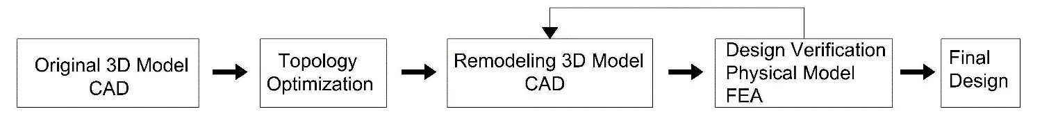
The structurally optimal design approach is illustrated in Figure 1 [38]. First, a three-dimensional CAD modeling program was used to develop the original CAD design. Next, a structural analysis was performed on the original design under specified loading conditions to determine the distributions of strain and stress. In accordance with the stress and strain distributions, topology optimization removes material from locations that do not substantially contribute to supporting the applied loads. The component was redrawn using CAD software (Autodesk Fusion 360) based on the outcomes of topology optimization. Subsequently, FEA was used to confirm that the revised CAD model could withstand the loads and comply with the design guidelines. Physical model verification was performed using any of the bodily prototyping methodologies if the model met the validation criteria. To perform this analysis, three-dimensional finite elements were used. Initially, codes were written in MATLAB for three-dimensional finite elements with three degrees of freedom at each node, including axial deformation. The Fusion program was then used for topological optimization [31,32].
2.4. Method of Structural Optimization of Constructions
The method chosen for the structural optimization of the present constructions is the Solid Isotropic Material with Penalization method (SIMP), which is discussed in detail in the next chapter. This method has many advantages over other structural optimization methods, the most important of which are as follows [23]:
-
Simple and easy to use
-
Compatibility with Finite Element Analysis (FEA)
-
Effective Computational Results
-
Infinite Design Space
-
The ability to interpret physical
-
Penalization Promotes Realistic (0–1) Designs
-
Flexibility
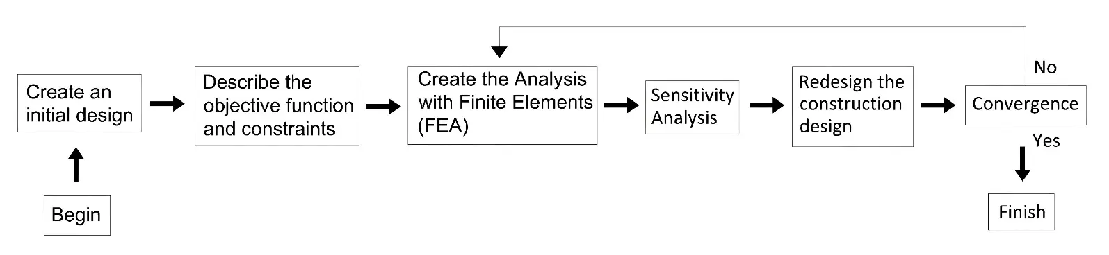
Thus, the block diagram of the SIMP method is presented below, which analyzes the process followed to complete a structural optimization of a construction through this specific method [23], as shown in Figure 2.
2.5. Mathematical Formulation of Structural Optimization Problem-Solving
The principles of optimization theory state that design parameters, restrictions, and objective functions are the three key elements of optimization design. A set of factors that can be adjusted to improve the performance is referred to as the design variable. Constrained circumstances restrict the design and are necessary for the design variables and other performances. This is because the goal function depends on the design variables and demands optimal design performance [38]. The Solid Isotropic Material with Penalization (SIMP) algorithm is one of the most widely used techniques in continuous optimization design. It considers the element material density, whose density fluctuates continuously from 0 to 1, as the design variable [38]. When an element’s density is zero, it is empty; when it is one, it is real; and when its density value is between 0 and 1, it represents fictitious items [38]. This leads to the following expression for the mathematical optimization model:
|
|
(1) |
In this formula, x = (x1, x2, ... xn), and the design variable denotes the cell’s density. In addition, the design objective f(x) represents the mechanical characteristics or weight, and the design responses that need to be constrained are represented as g(x) and hk(x).
Several elements of traditional structural optimization issues are combined into an optimal material layout problem. The goal of topology optimization is to determine the ideal distribution of the elements within a predefined design domain Ω. Body forces F are applied together with traction forces T at boundary Γ𝑡, and the body is restricted at these limits with 1Γ𝑢 and 2Γ𝑢. Within domain Ω, certain places require material to exist, while other sections must be empty. The only factors known are the boundary conditions, applied loads, and material qualities. A few further limitations include whether or not the material is present in certain sections of the domain. Within domain Ω, Ω𝑚𝑎𝑡 represents the optimally dispersed material and represents a fraction 𝜙 of the total volume or area. The material’s size, shape, and connection are the unknowns in this problem. The resulting material distribution Ω𝑚𝑎𝑡 inside the domain Ω𝑚𝑎𝑡 is depicted below (Figure 3).
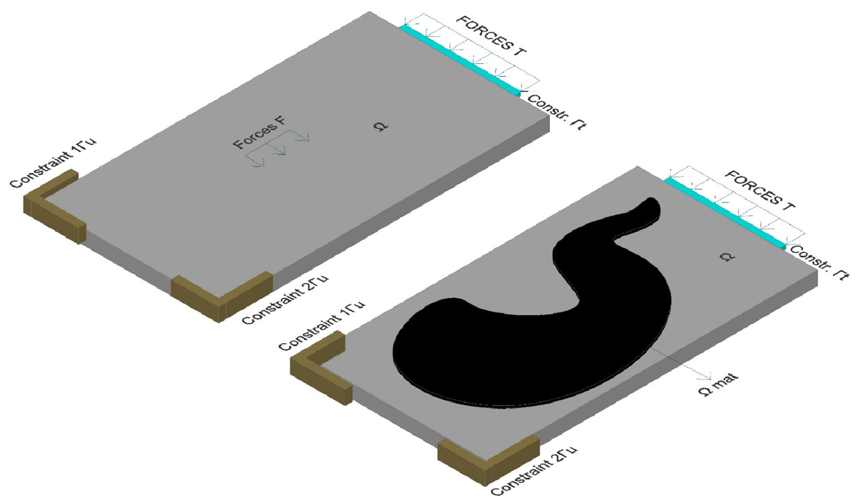
Figure 3. General cross-section with forces and constraints (up) and final topology optimization Ωmat, inside Ω (down).
The optimization problem about topology is a “0-1” integer optimization problem. Initially, 𝑁 finite components are created by discretizing the design domain Ω. Every finite element is a density x design variable. In other words, material may or may not be present in any finite element. If density is equivalent to one, there is stuff there, and the cell has a black paint job. When the density is 0, the cell is painted white since there is no substance. A vector x ∈ ℝ𝑁 can be created by combining the design variables. The design variables determine the structure K(x) ∈ ℝd × d, that is, the global stiffness matrix, where 𝑑 is the total number of levels of flexibility. The following governing equilibrium equations can be used to derive the displacement vector U ∈ ℝ:
|
```latex\mathbf{K}\left(\mathbf{x}\right)\cdot \mathbf{U}=\mathbf{F}``` |
(2) |
where the total of all applied body, surface, and point forces is represented by the external load vector, F ∈ ℝ𝑑, and U and K(x) symbolize the kinematic degrees of freedom and the matrix of the global stiffness, respectively.
Under the assumption of linear elasticity, the constitutive and kinetic equations can be used to connect the strain and stress tensors to the displacement vector:
|
(3) |
|
|
(4) |
The constitutive matrix E is contingent upon the Poisson’s ratio 𝜈 and Young’s modulus E0 of that particular material. To approximately describe the bounds of the continuum structure, the discretized domain produces a black-and-white solution when the density design variable is one of the limiting values, either zero or one. By replacing the density’s integer variables with continuous variables driven by a penalty value 𝑝 ≥ 3, the “0-1” problem may be achieved, and the design variables will approach the ideal discrete values of 0 and 1. This method is known as SIMP (Solid Isotropic Material Penalization) [17].
For any element 𝑒, the material characteristics E𝑒 may be written as follows:
|
(5) |
where the coefficient of penalization power is denoted by 𝑝, and E represents the solid material’s Young’s modulus. It is important to note that a lower bound on the xe needs to be established for computational reasons. Considering that the volume element values are set to:
|
(6) |
where the default value of xmin is 10−3.
The stiffness of every element K𝑒 may be adjusted using SIMP as follows:
|
(7) |
where K0 is the element flexibility when 𝑥𝑒 = 1, and p is the penalty factor, which is often set to p > 3. The global flexibility matrix K can be expressed as follows:
|
(8) |
The Ω𝑚𝑎𝑡 volume has to be expressed as a percentage $$\varphi$$ of the total Ω volume.
|
(9) |
where ve is the element’s volume e.
The total flexibility is the objective function of the problem, which is represented by the compliance of the structure as follows:
|
```latexc={\mathbf{F}}^{\mathrm{T}}\cdot \mathbf{u}``` |
(10) |
The mathematical formulation of the topology optimization problem for structures can be expressed as follows (Figure 4):
|
(11) |
 |
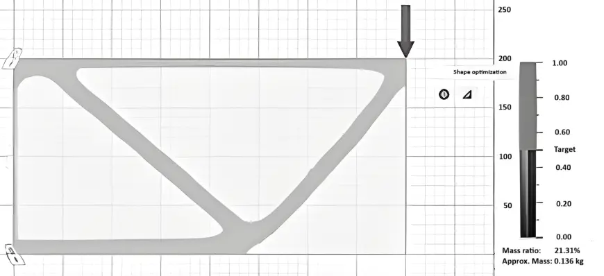 |
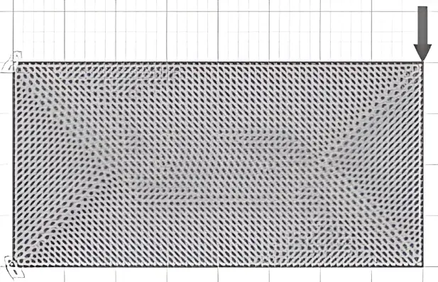
Figure 4. The initial vector is divided into N finite elements (left) and final topology optimization (right).
The total flexibility is the objective function of the problem, which is represented by the compliance of the structure as follows:
In the right figure, white components show that there is no material present xe = 0. The substance xe = 1 is present in black cells. The density for gray components is 0 < xe < 1.
2.6. General Analysis Data
As a numerical example illustrating the above approach, the two types of steel purlins to be analyzed are presented below. Specifically, a rectangular purlin measuring 160 mm in height and 80 mm in width, as well as an IPE 160 purlin, were selected for analysis. The stresses and displacements of the above two cross-sections will be found, and the optimization of the above cross-sections will be studied through a finite element program. After deciding the way and cross-section of optimization for the initial purlin cross-sections, the stresses and displacements of the optimized cross-sections will be found again, in order to draw specific conclusions from them. These two types of purlins were chosen for the following reasons.
2.7. Material Properties
Structural steel was selected as the construction material for all analyses in this study, the properties of which are listed in Table 1.
Table 1. Material properties.
|
Density |
7850.00 kg/m3 |
|
Young’s Modulus |
210,000.00 MPa |
|
Poisson’s Ratio |
0.30 |
|
Yield Strength |
235.00 MPa |
|
Ultimate Tensile Strength |
345.00 MPa |
|
Kind of structural steel |
S235 (in accordance with EN 10025European standard) |
|
Thermal Conductivity |
56.00 W/(m·°C) |
|
Thermal Expansion Coefficient |
1.200 × 10⁻⁵/°C |
|
Specific Heat |
480.00 J/(kg·°C) |
|
Purlins’ length |
5.00 m |
|
Purlins’ distributed load |
3.68 kN/m |
|
Purlins’ Border conditions |
Anchorages at both ends (fixed-ended beam) |
2.8. Loads and Constraints
A distributed load of 3.68 kN/m was used for all analyses in this study. It is worth mentioning that the loads of the under-optimization purlins were calculated in detail using Eurocode 3 (wind, snow, permanent, and mobile loads) based on the geometry of the construction and the available roof panel of the studied metal frame. For the boundary conditions, a fixed beam was used at both ends of the studied cross-section (fixed-ended beams). It should be noted that in the Figures with the FEA below, the force presented is the resultant force of the distributed load. This is owing to the visualization capabilities of the FEA platform used.
2.9. Analysis of Sensitivity and Optimality Criteria
The goal function for a structure that must support the imposed loads is to minimize global flexibility. The equation $$c={\mathbf{F}}^{\mathrm{T}}\cdot \mathbf{u}$$ can be broken down as follows:
|
(12) |
And as follows, the global flexibility is presented:
|
(13) |
It is necessary to use the Lagrange multiplier approach to address this problem. Next, the design variables were updated using a heuristic approach, and the Lagrange multipliers were determined iteratively. The Lagrange function is defined as:
|
(14) |
3. Results
This section presents all the results of the structural optimization analyses completed within the scope of this study. More specifically, two analyses of metal purlins were conducted. A rectangular section analysis and an IPE section analysis. The results and detailed information from these two large analyses are analyzed in depth in this chapter.
These results delve into both the more efficient mechanical behavior and cost reduction of structures through structural optimization, as well as environmental protection through the large removal of material from the interior of the cross-sections [26].
3.1. Loads and Constraints
The current study focuses on the topological optimization of steel purlins in a metal structure using finite elements, which were verified for correctness through finite element and cross-section optimization programs. More specifically, the studied metal structure had a width of 30 m, a length of 60 m, and a height of 5 m. Metal construction consists of a metal roof panel, steel purlins that support the roof panel, metal main beams that support the purlins, and steel columns that support the main beams. In addition, the metal structure has steel stringers that take over all the lateral loads of the structure.
The main objective of this study is the topological optimization of all purlins of the studied construction, as it is a construction that will be erected at public expense and must be as economical as possible, while ensuring all rates of strength and functionality.
Based on the theory of steel structures, the economic distance between the mainframes of a metal structure ranges from 5 to 6 m. In this study, the distance between the main frames was chosen as 5 m. Therefore, given that the distance between the main frames is 5 m and that the Purlins step on the mainframes on their transverse side, the length of the Purlins is obtained at 5 m.
Calculation of the number of purlins in the metal structure studied:
As mentioned above, the purlins press on the frames where the coating will be pressed and transfer the external vertical loads to the carrier.
The economic distance between purlins is 1.5 m, based on the theory of steel structures.
|
```latex\text{Openings}=\frac{\text{Construction width}}{\text{Purlin distance}}=\frac{30.00\text{ m}}{1.5\text{ m}}=20\text{ Openings}``` |
The number of purlins is always “openings + 1”, so the structure needs 21 purlins, 5 m long on one side of the total structure (5 m long). The total length of the structure is 60 m, and 21 purlins of 5 m in length have been calculated in the first 5 m of the length of the total structure; therefore, in order to calculate the total number of purlins of the entire structure, it is sufficient to multiply the number of purlins on one side of the structure by the number 12, to arrive at 60 m in length of the planned construction. Therefore:
|
```latex\text{Total number of purlins 5 m long}=\text{21 purlins}\cdot \text{12}=252\text{ purlins}``` |
As mentioned above, the purlins press on the frames where the coating will be pressed and transfer the external vertical loads to the carrier. The economic distance between purlins is 1.5 m, based on the theory of steel structures. Because of the absolute symmetry of the studied metal structure, by optimizing a purlin of 5 m in length with the given loads that have been calculated in detail through Eurocode 3 (EC3), we determined that all 252 purlins of length 5 m were optimized for the total metal construction. The total load on the steel purlins is a distributed load of 3.68 kN/m, resulting from the transfer of moment and live loads of the metal roof panel to the studied purlin. Their boundary conditions are anchorages at both ends, thus being fixed-ended beams.
3.2. Results of Fixed-Ended Rectangular Cross Section 160 mm in Height and 80 mm in Width
Initially, the stresses and displacements of the original fixed-ended rectangular cross section, 160 mm in height and 80 mm in width, were analyzed, and their results are presented in Figure 5 and Figure 6, respectively. Τo perform the topological optimization, spatially finite three-dimensional arrays have been used. Initially, the nodal displacements were calculated, and then the stresses of the elements. Where the stresses were high, material was removed, and the construction became lighter. The von Mises stress is a scalar invariant derived from the stress state of the material. It represents an equivalent uniaxial stress measure used to assess yielding, is always positive, and remains unchanged regardless of the orientation of the coordinate system because it is calculated directly from the principal stresses.
The stress is calculated for each finite element (in MPa) with red-orange being the highest values and blue being the lowest form 0.006 MPa to 5.125 MPa.
The second figure refers to the displacement in mm form 0.00 to 0.21 mm. In the finite element method, the displacements are first calculated, and then the stresses. For each analysis, we calculate both displacements and von Mises stress. The stress is given in MPa and the displacement in mm. The stresses and displacements of the original fixed-ended rectangular cross-section, 160 mm height and 80 mm width, are presented in the following graphs (Figure 5 and Figure 6).
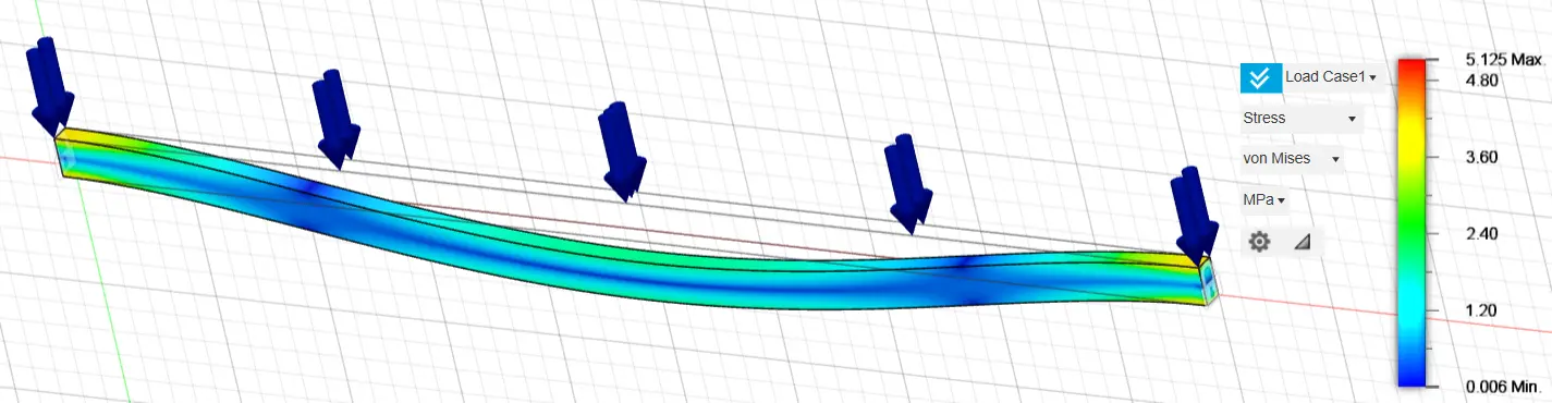
Figure 5. Stress of the original fixed-ended rectangular cross-section 160 mm height and 80 mm width.
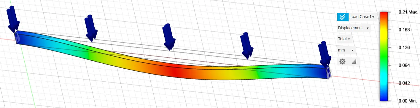
Figure 6. Displacement of the original fixed-ended rectangular cross-section, 160 mm height and 80 mm width.
Thereafter, an initial optimization of the original study structure was carried out by removing 20%, 50% and 70% of the available material, presenting the areas of the structure where stresses are not concentrated and where material removal can be carried out. For the 80% case, the calculated weight of the beam was 413.43 kg, reduced to 254.911 kg for the 50% case and to 138.659 kg for the 30% case (~73% weight reduction). Initial optimization for 80%, 50% and 30% of the construction material of the original fixed-ended rectangular cross-section is presented in the following graphs (Figure 7, Figure 8 and Figure 9).
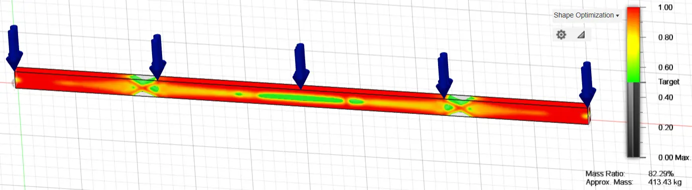
Figure 7. Optimization of the original fixed-ended rectangular cross-section, 160 mm height and 80 mm width, using 80% of the construction material.
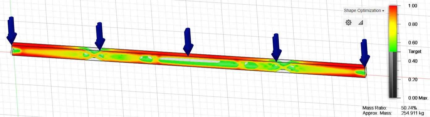
Figure 8. Optimization of the original fixed-ended rectangular cross-section, 160 mm height and 80 mm width, using 50% of the construction material.
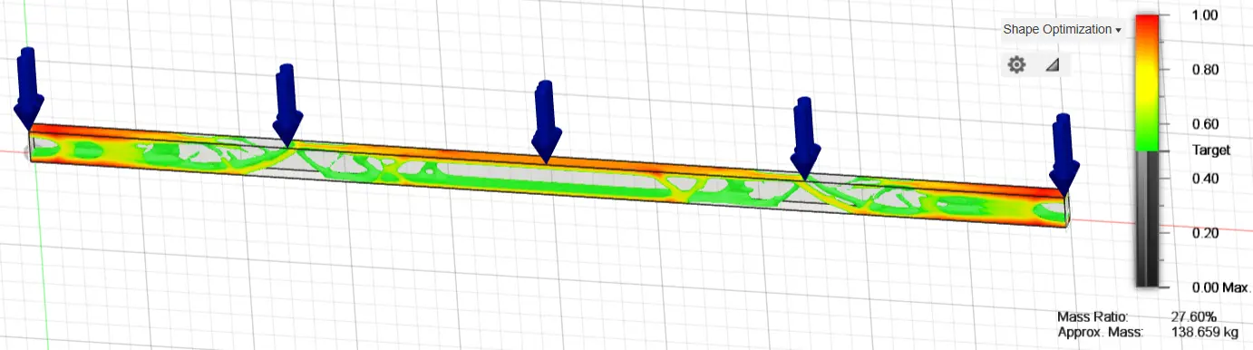
Figure 9. Optimization of the original fixed-ended rectangular cross-section, 160 mm height and 80 mm width, using 20% of the construction material.
The stresses and displacements of the fixed-ended rectangular cross-section, 160 mm in height and 80 mm in width, after the optimization process are presented further below. Three different optimizations of the original fixed-ended rectangular cross-section 160 mm in height and 80 mm in width were analyzed, exploiting 90%, 80%, and 70% of the construction material, respectively, by creating holes in the inner part of the structure in the positions where the optimization graphs show that material removal can be carried out and that they do not show large percentages of stresses.
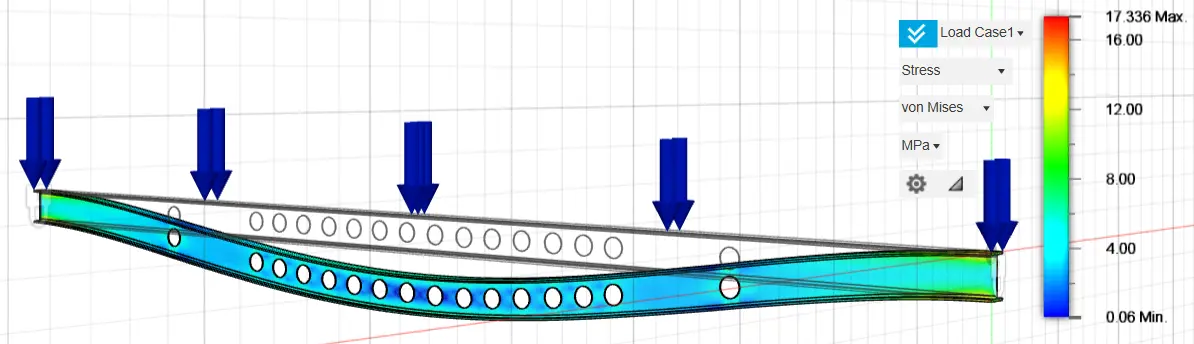
Specifically, nine holes with a diameter of 100 mm were selected for the optimization analysis with the exploitation of 90% of the construction material, 14 holes with a diameter of 120 mm in the optimization analysis with the exploitation of 80% of the construction material and twenty-two holes with a diameter of 120 mm in the optimization analysis with the exploitation of 70% of the construction material. The selection of the above optimization method and the geometric characteristics of the optimization holes were carried out after multiple and repeated analyses, until we managed to have the appropriate material reduction, achieving similar stress and strain rates between the original and optimized structure. The results of the above analyses are presented in the following graphs (Figure 10, Figure 11, Figure 12, Figure 13, Figure 14 and Figure 15).
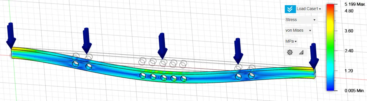
Figure 10. Stress of a fixed-ended rectangular cross-section 160 mm height and 80 mm width, using 90% of the construction material.
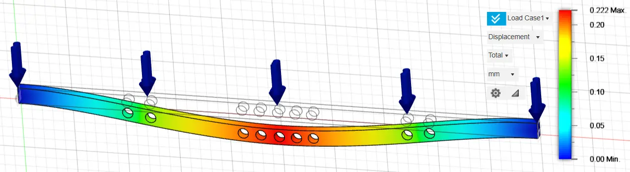
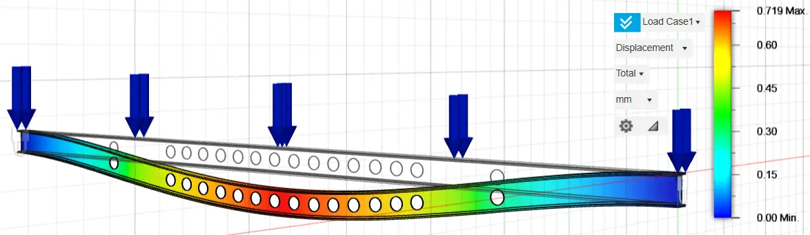
Figure 11. Displacement of a fixed-ended rectangular cross-section 160 mm height and 80 mm width, using 90% of the construction material.
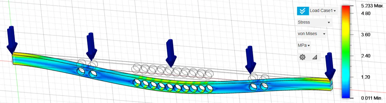
Figure 12. Stress of a fixed-ended rectangular cross-section, 160 mm height and 80 mm width, using 80% of the construction material.
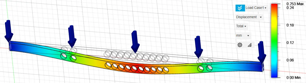
Figure 13. Displacement of a fixed-ended rectangular cross-section 160 mm height and 80 mm width, using 80% of the construction material.

Figure 14. Stress of a fixed-ended rectangular cross-section, 160 mm height and 80 mm width, using 70% of the construction material.
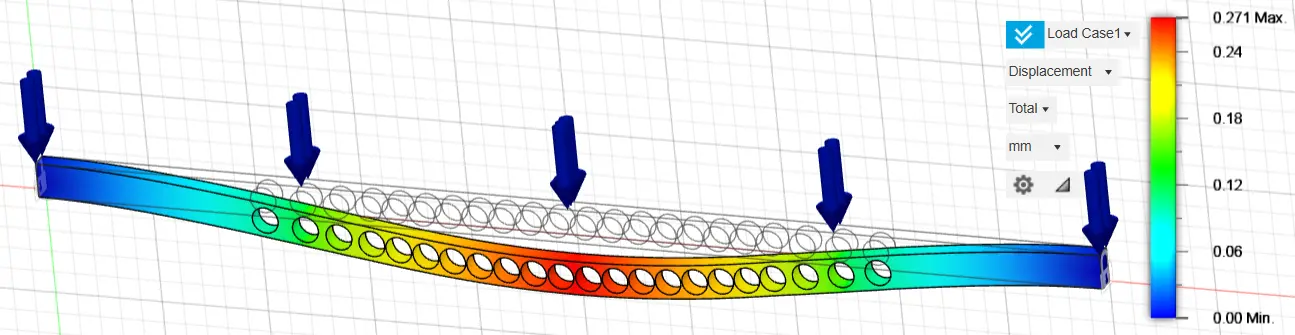
Figure 15. Displacement of a fixed-ended rectangular cross-section 160 mm height and 80 mm width, using 70% of the construction material.
In Table 2 below, the results of stress and displacement analyses for both the original fixed-ended rectangular cross-section of 160 mm height and 80 mm width and the optimized cross-sections of the original cross-section are shown.
Table 2. Results of analyses of a fixed-ended rectangular cross-section, 160 mm height, and 80 mm width.
|
Cross-Sections |
Stress (MPa) |
Displacement (mm) |
Mass (kg) |
No. of Nodes |
No. of Elements |
|---|---|---|---|---|---|
|
Rectangular cross-section 160 mm × 80 mm |
5.13 |
0.21 |
502.40 |
213,597 |
1,135,885 |
|
Optimization using 90% of the construction material |
5.20 |
0.22 |
458.08 |
197,060 |
1,030,760 |
|
Optimization using 80% of the construction material |
5.23 |
0.25 |
412.87 |
176,983 |
909,386 |
|
Optimization using 70% of the construction material |
5.50 |
0.27 |
361.72 |
157,151 |
786,753 |
Based on the above results, it is observed that the optimized cross-sections present similar stress and displacement results in relation to the original design structure, thus certifying the successful optimization of the fixed-ended rectangular cross-section steel purlins in the present study.
3.3. Results of Fixed-Ended IPE 160
The IPE 160 cross-sectional dimensions and properties are presented in Table 3.
Table 3. IPE 160 cross-sectional dimensions and properties.
|
Cross-Section |
Dimensions |
Area |
Weight |
|||
|---|---|---|---|---|---|---|
|
IPE 160 |
h (mm) |
b (mm) |
s (mm) |
t (mm) |
F (mm2) |
G (kg/m) |
|
160 |
82 |
5.0 |
7.4 |
1640 |
1290 |
|
The same process was carried out in relation to the optimization of the rectangular cross-section regarding the optimization of the IPE 160 steel purlin. More specifically, the stresses and displacements of the original purlin IPE 160 were analyzed (Figure 16 and Figure 17) and after this, an initial optimization of the original study structure was carried out by removing 20%, 50% and 70% of the available material, presenting the areas of the structure where stresses are not concentrated and where material removal can be carried out (Figure 18, Figure 19 and Figure 20). The optimization of the original fixed-ended purlin IPE 160 resulted in a beam with 68.491 kg weight for the 80% mass, 42.747 kg for the 50% mass, and 16.642 kg for the 30% mass (~79% reduction).
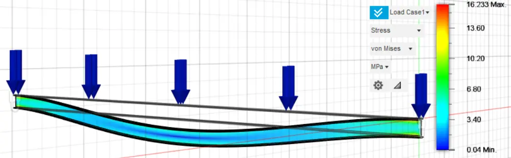
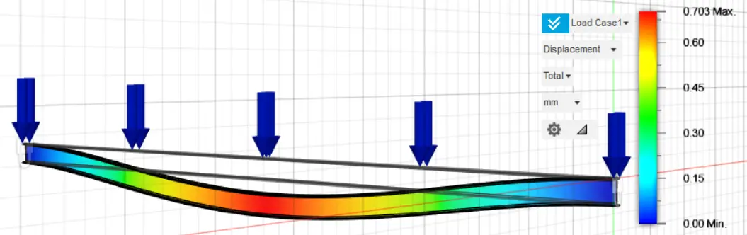
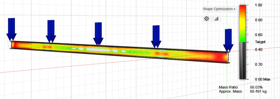
Figure 18. Optimization of the original fixed-ended purlin IPE 160, using 80% of the construction material.
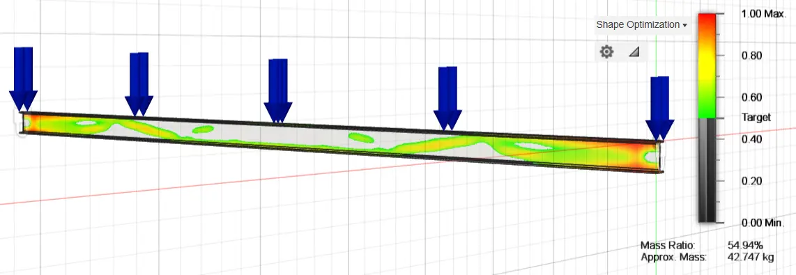
Figure 19. Optimization of the original fixed-ended purlin IPE 160, using 50% of the construction material.
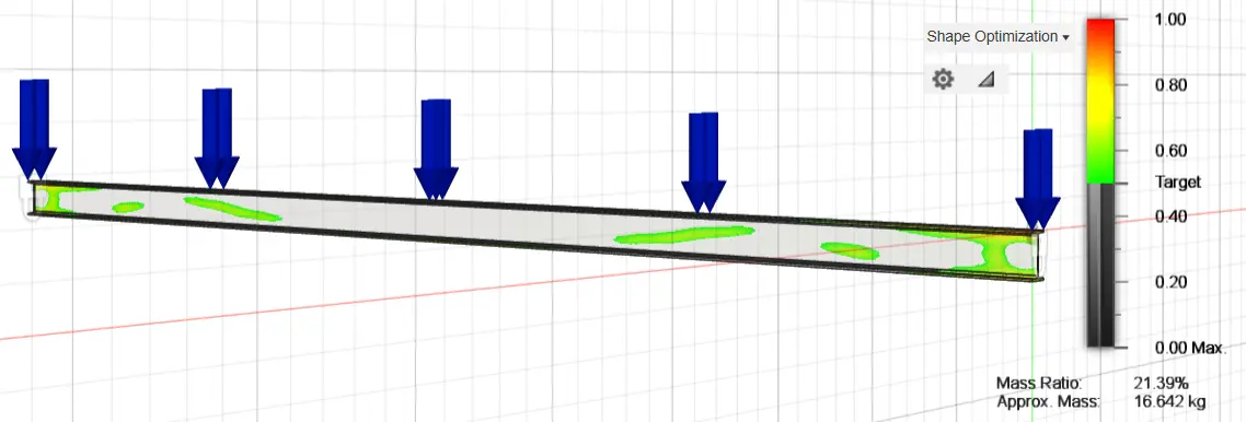
Figure 20. Optimization of the original fixed-ended purlin IPE 160, using 30% of the construction material.
The stresses and displacements of the fixed-ended purlin IPE 160, after the optimization process, are presented below. Four different optimizations of the original fixed-ended purlin IPE 160 were analyzed, exploiting 97%, 94%, 93%, and 90% of the construction material, respectively, by creating holes in the inner part of the structure in the positions where the optimization graphs show that material removal can be carried out and that they do not show large percentages of stresses.
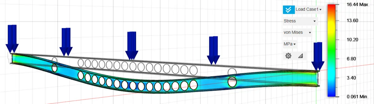
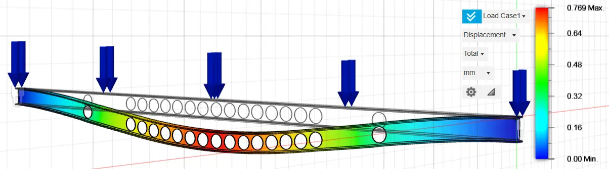
Specifically, 16 holes with a diameter of 80 mm were selected for the optimization analysis with the exploitation of 97% of the construction material, 17 holes with a diameter of 110 mm in the optimization analysis with the exploitation of 94% of the construction material, 16 holes with a diameter of 120 mm in the optimization analysis with the exploitation of 93% of the construction material and twenty-one holes with a diameter of 120 mm in the optimization analysis with the exploitation of 90% of the construction material. The selection of the above optimization method and the geometric characteristics of the optimization holes were carried out after multiple and repeated analyses, until we achieved the appropriate material reduction, resulting in similar stress and strain rates between the original and optimized structures. The results of the above analyses are presented in the following graphs (Figure 21, Figure 22, Figure 23, Figure 24, Figure 25, Figure 26, Figure 27 and Figure 28).
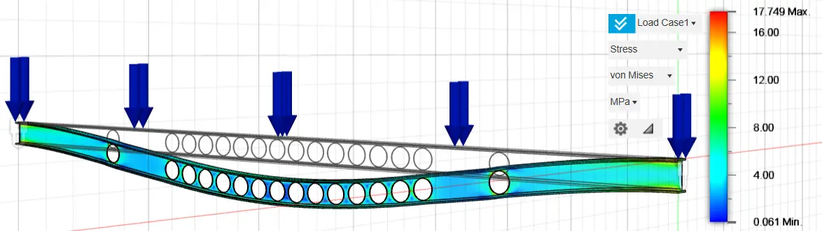
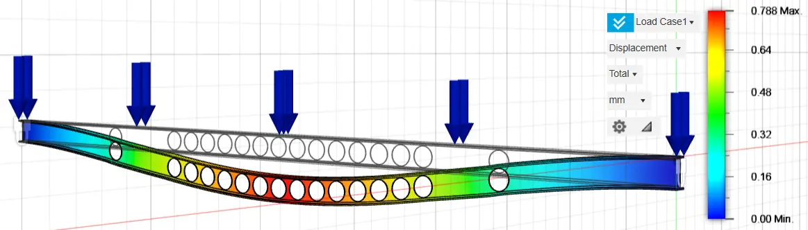
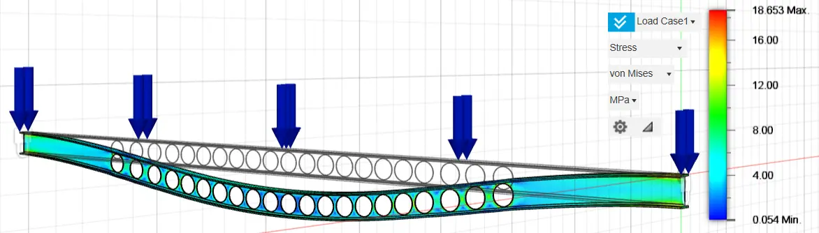
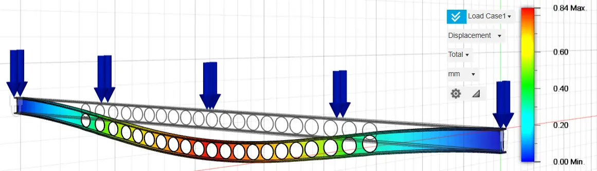
In Table 4 below, the results of the stress and displacement analyses of both the original fixed-ended purlin IPE 160 and the optimized cross-sections of the original cross-section are shown.
Table 4. Results of analysis of a fixed-ended purlin IPE 160.
|
Cross-Sections |
Stress (MPa) |
Displacement (mm) |
Mass (kg) |
No. of Nodes |
No. of Elements |
|---|---|---|---|---|---|
|
IPE 160 |
16.23 |
0.70 |
77.81 |
274,994 |
1,183,668 |
|
Optimization using 97% of the construction material |
17.34 |
0.72 |
75.81 |
247,332 |
1,033,454 |
|
Optimization using 94% of the construction material |
16.44 |
0.77 |
72.99 |
262,777 |
1,132,555 |
|
Optimization using 93% of the construction material |
17.75 |
0.79 |
72.28 |
272,268 |
1,188,419 |
|
Optimization using 90% of the construction material |
18.65 |
0.84 |
70.29 |
260,314 |
1,127,143 |
Based on the above results, as in the rectangular cross-section optimizations that preceded it, it is observed that the optimized cross-sections of IPE 160 present similar stress and displacement results in relation to the original design structure of IPE 160 purlin, thus certifying the successful optimization of the fixed-ended rectangular cross-section steel purlins of the present study.
4. Discussion
In summary, based on the aforementioned analyses and the results of the optimizations of the rectangular cross-section of 160 mm × 80 mm and the cross-section IPE 160, several observations can be drawn, which are analyzed in detail below.
Based on the data presented in Table 2, it can be observed that even though the available construction material decreases, both the stresses and the displacements of the studied steel beam remain almost unchanged. Thus, by applying the optimization of the specific cross-section, the same percentages of stress and displacements are achieved with less construction material; therefore, both savings in available financial resources and greater protection of the environment are achieved, reducing the available construction material as much as possible.
However, based on the load data of the studied purlin, which resulted from the selection of the appropriate ceiling panel, as well as the permanent and mobile loads defined by the regulation (Eurocode 3, EC3), it was observed that the stresses and displacements resulting from both the original solid rectangular cross-section of 160 mm height and 80 mm width, as well as optimized versions of it, were quite small. This gives the design engineer the idea that there is enough material in the studied purlin that could be removed to increase its stress and displacement levels without exceeding the yield limits for stresses and the limits of displacements and bending arrows for distortions.
Thus, in the present study, it was chosen to be studied in exactly the same way as the rectangular cross-section of 160 mm height and 80 mm width, and the IPE 160 cross-section, which has a similar height and width to the studied rectangular cross-section (IPE 160 cross-section height 160 mm and IPE cross-section width 82 mm). However, the IPE cross-section was not solid, as shown in the figures above. After extracting the IPE results, the conclusions of the present study are presented in the conclusion section of this document.
It should be noted that in both analyses, a similar separation was applied on average to finite elements, ensuring that all models in this study had comparable discretization in finite elements (average node discretization 230,000 and average element discretization 1,060,000).
Furthermore, it was observed that the selection of an IPE cross-section is more efficient than the choice of a solid rectangular cross-section, as there is a substantial reduction in mass in the case of the IPE cross-section compared with the rectangular cross-section, which can exceed 90%, despite similar external dimensions (in the case of the rectangular cross-section, there is a single solid cross-section, whereas in the case of the IPE cross-section, there are similar external dimensions to the rectangular cross-section, but with a reduction in the material of manufacture on its web). Thus, an IPE cross-section can provide satisfactory rates of stress and deformation to a structure while significantly reducing its available material, primarily in its web areas.
Concurrently, the differences in stresses and displacements between the rectangular cross-section and the IPE cross-section are considered appropriate and satisfactory in structural applications, as the values of stresses and displacements in the rectangular cross-section are minimal, and the corresponding values of the IPE cross-section are deemed to be within the permissible limits of cross-section adequacy. Consequently, an IPE cross-section provides significantly greater material savings than a solid rectangular cross-section, while maintaining adequacy rates in the limit state and serviceability conditions. In construction works, cross-sections with large percentages of mass are undesirable unless adequacy in the limit states of stress cannot be achieved. If a construction contains cross-sections that contain more material than is necessary to withstand stress, the phenomenon of overconsumption and overuse of available construction materials occurs, which the science of structural optimization aims to address.
Finally, regarding the optimization of the initial cross-sections, it was observed that during the optimization, the analyses of the optimized cross-sections demonstrated similar rates of stress and displacement compared to the original cross-sections. This finding substantiates that the science of structural optimization serves both the community through the conservation of construction materials, which also contributes to environmental protection, and the requirements of design engineers, who aim to achieve the aforementioned savings of construction materials while ensuring the corresponding resistance to the limit states of the stresses they undergo. Civil Engineering constructions are classic constructions that have operated in the same shape for many years. This innovation proposes a new shape for construction. If the thinking underlying classical mechanics were so simple, it would have been built many years ago.
In general, based on this research paper, a new type of structural beam was studied using topological optimization, finite elements, and the SIMP method. On this beam, material was reduced by applying the above method with the main goal of saving costs by reducing the available material, while also reducing the energy it attracts and protecting the environment, if all of the above are achieved. Finally, all of the above is also applied to the architectural appearance of the construction, ensuring a realistic implementation.
With the help of topological optimization, it is possible to build new modern structures with new designs and optimized shapes that have less weight. Changing the beam cross-section is an innovation because it changes large buildings that have been operating with classic cross-sections for many years.
5. Conclusions
The case studies presented clearly demonstrate that structural optimization is an effective design strategy for reducing the weight of the structural components. This reduction offers economic and environmental benefits by conserving significant amounts of material and processing energy, leading to considerable cost savings. In conclusion, this study’s analysis supports the following key points:
In both types of optimizations analyzed (rectangular cross-section optimization and IPE cross-section optimization), the stress and displacement results for the original cross-sections showed minimal variation compared to those of optimized versions. This indicates that cross-section optimization effectively removes a suitable percentage of material from the original design while maintaining stress and strain levels comparable to those found in larger, unoptimized cross-sections.
Reducing the material in cross-sections through structural optimization methods results in constructions that are more cost-effective and environmentally friendly. By lowering the overall mass of the structure, less material is required, which reduces resource exploitation.
In metal structures, standard high-section beams, such as IPE, HEA, and HEB, are more efficient than rectangular cross-sections of the same height and width. The research findings revealed that under similar load conditions, these standard high-rise sections achieved a better stress distribution without surpassing the material yield limits. This allows for significant material savings, contributing to both economic efficiency and environmental sustainability, while maintaining similar structural integrity in terms of stress and deformation.
Topology optimization with additional constraints, including buckling and multiple loading cases, will be studied in the future.
The benefits of topological optimization include reducing the weight of the structure and creating a modern structure. In topological optimization, a basic requirement is the construction of modern structures with modern aesthetics. The basic requirement is the strength of the existing structure and the construction of lighter structures with the same strength. This was achieved in this study.
This study introduces an innovative approach for optimizing civil engineering construction. For several years, traditional structures have adhered to consistent shapes and designs. Proposing a new geometric form or cross-sectional design is a significant advancement, as it departs from the long-standing reliance on conventional configurations.
Although classical mechanics has provided the foundation for these traditional designs, reimagining them has been a challenge. However, advancements in topological optimization now allow for the creation of modern structures with lighter and more efficient designs. This study focuses on redefining beam cross sections, offering a groundbreaking alternative to the standard forms used in large-scale construction for decades. By employing this methodology, this study aimed to achieve more effective material usage and enhanced structural performance, paving the way for a new generation of civil engineering innovations. A future version of this paper will apply structural optimization of a steel purlin not only under bending but also under seismic loads, both on its main axis and on its secondary axis (with superposition of shear stresses, flexural-torsional buckling, etc.).
Author Contributions
T.M., A.M. and M.P.: investigation, software, formal analysis, writing review, and editing; G.E.S.: methodology; N.V.: supervision, validation. All the authors have read and agreed to the published version of the manuscript.
Ethics Statement
Not applicable.
Informed Consent Statement
Not applicable.
Data Availability Statement
The data presented in this study are available upon request from the corresponding authors.
Funding
This research received no external funding.
Declaration of Competing Interest
The authors declare that they have no known competing financial interests or personal relationships that could have appeared to influence the work reported in this paper.
References
-
Srisomporn S, Bureerat S. Geometrical Design of Plate-Fin Heat Sinks Using Hybridization of MOEA and RSM. IEEE Trans. Compon. Packag. Technol. 2008, 31, 351–360. doi:10.1109/TCAPT.2008.916799. [Google Scholar]
-
Zitzler E, Thiele L. Multiobjective Evolutionary Algorithms: A Comparative Case Study and the Strength Pareto Approach. IEEE Trans. Evol. Comput. 1999, 3, 257–271. doi:10.1109/4235.797969. [Google Scholar]
-
Maute K, Frangopol DM. Reliability-Based Design of MEMS Mechanisms by Topology Optimization. Comput. Struct. 2003, 81, 813–824. doi:10.1016/S0045-7949(03)00008-7. [Google Scholar]
-
Beale EML. Introduction to Optimization; Mackley L, Ed.; Wiley: Hoboken, NJ, USA, 1988; ISBN 0471917605/9780471917601. [Google Scholar]
-
Ribeiro TP, Bernardo LFA, Andrade JMA. Topology Optimisation in Structural Steel Design for Additive Manufacturing. Appl. Sci. 2021, 11, 2112. doi:10.3390/app11052112. [Google Scholar]
-
Zhu J, Zhou H, Wang C, Zhou L, Yuan S, Zhang W. A Review of Topology Optimization for Additive Manufacturing: Status and Challenges. Chin. J. Aeronaut. 2021, 34, 91–110. doi:10.1016/j.cja.2020.09.020. [Google Scholar]
-
Ntintakis I, Stavroulakis GE, Sfakianakis G, Fiotodimitrakis N. Utilizing Generative Design for Additive Manufacturing. In Proceedings of the Recent Advances in Manufacturing Processes and Systems; Dave HK, Dixit US, Nedelcu D, Eds.; Springer: Singapore, 2022; pp. 977–989. [Google Scholar]
-
Dorn WS, Gomory RE, Greenberg HJ. Automatic Design of Optimal Structures. J. De Mec. 1964, 3, 25–52. [Google Scholar]
-
Bendsøe MP, Kikuchi N. Generating Optimal Topologies in Structural Design Using a Homogenization Method. Comput. Methods Appl. Mech. Eng. 1988, 71, 197–224. doi:10.1016/0045-7825(88)90086-2. [Google Scholar]
-
Bendsøe MP. Optimal Shape Design as a Material Distribution Problem. Struct. Optim. 1989, 1, 193–202. doi:10.1007/BF01650949. [Google Scholar]
-
Hassani B, Hinton E. A Review of Homogenization and Topology Optimization I—Homogenization Theory for Media with Periodic Structure. Comput. Struct. 1998, 69, 707–717. doi:10.1016/S0045-7949(98)00131-X. [Google Scholar]
-
Campbell SD, Sell D, Jenkins RP, Whiting EB, Fan JA, Werner DH. Review of Numerical Optimization Techniques for Meta-Device Design [Invited]. Opt. Mater. Express 2019, 9, 1842–1863. doi:10.1364/OME.9.001842. [Google Scholar]
-
Akessa AD, Lemu HG, Gebisa AW. Mechanical Property Characterization of Additive Manufactured ABS Material Using Design of Experiment Approach. ASME Int. Mech. Eng. Congr. Expo. 2017, 58493, V014T07A004. doi:10.1115/IMECE2017-70144. [Google Scholar]
-
Gebisa AW, Lemu HG. Investigating Effects of Fused-Deposition Modeling (FDM) Processing Parameters on Flexural Properties of ULTEM 9085 Using Designed Experiment. Materials 2018, 11, 500. doi:10.3390/ma11040500. [Google Scholar]
-
Rozvany GIN, Zhou M, Birker T. Generalized Shape Optimization without Homogenization. Struct. Optim. 1992, 4, 250–252. doi:10.1007/BF01742754. [Google Scholar]
-
Eschenauer HA, Olhoff N. Topology Optimization of Continuum Structures: A Review. Appl. Mech. Rev. 2001, 54, 331–390. doi:10.1115/1.1388075. [Google Scholar]
-
Bendsøe M, Lund E, Olhoff N, Sigmund O. Topology Optimization—Broadening the Areas of Application. Control Cybern. 2005, 34, 7–35. [Google Scholar]
-
Liu S, Li Q, Liu J, Chen W, Zhang Y. A Realization Method for Transforming a Topology Optimization Design into Additive Manufacturing Structures. Engineering 2018, 4, 277–285. doi:10.1016/j.eng.2017.09.002. [Google Scholar]
-
Plevris V, Almutairi A, Rios AJ. Advancing Sustainability Through Structural Optimization: Innovations in Material Efficiency and Environmental Impact Reduction. In Proceedings of the 1st International Conference on Net-Zero Built Environment, Oslo, Norway, 19–21 June 2024; Kioumarsi M, Shafei B, Eds.; Springer: Cham, Switzerland, 2025; pp. 1611–1623. [Google Scholar]
-
Tang T, Wang L, Zhu M, Zhang H, Dong J, Yue W, et al. Topology Optimization: A Review for Structural Designs under Statics Problems. Materials 2024, 17, 5970. doi:10.3390/ma17235970. [Google Scholar]
-
Dzierżanowski G. On the Comparison of Material Interpolation Schemes and Optimal Composite Properties in Plane Shape Optimization. Struct. Multidiscip. Optim. 2012, 46, 693–710. doi:10.1007/s00158-012-0788-2. [Google Scholar]
-
Lógó J, Ismail H. Milestones in the 150-Year History of Topology Optimization: A Review. Comput. Assist. Methods Eng. Sci. 2020, 27, 97–132. [Google Scholar]
-
Aldarrouj SN, Alshannour I. Topology Optimization Generating System. In Topology—Recent Advances and Applications; Bracken P, Ed.; IntechOpen: London, UK, 2023; ISBN 978-1-83769-558-4. [Google Scholar]
-
Wu J, Sigmund O, Groen JP. Topology Optimization of Multi-Scale Structures: A Review. Struct. Multidiscip. Optim. 2021, 63, 1455–1480. doi:10.1007/s00158-021-02881-8. [Google Scholar]
-
Liu S, Li Q, Hu J, Chen W, Zhang Y, Luo Y, et al. A Survey of Topology Optimization Methods Considering Manufacturable Structural Feature Constraints for Additive Manufacturing Structures. Addit. Manuf. Front. 2024, 3, 200143. doi:10.1016/j.amf.2024.200143. [Google Scholar]
-
Muayad H, Raffaele C, Marco D, Hamed F, Movahedi Rad M. Thermo-Mechanical Reliability-Based Topology Optimization for Imperfect Elasto-Plastic Materials. Int. J. Mech. Mater. Des. 2025, 1–22. doi:10.1007/s10999-025-09799-9. [Google Scholar]
-
Habashneh M, Movahedi Rad M. Plastic-Limit Probabilistic Structural Topology Optimization of Steel Beams. Appl. Math. Model. 2024, 128, 347–369. doi:10.1016/j.apm.2024.01.029. [Google Scholar]
-
Xie W, Xia Q, Yu Q, Li Y. An Effective Phase Field Method for Topology Optimization without the Curvature Effects. Comput. Math. Appl. 2023, 146, 200–212. doi:10.1016/j.camwa.2023.06.037. [Google Scholar]
-
Cheng X, Jia M, Wang P, Luo L. A High-Resolution Optimization Method for Large-Scale Structural Design Considering Multiple Sub-Region Volume Constraints. J. Build. Eng. 2025, 106, 112512. doi:10.1016/j.jobe.2025.112512. [Google Scholar]
-
Chamatidis I, Stoumpos M, Kazakis G, Kallioras NA, Triantafyllou S, Plevris V, et al. Overview on Machine Learning Assisted Topology Optimization Methodologies. In Machine Learning in Modeling and Simulation: Methods and Applications; Rabczuk T, Bathe K-J, Eds.; Springer International Publishing: Cham, Switzerland, 2023; pp. 373–394; ISBN 978-3-031-36644-4. [Google Scholar]
-
Sigmund O. A 99 Line Topology Optimization Code Written in Matlab. Struct. Multidiscip. Optim. 2001, 21, 120–127. doi:10.1007/s001580050176. [Google Scholar]
-
Andreassen E, Clausen A, Schevenels M, Lazarov BS, Sigmund O. Efficient Topology Optimization in MATLAB Using 88 Lines of Code. Struct. Multidiscip. Optim. 2011, 43, 1–16. doi:10.1007/s00158-010-0594-7. [Google Scholar]
-
Shin S, Shin D, Kang N. Topology Optimization via Machine Learning and Deep Learning: A Review. J. Comput. Des. Eng. 2023, 10, 1736–1766. doi:10.1093/jcde/qwad072. [Google Scholar]
-
Rozvany G. The SIMP Method in Topology Optimization—Theoretical Background, Advantages and New Applications. In 8th Symposium on Multidisciplinary Analysis and Optimization; Multidisciplinary Analysis Optimization Conferences; American Institute of Aeronautics and Astronautics: Reston, VA, USA, 2000. [Google Scholar]
-
Yarlagadda T, Zhang Z, Jiang L, Bhargava P, Usmani A. Solid Isotropic Material with Thickness Penalization—A 2.5D Method for Structural Topology Optimization. Comput. Struct. 2022, 270, 106857. doi:10.1016/j.compstruc.2022.106857. [Google Scholar]
-
Rosinha IP, Gernaey KV, Woodley JM, Krühne U. Topology Optimization for Biocatalytic Microreactor Configurations. In Computer Aided Chemical Engineering; Gernaey KV, Huusom JK, Gani R, Eds.; Elsevier: Amsterdam, The Netherlands, 2015; Volume 37, pp. 1463–1468; ISBN 1570-7946. [Google Scholar]
-
Kaminakis NT, Stavroulakis GE. Topology Optimization for Compliant Mechanisms, Using Evolutionary-Hybrid Algorithms and Application to the Design of Auxetic Materials. Compos. B Eng. 2012, 43, 2655–2668. doi:10.1016/j.compositesb.2012.03.018. [Google Scholar]
-
Arora JS. Introduction to Optimum Design; Elsevier: Amsterdam, The Netherlands, 2004. [Google Scholar]