New Model of Multicomponent Raw Materials and Its Use in Intensifying Hydrotreating Process of Diesel Fuel

New Model of Multicomponent Raw Materials and Its Use in Intensifying Hydrotreating Process of Diesel Fuel
Received: 21 July 2025 Revised: 12 September 2025 Accepted: 10 October 2025 Published: 23 October 2025

© 2025 The authors. This is an open access article under the Creative Commons Attribution 4.0 International License (https://creativecommons.org/licenses/by/4.0/).
1. Introduction
Hydrotreating of diesel fuel is one of the largest-scale catalytic processes in oil refining. Mathematical modeling of this process is complicated by its implementation in a three-phase system: liquid feedstock, hydrogen-containing gas, and double-functional solid catalysts that provide homolytic and heterolytic hydrogenation reactions of numerous organosulfur compounds, which significantly complicates the formation of mathematical models of the process [1,2,3,4,5]. In industry, hydrotreater process flow sheets are conservative in terms of the hardware of the reactor plant and usually represent a complex of two to four reactors operating in series.
The required loading of the catalyst into the reactors is proportional to the productivity of the installation and increases extensively (several times) with an increase in the purification depth. For Euro 5 vehicles, the sulfur content in diesel fuel is limited to 10 ppm (1 ppm = one part per million = 1 mg/kg), which is achieved by increasing the contact time of the feedstock with the catalyst in the hydrotreating reactors [6]. For this reason, the loading of expensive catalyst into the reactor block of the plant reaches 200–600 m3.
The degree of activity of sulfur compounds in hydrogenolysis reactions varies and decreases in this order: mercaptans > sulfides > thiophens > benzothiophens > dibenzothiophens. At the same time, most difficult-to-hydrogenate compounds of the thiophene series are concentrated primarily in heavy fractions with boiling points above 330 °C [7,8,9,10]. Characteristically, the quality and extent of hydrotreating of diesel fuel and the overall cleaning process are determined by the interaction with hydrogen of a relatively small amount of difficult-to-hydrogenate organic sulfur impurities, while easily hydrogenatable compounds have already undergone hydrogenolysis.
In this situation, the assessment of the composition of the initial diesel fuel by hydrogenable components is of particular importance, which is necessary for mathematical modeling of the process [7,8,11,12,13,14,15,16,17,18,19].
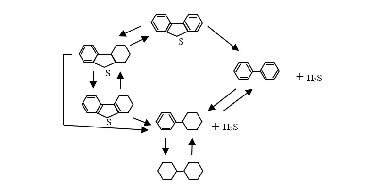
It is almost impossible to take into account the full composition of raw materials for organosulfur impurities when developing a mathematical model for diesel fuel hydrotreatment. Dozens of these components are present in the feedstock in micro-quantities. In addition, hydrodesulfurization reactions are usually carried out through a series of intermediate reactions. For example, during the hydrogenolysis of dibenzothiophene 11 direct and reverse reactions occur (Figure 1).
When developing a mathematical model for hydrotreating, researchers characterize the composition of raw materials using a conditional model. This model reduces the variety of impurities to several pseudocomponents or lumps [16,17,20]. Often, researchers group organosulfur impurities into one or two pseudo-components based on their reactivity in hydrodesulphurization reactions (Figure 2). The number of pseudo-components determines whether a two-, three-, or four-component kinetic model for diesel fuel hydrotreatment is forming. Pseudo-components can be formed based on the reactivity of impurities, which includes groups of organosulphur impurities with very high, high, low, or very low reactivity [20].
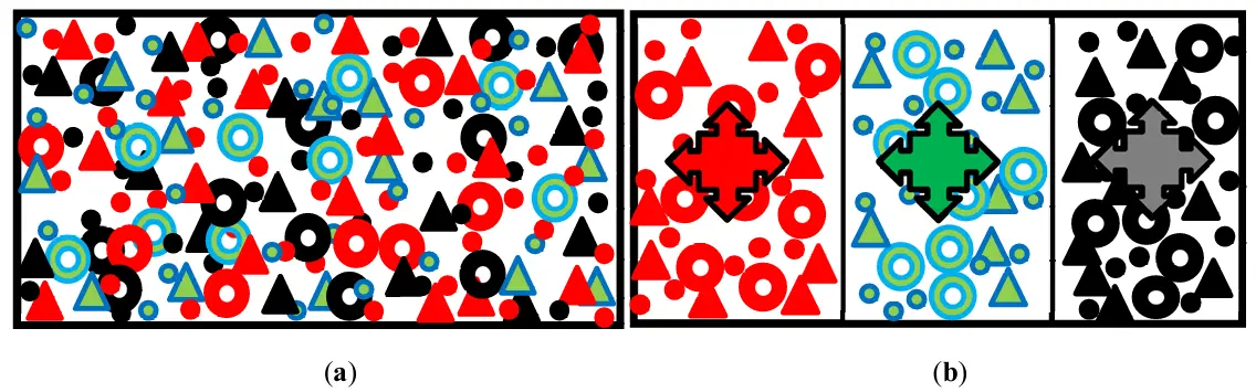
Figure 2. The real distribution of organosulfur impurities of several (for example, three) homologous series in the hydrotreated diesel fuel feedstock (a) and the model of this feedstock as three pseudocomponents, each of which is a combination of all members of the homologous series (b). ●, ▲, and -homologues, e.g., disulfides, with successively increasing boiling points and decreasing reactivity.
There are many unresolved problems with this widely used model. It does not take into account that homologues, or groups of compounds with significantly different boiling points, have different reactivity. Additionally, selecting fractions of different homologous compounds from hydrotreated feedstock for experimental determination of kinetic parameters is a very time-consuming process. In model calculations, the concentration of pseudo-components is determined as their number per cubic meter of feedstock, which leads to an increase in reaction time.
The proposed work considers a fundamentally new model of diesel fuel with hydro-degreased impurities, with a large number of pseudo-components and different principles of their formation, simple analytics, and its features and prospects for use in calculations and improvement of the industrial hydrotreatment process.
2. Methodical Part
Since in this work, we solve the problem of comparing different variants of hydrotreatment reactor blocks to remove organosulfur impurities under identical technological conditions, there is no need for a complex hierarchical model of catalytic hydrotreating. Due to this, the reactor is calculated based on the following assumptions:
-
Quasi-homogeneous reaction flow within the reactor;
-
Constant velocities of local flow jets and ideal displacement hydrodynamic model in the reactor;
-
Isothermicity of the process;
-
Stationarity of the process;
-
Constant catalyst activity over time τ;
-
The content of total organosulphur in the feedstock or its narrow fractions is treated as an organosulfur pseudo-component, and its concentration is determined by analyzing total sulfur;
-
Effective rates of hydrodesulphurization reactions for pseudocomponents.
Under these assumptions, the mathematical model of a hydrotreating reactor, when analyzing the process using N organosulfur pseudocomponents, takes the form of the following system of equations
|
|
(1) |
where CSi and ki are the concentration of the organosulfur component and the effective reaction rate constant of the ith pseudocomponent, respectively.
Numerical values of the concentrations of organosulfur components in the hydrotreating feedstock and effective rate constants of the hydrodesulfurization reactions were taken from independent literature sources.
The mathematical model of the reactor was solved by the Runge-Kutta method, and a calculation program allowed us to determine the change in the concentrations of pseudo-components during the process, as well as the residence time of the reaction mixture in the reactor, at which it will be up to a given degree of purification of the raw material. The catalyst volume in the reactor is then calculated based on the reaction time.
Model (1) with the above assumptions was used when comparing different configurations of industrial reaction units of hydrotreating plants.
3. Results and Discussion
A new model has been proposed to express the composition of multicomponent hydrotreating raw materials. In this model, pseudo-components combine organosulfur impurities of raw materials not by group composition, but by the boiling point of narrow fractions of raw materials (Figure 3). When developing a new model of the composition of raw materials for hydrotreating, together with V. A. Zhilina, we proceeded from the following provisions [21]:
The entire flow of the raw material to be treated consists of N local jets;
A combination of all organosulfur impurities of different classes and homologous series in the local jet forms a pseudocomponent of the local jet;
Concentration of any pseudocomponent in the local jet is determined by analyzing for total sulfur, which greatly simplifies analytical part and experimental work required to support the hydrotreating processes;
Instead of local jets for raw materials flow, narrow fractions of raw materials are considered.

Figure 3. The proposed new model characterizes hydrotreating raw materials by the content of organosulfur impurities: the raw materials (Figure 2a) are divided into several narrow fractions, and each fraction is analyzed for its total sulfur content, for example, three ●, ▲, and -homologues, e.g., disulfides, with successively increasing boiling points and decreasing reactivity.
The use of the principle of dividing the hydrotreatmentng diesel fraction into narrow, sequentially fractions with density enhancement in the new model of raw materials significantly expands the informational field of this model. In accordance with the reactor model (1), when hydrotreating of raw materials with a large number of narrow fractions, it is possible not only more accurate calculation of the hydrodesulfurization proceos compared to the old model with several pseudo-components, but also calculation of processes within each narrow fraction (Figure 4). A universal program for studying and calculating the process of hydrotreating diesel fuel based on a system of equations allows you to solve the following problems:
-
-
Study of the kinetics of hydrotreating of raw materials with pseudocomponents dispersed therein;
-
-
Study of the kinetics of hydrotreating of raw materials in the form of complex local jets (narrow fractions), each of which contains one pseudo-content;
-
-
Study of the kinetics hygrodesulfurization of individual narrow fractions;
-
-
Study of the kinetics hygrodesulfurization of wide fractions composed of sequences of narrow ones;
-
-
Calculation of the reactor for hydrotreating diesel fuel;
-
-
Calculation of the reactor for hydrotreating wide fractions of diesel fuel composed of a sequence of narrow fractions;
-
-
Calculation of a system of two reactors for hydrotreating light and heavy diesel fuel fractions;
-
-
Calculating catalyst loading in each reactor and selecting optimal distribution of light and heavy wide fraction3s diesel fuel in two reactors ensures minimum catalyst loading to the hydrotreating unit.
The latter tasks were studied because in [22], the identity of loading of the catalyst layer during diesel fuel hydrotreating in different configurations of reactor plants was established. Also, the hypothesis was investigated in [23] about the possibility of cleaning diesel fuel to a sulfur content of less than 300 ppm by dividing raw materials into two fractions.
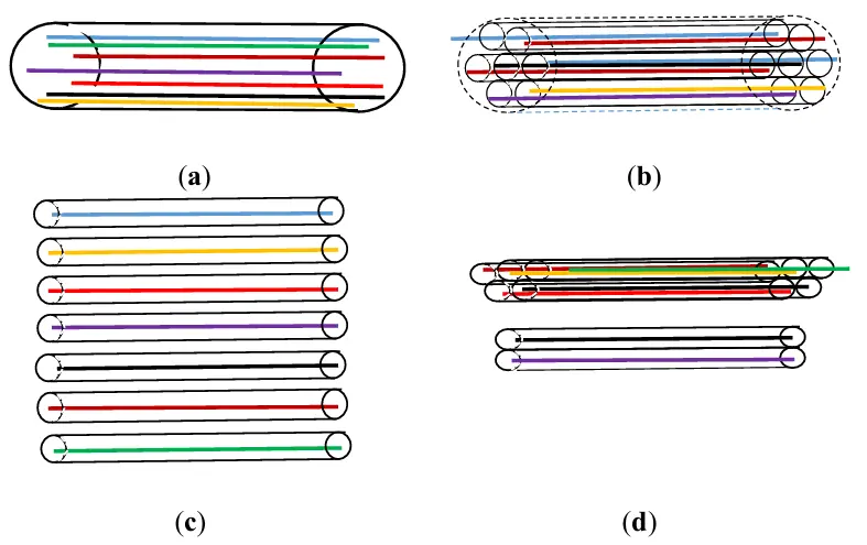
Figure 4. Options for studying the hydrotreating process include using traditional (a) and new (b–d) models to represent the composition of raw materials. All case: all pseudocomponents are distributed in the feed stream (a), all pseudocomponents are located one by one in the local jets of the feed stream (b), hydrotreating separately of each local jet (narrow fraction) of raw materials (c), hydrotreating separately of light and heavy wide fractions of raw materials consisting of a set of local jets (d).
A series of calculations was performed for the feedstock hydrotreating process represented by a model consisting of 20 successive narrow fractions from the beginning of boiling to the end of the process. In each narrow fraction, the combination of organic sulfur compounds was considered as one pseudocompound with an effective constant dehydrosulfurization rate successively decreasing from 20 L/h to one 1 L/h, meaning that light narrow fractions have easily hydrogenated components, while heavy ones have hardly hydrogenated. The concentration of organosulfur impurities in the narrow fractions varied from 8000 to 12,000 ppm, increasing as the narrow fractions became heavier.
Calculation of hydrotreating separately for each local jet (narrow fraction) showed that the duration of light fractions purification is 8–10 times less than for the heaviest 20 fractions to achieve a cleaning depth of 10 ppm (Figure 5).
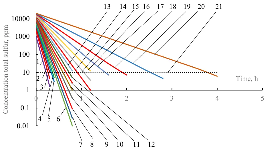
Figure 5. The change of the concentration of pseudocomponents during the separate hydrotreating of 20 narrow fractions. Lines 1–20 are fraction numbers, starting with the lightest; line 21 is the permissible total sulfur content in narrow fractions after hydrotreating (10 ppm).
Calculation of the hydrotreatment of various broad fractions formed by alternating addition of another heavier one to the existing set of light fractions (for example, we add the sixth light fraction to the first five light fractions) made it possible to identify a number of hidden reserves of the diesel fuel hydrotreatment processes (Figure 6).
The hydrotreating characteristics of wide fractions can be conveniently analyzed using the example of a wide fraction consisting of fifteen successive narrow fractions (the curve with design points is shown in Figure 6). While ensuring hydrotreatment of the wide fraction to a level of 10%, the light fractions contained in its composition are subjected to super-deep purification from sulfur. For example, the lowest narrow fraction contains only 0.001 ppm of total sulfur; the fifth narrow fraction contains less than 0.1 ppm; and the eleventh narrow fraction has 8 ppm. The heaviest narrow fractions from the twelfth to the fifteenth fractions contain between 20 and 200 ppm of total sulfur. However, due to the actual mixing of these fifteen narrow fractions, the overall content of sulfur in the purified wide fraction is 10 ppm (red arrow).
Comparison of the materials in Figures 5 and 6 reveals that hydrotreating one 15 narrow fraction to a total sulfur content of 10 ppm takes about 1 h, while a wide fraction composed of 15 first lighter narrow fractions is purified in 20 min.
The advantages of this approach to carrying out a diesel hydrotreating process can be easily demonstrating by the following example.
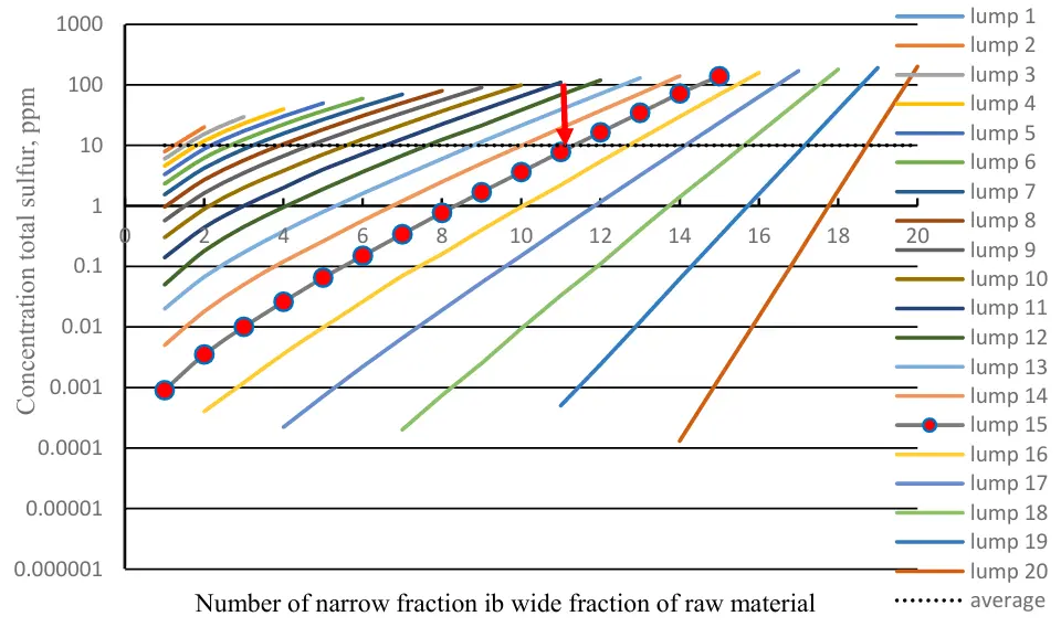
Figure 6. Features of hydrotreatment of wide fractions of raw materials from the number of narrow fractions and pseudocomponents (lumps).
Assume that diesel fuel in the amount G = 100 t/h goes to the hydrotreatment unit for deep desulfurization. Let us consider two options for the treatment of this fuel to remove organosulfur impurities from this fuel. First, this feedstock can be desulfurized in the traditional way in one reactor. Second, the raw materials can be preliminarily divided into two fractions (distillate and residue) if there is a reserve distillation column in the hydrotreating unit. Then these fractions can be hydrogenated and purified from sulfur individually in two reactors. The first light (low boiling) fraction in quantity G = 80 t/h contains sulfur-organic components easily fully hydrogenated within 1 h. Second heavy (high-boiling) fraction of G = 20 t/h containing organosulfur components, which are difficult and slow to react with hydrogen within 3 h.
For deep hydrotreating of diesel fuel, the required loading of the catalyst into the reactors Gkat can be calculated as
|
(2) |
where GF—the feed of raw materials, t/h, and τR—the duration of the reaction, h.
If all the feedstock were in contact with the catalyst for 3 h for complete removal of both easily and slowly hydrated sulfur-organic components, the required loading of catalyst in the reactor Gkat will be equal to 300 tons (as 100 t/h for 3 h) (Figure 7a). If we carry out the hydrogenation of two fractions of feedstock separately in two reactors, then we could achieve the necessary loading of the catalyst in the first reactor 80 tons (as 80 t/h·for 1 h), and in the second reactor 60 tons (as 20 t/h·for 3 h) (Figure 7b). In this case, the overall catalyst loading or both reactors in the reactor unit would be only 140 tons instead of 300 tons in one reactor.
Computer simulation based on a system (1) using a proposed model for raw materials with 16 narrow fractions shows that the loading of the catalysts in two reactors during differential hydrotreatment of diesel fuel is significantly lower than during conventional hydrotreatment with any variant of dividing raw materials into two wide fractions. At the same time, an optimal position exists for the boundary division of raw materials into wide fractions at which the loading of catalyst in both reactors is minimized (Figure 8).
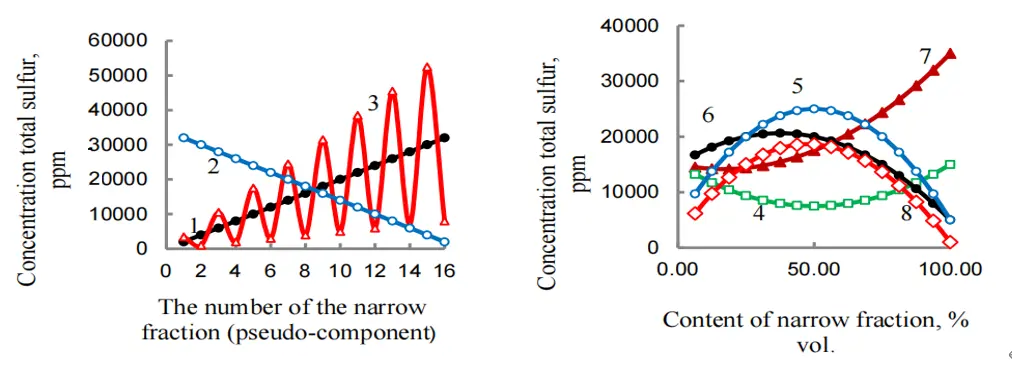
In mathematical modeling of the differential hydrotreating process, diesel fuel pre-fractionates into light and heavy wide fractions. Calculations of hydrodesulphurization were performed for several variants of model fuel as feedstock. In each variant of calculation, the distribution of sulfur-organic components in each wide fraction at the time of chemical process to achieve a concentration of total sulfur at the outlet of the corresponding reactor, being 10 ppm, was determined, as well as the necessary volume of catalyst in each reactor and overall in both reactors. The feedstock (fraction 180–360 °C) was divided into 16, 8 or 4 narrow fractions from which wide fractions formed. Eight variants of different (linear, non-linear, and extreme) distribution functions of sulfur over narrow fractions were considered (Figure 8).
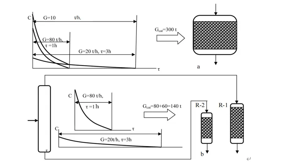
Figure 7. Illustration of the principle of differential hydrogenation of diesel fractions: (a)—usual hydrotreating; (b)—differential hydrotreating.
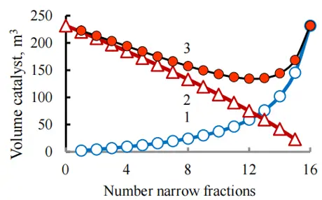
Figure 8. The influence of the number of narrow fractions introduced into the composition of light and wide fractions on the loading of the catalyst into the first reactor (1), the second reactor (2), and in total into both reactors of the hydrotreating unit (3). The raw materials were divided into 16 narrow fractions, taking into account 16 pseudo-components.
Calculations have shown in Table 1 that an increase in the number of narrow fractions leads to an increase in calculation accuracy. When developing differential hydrotreatment, it is impossible to save on preliminary experimental studies. It is necessary to disperse the raw materials in a precise distillation apparatus to obtain a large number of narrow fractions with a temperature difference of 5–7 degrees Celsius, and to obtain initial data for laboratory or pilot plants to calculate reaction rate constants for impurities in these fractions. This will improve the efficiency of the industrial plant by reducing the size of the reactor and catalyst loading.
Table 1. Summary data on the dependence of the total volume of the loaded catalyst in two reactors for different variants of the distribution of total sulfur in the feedstock *.
|
Number of Narrow Fractions (Pseudo-Components) in Raw Materials |
Distribution of Narrow Fractions by Reactor R1 and R2 |
The Total Volume of the Loaded Catalyst in Two Reactors, m3, with Options for the Distribution of Total Sulfur in the Feedstock According to Figure 9. |
|||||||
|---|---|---|---|---|---|---|---|---|---|
|
1 |
2 |
3 |
4 |
5 |
6 |
7 |
8 |
||
|
16 |
1/2...16 |
252.4 |
247.0 |
375.8 |
184.6 |
331.8 |
332.0 |
514.0 |
434.6 |
|
1, 2/3...16 |
239.9 |
239.8 |
358.6 |
181.4 |
318.8 |
319.0 |
488.8 |
414.6 |
|
|
1...3/4...16 |
227.3 |
232.4 |
343.2 |
177.8 |
305.6 |
305.8 |
463.0 |
394.0 |
|
|
1...4/5...16 |
214.7 |
224.6 |
324.4 |
174.2 |
292.2 |
292.2 |
437.2 |
373.0 |
|
|
1...5/6...16 |
202.0 |
216.6 |
310.6 |
170.4 |
278.8 |
278.6 |
411.2 |
351.8 |
|
|
1...6/7...16 |
189.4 |
208.4 |
289.4 |
166.6 |
265.4 |
265.0 |
385.2 |
330.2 |
|
|
1...7/8...16 |
176/9 |
200.2 |
278.6 |
162.8 |
252.2 |
251.4 |
359.6 |
308.8 |
|
|
1...8/9...16 |
164.6 |
192.0 |
254.6 |
159.2 |
239.2 |
238.0 |
334.2 |
287.4 |
|
|
1...9/10...16 |
152.8 |
184.0 |
249.0 |
156.0 |
226.8 |
225.0 |
309.8 |
266.4 |
|
|
1...10/11...16 |
141.5 |
176.4 |
221.4 |
153.6 |
215.2 |
212.8 |
286.6 |
246.6 |
|
|
1...11/12...16 |
131.5 |
170.0 |
226.0 |
152.4 ** |
205.2 |
202.0 |
265.8 |
228.6 |
|
|
1...12/13...16 |
123.5 |
165.0 |
194.6 |
153.2 |
198.0 |
193.8 |
249.4 |
214.0 |
|
|
1...13/14...16 |
119.4 |
163.2 |
224.0 |
157.8 |
195.8 |
190.0 |
240.8 |
206.0 |
|
|
1...14/15, 16 |
123.5 |
168.0 |
192.4 |
16.0 |
203.4 |
196.0 |
249.4 |
212.2 |
|
|
1...15/16 |
149.5 |
188.0 |
316.4 |
192.6 |
234.8 |
225.6 |
302.4 |
256.0 |
|
|
8 |
1/2...8 |
268.9 |
335.6 |
535.6 |
332.2 |
413.0 |
402.4 |
545.8 |
470.2 |
|
1, 2/3...8 |
239.9 |
307.6 |
477.8 |
304.2 |
373.8 |
364.8 |
487.2 |
421.8 |
|
|
1...3/4...8 |
211.1 |
279.0 |
420.4 |
276.2 |
334.8 |
326.6 |
428.2 |
372.4 |
|
|
1...4/5...8 |
182.9 |
250.6 |
364.4 |
249.0 |
296.6 |
289.4 |
370.4 |
323.0 |
|
|
1...5/6...8 |
156.7 |
224.0 |
312.2 |
224.4 |
261.8 |
254.8 |
316.6 |
276.2 |
|
|
1...6/7...8 |
136.5 |
203.8 |
272.0 |
207.4 |
235.8 |
228.4 |
275.2 |
239.4 |
|
|
1...7/8 |
137.1 |
205.8 |
273.0 |
215.0 |
240.0 |
230.6 |
276.0 |
238.4 |
|
|
4 |
1/2...4 |
263.7 |
399.0 |
525.2 |
414.8 |
459.6 |
443.4 |
533.8 |
466.4 |
|
1, 2/3...4 |
199.9 |
314.8 |
398.4 |
325.6 |
356.8 |
344.8 |
404.0 |
355.8 |
|
|
1...3/4 |
148.8 |
247.0 |
375.8 |
184.6 |
331.8 |
332.0 |
514.0 |
434.6 |
|
* Calculations of the hydrotreating process and loading of the catalyst into the reactors were performed by V.A. Zhilina. ** The calculation results closest to the optimal ones are highlighted in different colors.
Calculations of the differential hydrotreat unit with raw material where 16 narrow fractions were combined have shown that the effectiveness of hydrotreatment is largely negatively affected by the overloading of the reactor R1 with heavy narrow fractions and the reactor R2 with light narrow fractions (Figure 10a). There is no doubt about the expediency of combining some of these fractions into the third flow of the medium-wide fraction subjected to hydrotreating in a separate reactor R3. This can be obtained in the rectification column of a hydrotreater plant as a sidestream. The reactor R3 becomes additional equipment of the unit (Figure 10b).
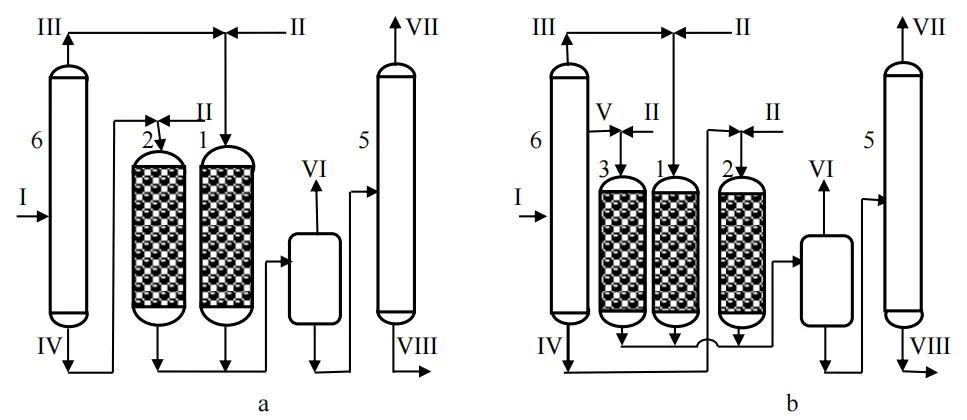
Figure 10. Basic technological schemes of reactor units for differential hydrotreating diesel fuel: two-reactor (a) and three-reactor (b) [24,25]. Apparatuses: 1—reactor R1, 2—reactor R2, 3—reactor R3, 4—separator, 5—stabilizer, 6—distillation column. Streams: I—raw materials, II—hydrogen-containing gas (HCG), III—light fraction of raw materials, IV—heavy fraction of raw materials, V—medium fraction of raw materials, VI—recirculate HCG, VII—hydrocarbon gas, VIII—purified diesel fuel.
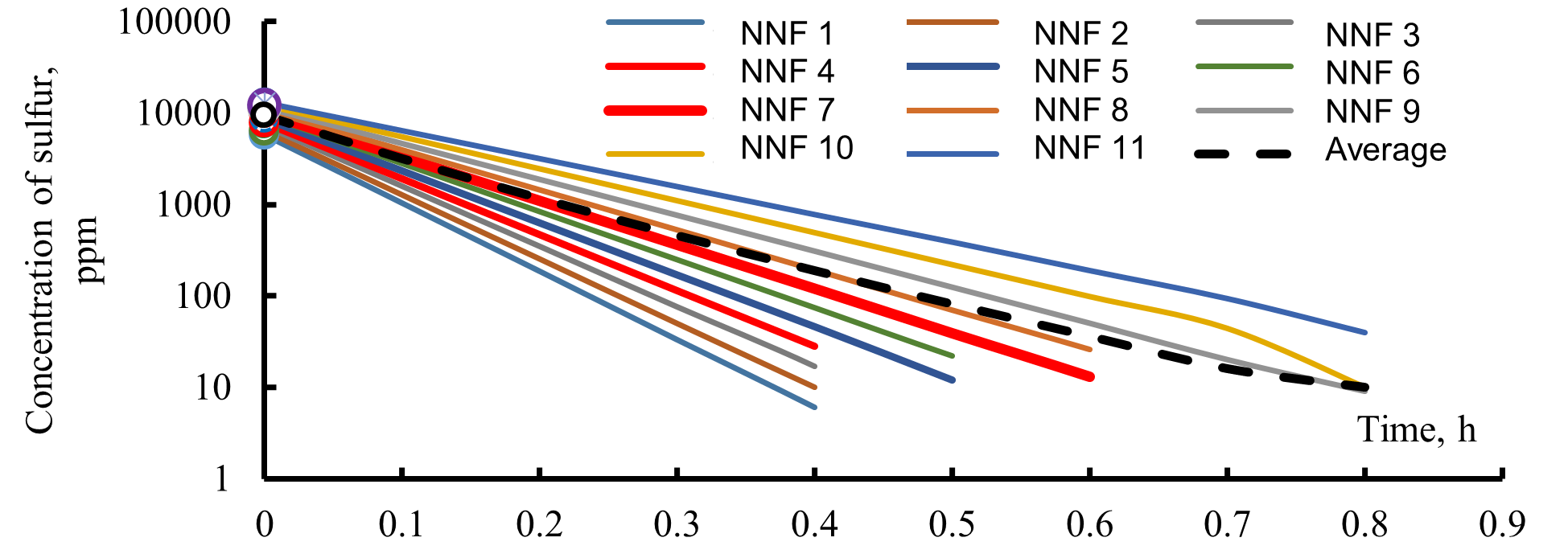
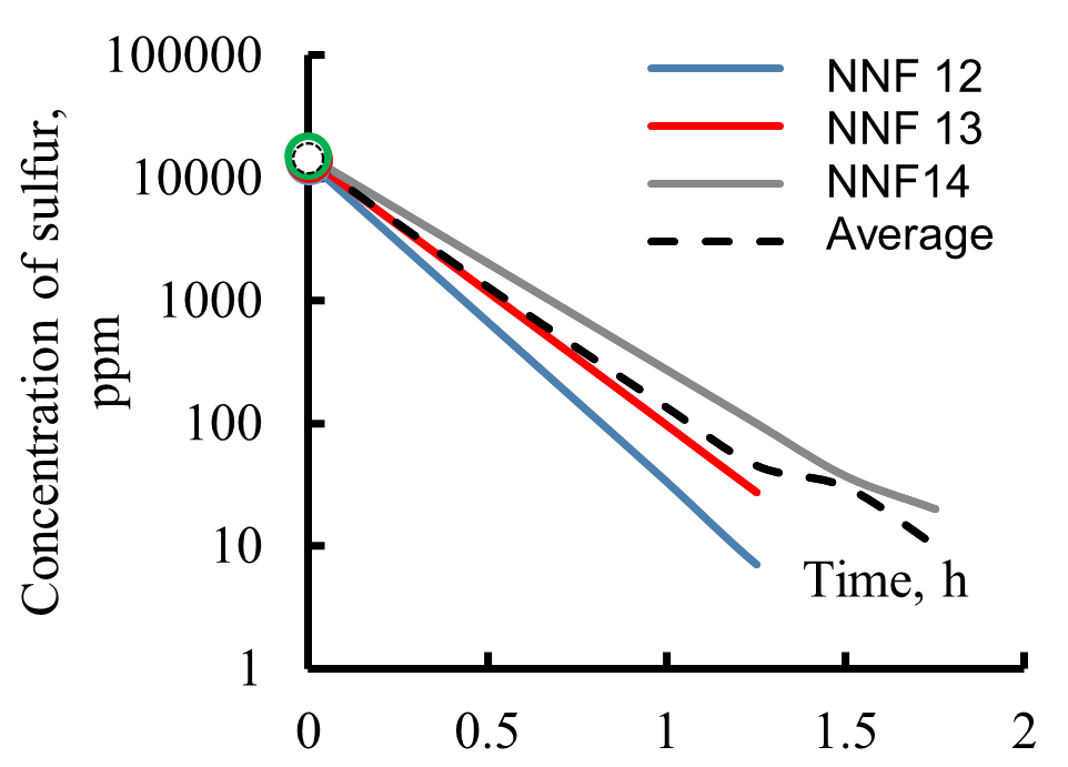
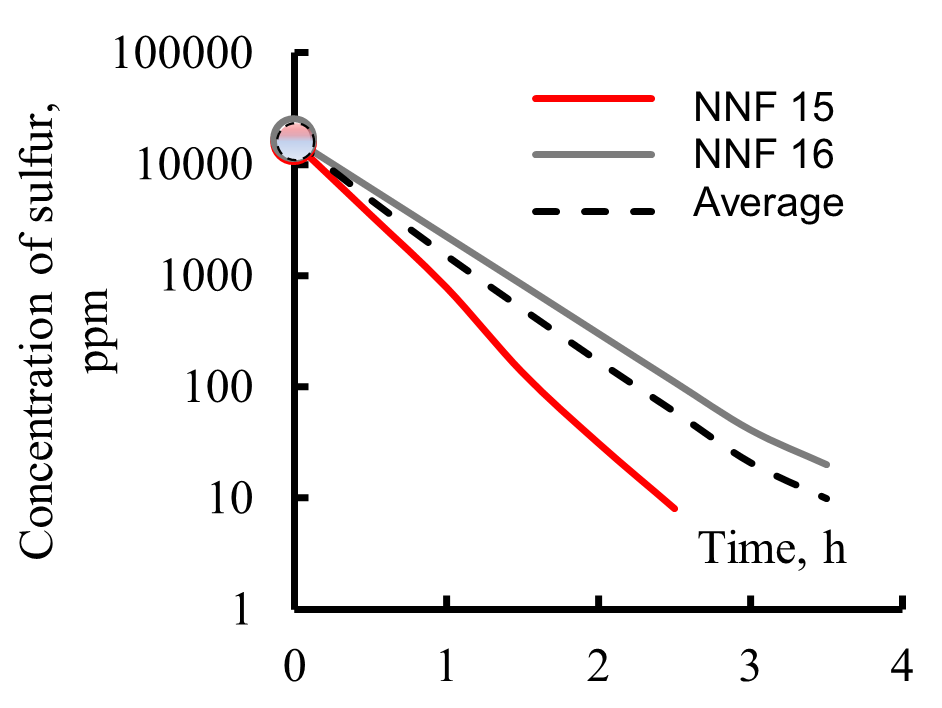
The kinetics of one of the variants of hydrodesulfurization of 16 pseudo-components of the feedstock of the process, divided into three wide fractions, are shown in Figure 11.
Mathematical modeling of a three-reactor scheme for a hydrotreating unit showed that, all other factors being equal, when a set of narrow fractions form a medium wide fraction and are sent to the reactor R-3, then a wide range of narrow fractions appears in the selection of the temperature boundaries for the starting and ending boiling of the medium fraction. It was found that the transition from a two-reactor to a three-reactor hydrotreating system is accompanied by a further reduction in the overall volume of catalyst loaded into the reactor system due to the elimination of the previously discussed factors that negatively affected the operation of the reactors R1 and R2 in the two-reactor system.
 |
|
|
(a) |
|
 |
 |
|
(b) |
(c) |
Figure 11. Kinetics of hydrodesulfurization of pseudo-components contained in narrow fractions forming reactor feedstock: R1 (a), R3 (b), and R2 (c) (NNF—number of narrow fractions, average—sulfur content in a wide fraction).
When selecting the temperature boundaries for the medium wide fraction, the set of narrow fractions provides a monotonically increasing change in the amount of the catalyst loaded into the reactor R3, while the calculated total load volume of the catalyst in all three reactors also has a minimum (Figure 12), similar to that of a two-reactor system. However, a two-reactor unit has a single minimum for catalyst loading, whereas a three-reactor unit has several local minima. To find the global minimum catalyst loading, it is necessary to scan the range of narrow fractions that form the medium wide fraction as a feed for reactor R3. Thus, the minimization of the total catalyst load R in reactors of the hydrotreatment unit for diesel fuel can serve as a criterion of optimality for the designed unit.
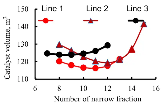
Figure 12. Dependence of the volume of catalyst loaded into the block on the number of narrow fractions, feedstock of the R3: Line 1—narrow fractions 11...14, line 2—narrow fractions 12...15, line 3—narrow fractions 9...12.
The minimum total loading of the catalyst MLC in all reactors of the unit can be used as a criterion to optimize the hydrotreatment of the diesel. The value of R is calculated by equations:
For a two-reactor block:
|
(3) |
For three-reactor block:
|
(4) |
where in Equation (3), Z and Z + 1 are the numbers of the last and first narrow fractions between the light and heavy wide fractions. In Equation (4), X and X + 1, Y and Y + 1 are accordingly the numbers of the last and first narrow fractions between the light and middle and between the middle and heavy wide fractions. In both Equations (3) and (4). N is the total number of narrow fractions in the raw material. GFi, CS0i, CSiend, and ki are accordingly consumption of the narrow ith fraction, concentration of total sulfur before hydrotreating, final concentration of total sulfur, and effective rate constant for any narrow fraction. R1F/C, R2F/C, and R3F/C are the liquid hourly space velocity (LHSV) in the first, second, and third reactors (m3 of raw materials/m3 of catalyst per hour).
As an example, Table 2 shows the results of calculations of reactor units of various configurations of a diesel fuel hydrotreatment unit with a capacity of 800,000 tons/year under the same other conditions with the number of reactors in the unit from 1 to 3. The raw materials took into account 16 narrow fractions and their corresponding pseudo-components.
Table 2. Comparison of characteristics of one-, two-, and three-reactor units of plants for differentiated hydrotreatment of diesel fuel.
Characteristics of the Reactor Unit |
Reactors |
||
|---|---|---|---|
R1 |
R3 |
R2 |
|
One-reactor unit (MLC = 231.7 m3) | |||
|
Distribution of pseudocomponents Feedstock consumption, m3/h Duration of contact of feedstock with catalyst, h Catalyst volume in reactor, m3 |
1–16 100 2.31 231.7 |
||
Optimal two-reactor unit (MLC = 134.2 m3) | |||
|
Temperature limits of boiling of wide fractions, °C Distribution of pseudocomponents Feedstock consumption, m3/h Duration of contact of feedstock with catalyst, h Catalyst volume in reactor, m3 |
180–315 1–12 75 0.78 59.0 |
315–360 13–16 25 3.00 75.2 |
|
Three-reactor unit (option 1, local optimum; MLC = 123.9 m3) | |||
|
Temperature limits of boiling of wide fractions, °C Distribution of pseudocomponents Feedstock consumption, m3/h Duration of contact of feedstock with catalyst, h Catalyst volume in reactor, m3 |
180–270 1–8 50 0.49 24.4 |
270–315 9–2 25 0.97 24.3 |
315–360 13–16 25 3.00 75.2 |
Three-reactor unit (option 2, local optimum; MLC = 119.4 m3) | |||
|
Temperature limits of boiling of wide fractions, °C Distribution of pseudocomponents Feedstock consumption, m3/h Duration of contact of feedstock with catalyst, h Catalyst volume in reactor, m3 |
180–303.7 1–11 68.75 0.68 46.6 |
303.7–348.7 12–15 25 2.00 23.1 |
348.7–360 16 6.25 3.70 49.7 |
Optimal three-reactor unit (option 3, global optimum; MLC = 111.3 m3) | |||
|
Temperature limits of boiling of wide fractions, °C Distribution of pseudocomponents Feedstock consumption, m3/h Duration of contact of feedstock with catalyst, h Catalyst volume in reactor, m3 |
180–292.5 1–10 62.5 0.60 37.4 |
292.5–337.5 11–14 25 1.48 41.9 |
337.5–360 15–16 12.5 3.35 32.0 |
As follows from the calculation results (Table 2), while maintaining the plant capacity and re-connection of the existing reactors of the plant and construction of an additional rectification column, it is possible to reduce the catalyst loading in the reactors by 30–50%. When reconstructing the plant and maintaining the catalyst loading, it is possible to significantly increase the plant capacity for raw materials (up to 30–40%).
Further increase in the number of hydrotreatment reactors up to the limit of the number of narrow fractions would lead to a further reduction in the required amount of catalyst load in the reactor system. Still, this would most likely be ineffective from an economic perspective due to the increased cost of numerous non-standardized equipment. For instance, with 16 separate narrow fractions and their differential hydrogenation in 16 reactors, the reactor loading would vary from 2.3 cubic meters in the first reactor up to 23.1 cubic meters in the sixteenth reactor, totaling 108.5 cubic meters, which is just 2.8 cubic meters less than the optimal value of 111.3 cubic meters for a three-reactor system.
4. Conclusions
The principles of forming a new model of multicomponent raw materials for hydrotreatment of diesel fuel containing many organosulfur impurities are substantiated. The key feature of the new model is that the initial raw materials are pre-separated into a large series of narrow fractions, starting from the beginning of the boiling range of the raw materials and ending with its end. Each narrow fraction contains several hydrogenated organosulfur impurities, considered a single lump or “pseudocomponent”. This model has several advantages over other widely used raw materials models.
The content of sulfur-containing impurities in a narrow fraction is determined using a relatively simple and affordable analysis of the total sulfur content, compared to the need for precision analyzers of the quantitative composition of raw materials based on individual homologous impurity series.
For the first time, the new model allows the raw material to be considered a spatio-temporal structure when studying the kinetics of hydrodesulfurization of individual sulfur-organic pseudo-components, rather than their combination.
The features of the new model of the raw material composition in terms of the desulfurization of sulfur-organic impurities have made it possible to propose differential hydrotreatment. In that process, any wide fractions of the raw material are differentially treated instead of the traditional hydrotreatment of the entire raw material stream in a single reactor or in systems of parallel or sequential reactors equivalent to a single reactor.
The basic schemes of two- and three-reactor systems of differential hydrotreatment of diesel fuel, which is pre-separated into 2 or 3 recommended broad fractions or in a rectification column, have been proposed.
The developed reaction systems will reduce the amount of catalyst used in diesel fuel processing by 30–50% compared to the traditional single-reactor industrial scheme. When reconstructing a hydrotreatment unit, it is possible to significantly increase the capacity for processed raw materials (up to 30–50%) while maintaining the catalyst load.
Ethics Statement
Not applicable.
Informed Consent Statement
Not applicable.
Data Availability Statement
The data supporting the conclusions of this study are available from author upon reasonable request.
Funding
Not funding.
Declaration of Competing Interest
The author declare that have no known competing financial interests or personal relationships that could have appeared to influence the work reported in this paper.
References
-
Song C. An Overview of New Approaches to Deep Desulfurization for Ultra-clean Gasoline, Diesel Fuel and Jet Fuel. Catal. Today 2003, 86, 211–263. doi:10.1016/S0920-5861(03)00412-7. [Google Scholar]
-
Ahmed ZM, Gasmelseed GA. Modelling and Control of a Diesel Hydrotreating Process. Int. J. Sci. Res. 2017, 6, 1940–1944. doi:10.21275/ART20177709. [Google Scholar]
-
Palmer E, Polcar S, Wong A. Clean Diesel Hydrotreating. Design Considerations for Clean Diesel Hydrotreating. Pet. Technol. Q. 2009, 14, 91–103. [Google Scholar]
-
Samoilov NA. Kinetic Characteristic of the Reaction Rate Constant in Multicomponent Reaction Systems. Pet. Chem. 2021, 61, 1040–1051. doi:10.1134/S0965544121090036. [Google Scholar]
-
Babich IV, Moulijn JV. Science and Technology of Novel Processes for Deep Desulfurization of Oil Refinery Streams: A Review. Fuel 2003, 82, 607–631. doi:10.1016/S0016-2361(02)00324-1. [Google Scholar]
-
Gasimova ZА, Mukhtarova GS, Basforhiriva TK, Huseynova RI, Andrushchenco NK. Hydrotreatment of diesel fuels involving distillation fractions. Process. Petrochem. Oil Refin. 2024, 25, 376–388. doi:10.62972/1726-4685.2024.2.376. [Google Scholar]
-
Gheni SA, Awad SA, Ahmed SM, Abdullah GH, Al Dahhan M. Nanoparticle Catalyzed Hydrodesulfurization of Diesel Fuel in a Trickle Bed Reactor: Experimental and Optimization Study. R. Soc. Chem. Adv. 2020, 10, 33911–33927. doi:10.1039/D0RA05748G. [Google Scholar]
-
Verstraete JJ, Le Lannic K, Guibard I. Modeling Fixed-bed Residue Hydrotreating Processes. Chem. Eng. Sci. 2007, 62, 5402–5408. doi:10.1016/j.ces.2007.03.020. [Google Scholar]
-
Li H, Vang J, Weng H, Wang J. Kinetic Study of Liquid-phase Hydrodesulfurization of FCC Diesel in Tubular Reactors. China Pet. Process. Petrochem. Technol. 2015, 17, 1–8. [Google Scholar]
-
Solmanov PS, Maximov NM, Eremina YV, Zhilkina EO, Dryaglin YY, Tomina NN. Hydrotreating of Mixtures of Diesel Fractions with Gasoline and Light Coking Gas Oil. Pet. Chem. 2013, 53, 177–185. doi:10.1134/S0965544113030109. [Google Scholar]
-
Nakano K, Ali SA, Kim HJ, Kim T, Alhooshani K, Park JI, et al. Deep Desulfurization of Gas Oil Over NiMoS Catalysis Supported on Alumina Coated USY-zeolite. Fuel Process. Technol. 2013, 116, 44–51. doi:10.1016/j.fuproc.2013.04. 2007, 49, 48–59. [Google Scholar]
-
Leal E, Torres-Mancera P, Alonso F, Luna R, Muñoz JA, Ancheyta J. Optimization Methodology of Dual-Bed Catalyst Stacking Systems to Produce Ultralow-Sulfur Diesel. Ind. Eng. Chem. Res. 2024, 63, 17857–17867. [Google Scholar]
-
Al-Zeghayer YS, Jibri BY. Kinetics of Hydrodesulfurization of Dibenzothiophene on Sulfide Commercial Co-Mo/γ-Al2O3Catalyst. J. Eng. Res. 2006, 3, 38–42. [Google Scholar]
-
Chen X, Orton KA, Mukarakate C, Tuxworth L, Griffin MB, Iisa K. Diesel production via standalone and cohydrotreating of catalytic fast pyrolysis oil. Energy Adv. 2024, 3, 1121–1131. doi:10.1039/rsc_crossmark_policy. [Google Scholar]
-
Shokri S, Ahmadi Marvast M, Tajerian M. Production of ultra low sulfur diesel: Simulation and softwartsulfur development. Pet. Coal 2007, 49, 48–59. [Google Scholar]
-
Astarita G, Sandler SI. Kinetics and thermodynamics lumping of multicomponent mixtures Energy. Fuels 1991, 25, 1939–1949. [Google Scholar]
-
Bannatham P, Teeraboonchaikul S, Patirupanon T, Ramachandran PA. Kinetic Evaluation of the Hydrodesulfurization Process Using a Lumpy Model in a Thin-layer Reactor. Ind. Eng. Chem. Res. 2016, 55, 4878–4886. doi:10.1021/acs.iecr.6b0038. [Google Scholar]
-
Jiang H, Shao Z, Chen W, Qin K, Ju X, Li M. Study on Diesel Hydrotreating Kinetics and the Synergistic Effect of CoMo and NiMo Catalysts. Energy Fuels 2024, 38, 6314–6324. [Google Scholar]
-
Tataurshchicov AA, Krivtcova NI. Non-stationary Mathematical Model of Industrial Diesel Fuel Hydrotreating Process. Pet. Coal 2018, 60, 104–112. [Google Scholar]
-
Tang X, Li S, Yue C, He J, Hou J. Lumping kinetics of hudrodesulfurization and hydrodenitrogenization of the middle distillate from Chinese shale oil. Oil Shale 2013, 30, 517–536. [Google Scholar]
-
Samoilov NA, Zhilina VA. On the Formation of Psevdo-components in the Raw Organosulfur Materials of the Diesel Fuel Hydrotreating Process. Prog. Petrochem. Sci. 2020, 3, 389–381. doi:10.31031/PPS.2020.03.000573. [Google Scholar]
-
Samoilov NA. Mathematical Modeling and Optimization of Diesel-fuel Hydrotreatin. Theor. Found. Chem. Eng. 2021, 55, 99–109. doi:10.1134/S0040579520060202. [Google Scholar]
-
Loginov SA, Lebedev BL, Kapustin VM, Lugovskoy AI, Kurganov VM, Rudiak KB. Development of a new technology for the process of hydrodesulfurization of diesel fuels. Oil Refin. Petrochem. 2001, 11, 67–74. [Google Scholar]
-
Mnushkin IA, Samoilov NA, Zhilina VA. Method Hydrotreating of Diesel Fuel. Patent RU, No. 2691965, 25 January 2019. [Google Scholar]
-
Mnushkin IA, Maltsev DI, Samoilov NA. Method Hydrotreating of Diesel Fuel. Patent RU, No. 2798566, 4 June 2022. [Google Scholar]