Enhancing Ablation Resistance of C/C-HfC-SiC Composites by In-Situ Growth of HfC Nanowires

Enhancing Ablation Resistance of C/C-HfC-SiC Composites by In-Situ Growth of HfC Nanowires
Qianqian Chen Cuiyan Li * Haibo Ouyang * Yanlei Li Zihao Chen Tianzhan Shen Leer Bao Qiaoqiao Wang Jiaqi Liu Li Wang Mengyao He Sirui Wu
Received: 29 August 2025 Revised: 10 September 2025 Accepted: 09 October 2025 Published: 17 October 2025

© 2025 The authors. This is an open access article under the Creative Commons Attribution 4.0 International License (https://creativecommons.org/licenses/by/4.0/).
Graphical Abstract
1. Introduction
With the rapid advancement of hypersonic flight vehicle technology, research on thermal protection systems (TPS) has gained increasing attention [1,2,3,4]. As an advanced ultra-high-temperature thermal protection material, C/C composites have been extensively developed due to their outstanding performance at both room and high temperatures. For instance, in lightweight thin-walled thermal protection structures such as nozzle blades, nozzle expanders, and leading edges, C/C composites stand out for their low density, low coefficient of thermal expansion (CTE), high stability, specific strength, and reliability, particularly maintaining high mechanical properties at temperatures as high as approximately 2300 K in an inert environment [5,6,7]. However, C/C composites are highly sensitive to oxidation in air above 450 °C, with their oxidation rate increasing sharply with rising temperature, which significantly limits their application range in high-temperature environments [8,9,10]. Given the advantages of C/C composites and UHTCs, incorporating UHTCs into C/C composites is a more effective approach to meeting the requirements of thermal protection systems [11,12,13,14,15].
HfC/SiC-modified C/C composites [16,17]. However, the ablation resistance of C/C-HfC-SiC composites is significantly insufficient, constituting the core bottleneck limiting their reliable service under extremely high-temperature conditions. This deficiency in ablation resistance stems from two aspects: first, the HfO2 generated during HfC ablation undergoes a phase transformation upon cooling, causing volume expansion that leads to coating cracking and peeling, thereby losing its protective function; second, the HfO2 coating is porous and allows oxygen penetration, allowing oxygen penetration to trigger oxidation of the carbon fibers and matrix, accelerating material failure [8,18]. Based on the above analysis, it is clear that forming a dense, continuous, and structurally stable protective layer in-situ on the composite surface during ablation is essential. This approach of forming a dense, continuous, and structurally stable protective layer is key to overcoming the current ablation resistance limitations of C/C-HfC-SiC composites and improving their reliability under extreme conditions.
Among various performance-tuning strategies, one-dimensional (1D) nanomaterials have proven promising candidates due to their unique structure and excellent physicochemical properties [19,20,21]. These materials serve as high-performance reinforcements, effectively enhancing the overall properties of composite materials and ultra-high temperature ceramics. Notably, carbide-based one-dimensional nanomaterials such as SiC [22], ZrC [23], and HfC [24] are extensively utilized to enhance ablation resistance in extremely high-temperature environments owing to their excellent thermal stability. For example, He et al. [25] fabricated C/C-ZrC-SiC composites reinforced with a SiC nanowire (SiCnw)/pyrocarbon (PyC) core-shell network by a multistep method of chemical liquid-vapor deposition (CLVD). The composite showed significantly reduced ablation rates during a 90-s oxyacetylene torch ablation test. At 2300 °C, the mass and linear ablation rates decreased by 66.18% and 57.55%, respectively. At 3000 °C, the rates were reduced by 56.46% and 57.48%, respectively. Gu et al. [26] deposited a ZrC whisker-toughened ZrC coating on C/C composites using CVD technology. The ZrC whiskers played a critical role in enhancing the ablation resistance. In particular, they significantly improved the coating adhesion to the C/C substrate and promoted the formation of a dense oxide layer through the development of a ZrO2 skeleton during ablation. Consequently, the whisker-toughened coating exhibited a 58.91% reduction in linear ablation rate compared to the pure ZrC coating. Ren et al. [27] investigated TaSi2-TaC-Si-Si/SiC and Si-Mo-Cr/SiC coatings toughened by HfCNWs. After 30 thermal shock cycles between room temperature and 1773 K, the HfCNWs-toughened coatings demonstrated excellent oxidation and thermal shock resistance. The mass loss of the toughened TaSi2-TaC-Si-Si/SiC and Si-Mo-Cr/SiC coating samples was reduced by 64.84% and 33.71%, respectively. Among these, HfC nanomaterials are promising candidates for thermal structural materials used in ultra-high temperature environments. This is due to their high melting point (~3928 °C, higher than SiC and ZrC), high hardness (Vickers hardness: 26 GPa), and excellent chemical stability [28,29]. In recent years, catalyst-assisted pyrolysis of organometallic precursors has been widely adopted for preparing HfC nanomaterials due to its simplicity and efficiency [30,31]. For example, Zhang et al. [32,33] used Fe and Ni as catalysts to pyrolyze a hafnium-containing organometallic precursor, successfully growing HfCNWs on carbon fiber surfaces. The introduction of these HfCNWs into C/C composites was shown to enhance the material’s performance. However, the synthesis of such hafnium organometallic precursors often involves the use of Grignard reagents or n-butyllithium, which require harsh processing conditions and are costly [34,35]. Zhang et al. [36] reported a hydrothermal method using HfOCl2 as a raw material to prepare HfC whiskers. Although this method converts HfOCl2 into an organometallic precursor, the resulting product consists of solid particles. Subsequent whisker growth still requires the addition of NaF, Ni salts, and high-temperature treatment. Such solid-state precursors are not suitable for the in-situ growth of HfCNWs directly on carbon fiber surfaces.
Therefore, the in-situ growth of HfCNWs within the carbon fiber matrix still poses significant challenges. Our research group previously successfully synthesized HfCNWs using hafnium tetrachloride and furfuryl alcohol as the reaction system [37]. However, systematic regulation of the content and morphology of HfCNWs inside carbon fibers has not yet been achieved. Nevertheless, the content and morphology of HfCNWs exert a crucial influence on the properties of C/C composites, and there remains a paucity of research on the regulatory mechanisms by which the content and morphology of HfCNWs affect the properties of composites. Based on this, this paper employs hafnium tetrachloride as the hafnium source, furfuryl alcohol as the carbon source, and anhydrous ethanol as the solvent. By directly dissolving and uniformly mixing the raw materials to form a stable precursor solution, HfCNWs are synthesized in-situ within low-density C/C composites. Further investigations were conducted on the effects of catalyst loading on the composition, structure, morphology, yield, and distribution of HfCNWs. Based on these findings, three types of C/C-HfC-SiC composites modified with HfCNWs were fabricated via the PIP process. The elemental distribution characteristics, phase composition, and microstructure of the ablation layer of HfCNWs modified C/C-HfC-SiC composites were investigated. The mechanisms by which the components of the ablation layer suppress oxidation ablation, resist high-speed gas flow erosion, and inhibit high-temperature volatilization were discussed, revealing their self-healing ablation-resistant mechanism.
2. Materials and Methods
2.1. Materials
A low-density carbon/carbon (C/C) composite preform with a density of 0.8 g/cm3 was used in this study. The carbon fiber preform was manufactured by Jiangsu Tianniao High-Tech Co, Ltd. (Yixing, China). Hafnium tetrachloride (HfCl4, AR grade) was procured from Aladdin Bio-Chemical Technology Co, Ltd. (Shanghai, China). Ethyl orthosilicate ((C2H5)4Si, AR grade) was obtained from China Aladdin Reagent Co, Ltd. (Shanghai, China). Furfuryl alcohol (FA, AR 98%) and nickel nitrate hexahydrate (Ni(NO3)2·6H2O, AR grade) were supplied by Sinopharm Chemical Reagent Co, Ltd. (Shanghai, China). Anhydrous ethanol (C2H5OH, 99.9%) and urea (CH4N2O, AR grade) were purchased from Dongguan Sparta Chemical Co, Ltd. (Dongguan, China).
2.2. Preparation of C/C-HfC-SiC Composites
Chemical vapor infiltration (CVI) was used to introduce 2–3 μm pyrolytic carbon (PyC) into carbon fiber preforms, resulting in low-density C/C composites with a 0.8 g/cm3 density. These composites were then subjected to ultrasonic treatment in pure water for 30 min and dried continuously at 80 °C for 2 h. Nickel catalyst was deposited on the surface of PyC-coated carbon fiber preforms via a hydrothermal method. A certain mass of Ni(NO3)2·6H2O and CO(NH2)2 was dissolved in 50 mL of pure water and thoroughly stirred to ensure complete dissolution. The molar ratio of Ni(NO3)2 to CO(NH2)2 is set to 2:3, with Ni(NO3)2 concentrations of 0.1 L/mol, 0.2 L/mol, and 0.3 L/mol. CO(NH2)2 is introduced as a precipitating agent to provide an alkaline environment for the hydrothermal process. The low-density C/C composites were immersed in the prepared catalyst solution and transferred into a hydrothermal autoclave for treatment at 200 °C for 2 h. The treated composites were subsequently dried in an oven at 80 °C and further heat-treated at 500 °C for 2 h in a H2/Ar mixed atmosphere furnace to obtain low-density C/C composites loaded with Ni metal particles. By adjusting the concentration of Ni(NO3)2, the particle size of Ni metal particles on the carbon fiber surface can be precisely controlled between 0.3 and 5.0 μm. The low-density C/C composites loaded with Ni metal particles were designated as N1, N2, and N3, corresponding to their increasing Ni content. Subsequently, the hafnium source and carbon source were introduced into the nickel-loaded low-density C/C composites: first, 0.05 mol of HfCl4was dissolved in 50 mL of C2H6O and stirred until a colorless homogeneous solution was formed; after stirring continuously at room temperature for 30 min, FA was added as the carbon source. As stirring continued, the solution color changed from light green to dark brown, during which FA cross-linked to form polyfurfuryl alcohol (PFA), yielding a uniform PFA/Hf solution. The low-density C/C composites loaded with Ni were then immersed in the PFA/Hf solution for 30 min, removed, and cured in a 120 °C oven for 2 h. Finally, the sample is placed in an argon atmosphere furnace and subjected to heat treatment at 1500 °C for 2 h under a protective atmosphere, successfully preparing three types of C/C-HfCNWs composites with HfCNWs grown on the surface of carbon fibers. The composites were designated as HN1, HN2, and HN3, corresponding to N1, N2, and N3, which featured different loadings of Ni metal particles on the carbon fibers.
The three types of C/C-HfCNWs composites were further densified using the PIP process. The specific preparation process is shown in Figure 1. The preparation of C/C-HfC-SiC composite materials employs the precursor pyrolysis method, with FA as the carbon source, HfCl4 as the hafnium source, (C2H5)4Si as the silicon source, and C2H6O as the solvent to prepare the precursor solution. First, 0.05 mol of HfCl4 and (C2H5)4Si were sequentially dissolved in 100 mL of C2H6O under continuous stirring to form a colorless transparent solution. After the solution cooled to room temperature, 5 mL of FA was added dropwise to the solution under continuous stirring for 30 min until a dark brown precursor solution was formed. The three pre-prepared samples were immersed in the precursor solution under vacuum conditions for 30 min and then cured in an oven at 120 °C for 2 h. The cured samples were subjected to pyrolysis at 800 °C for 2 h under an argon atmosphere. After repeating the impregnation–pyrolysis cycle twice, the samples were carbothermally reduced at 1600 °C for 2 h under an argon atmosphere. This entire process was repeated 7 to 10 times, during which the in-situ generated HfC and SiC ceramic phases gradually filled the internal pores of the material until the C/C–HfC–SiC composites achieved full densification. The resulting samples HN1, HN2, and HN3 were designated as HSN1, HSN2, and HSN3, respectively.
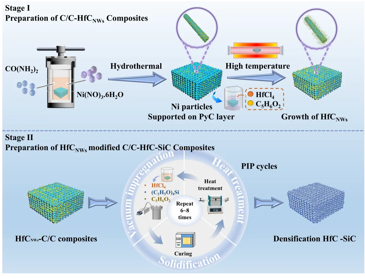
Figure 1. Preparation process of HfCNWs modified C/C-HfC-SiC composites with different HfC/SiC ratios.
2.3. Ablation Test
Ablation tests were conducted using an oxyacetylene flame with a 2.4 MW/m2 heat flow density. The inner diameter of the oxyacetylene torch nozzle was 2 mm, positioned at a stand-off distance of 10 mm from the sample surface. Three C/C-HfC-SiC composite samples (30 mm in diameter and 10 mm in thickness) were subjected to flame ablation for 60 s. The flow rates of O2 and C2H2 were maintained at 0.244 L/s and 0.167 L/s, with corresponding pressures of 0.4 MPa and 0.095 MPa, respectively. During the experiments, the surface temperature of the samples was monitored using a two-color infrared thermometer (Raytek MR1SCSF, Raytek Corporation, Santa Cruz, CA, USA). The mass and linear ablation rates were calculated according to Equations (1) and (2), respectively.
|
|
( 1 ) |
|
|
( 2 ) |
where m0 and m1 are the mass of the sample before and after ablation; l0 and l1 are the thickness of the sample before and after ablation, and Δt is the ablation time.
2.4. Characterization
The phase composition of the samples was characterized using X-ray diffraction (XRD, D8 ADVANCE-A25, Bruker, Karlsruhe, Germany). The morphology of the samples was observed using a scanning electron microscope (SEM, S-4800, Hitachi, Tokyo, Japan). The microstructure was analyzed using a transmission electron microscope (TEM, Tecnai G2 F20S-TWIN, ThermoFisher, Hillsboro, OR, USA). The porosity and density of the composites were measured using the Archimedes displacement method. Qualitative analysis of the elements in the samples was performed using an X-ray fluorescence spectrometer (XRF, RIGAKU ZSX Priums, Rigaku Corporation, Tokyo, Japan). Real-time depth of field and three-dimensional images of the samples were observed using a super-depth-of-field microscope (SHM, D8 ADVANCE-A25, Keyence, Osaka, Japan).
3. Results and Discussion
3.1. Microstructure of HfCNWs and C/C-HfC-SiC Composites
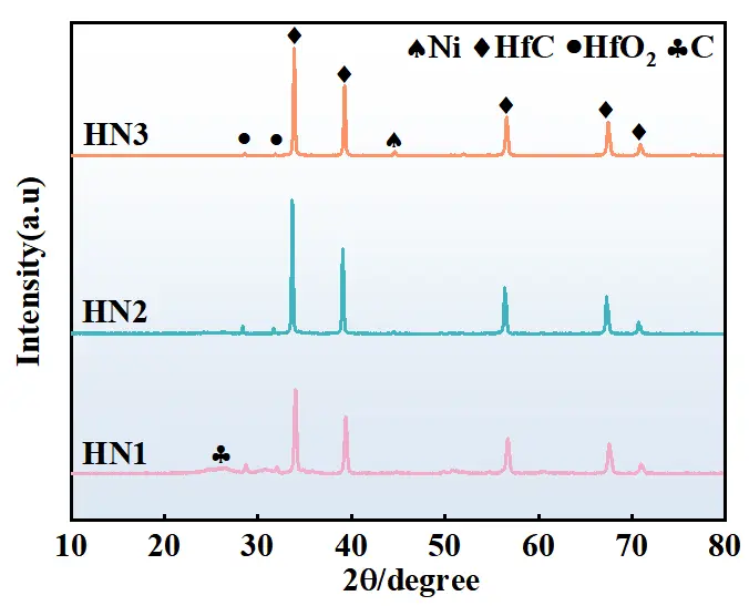
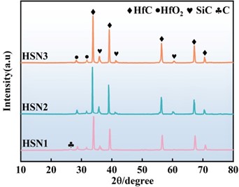
Figure 2 shows the XRD patterns of C/C-HfCNWs composites prepared using different Ni loading levels as the Ni source at a heat treatment temperature of 1500 °C. The XRD patterns reveal that all samples exhibit sharp HfC characteristic peaks at the diffraction positions corresponding to the standard card (PDF No. 65-8750), indicating the synthesis of well-crystallized cubic-phase HfCNWs. As the Ni loading increases, the intensity of the HfC diffraction peaks significantly enhances, while the diffraction peaks of HfO2 and C gradually weaken until they disappear. This trend in the XRD patterns confirms that Ni effectively catalyzes the carbon thermal reduction reaction, promotes the consumption of HfO2, and drives the growth of HfC crystals, thereby significantly increasing the yield of nanowires (consistent with the results in Figure 3(c4).
Figure 3 shows the SEM images of carbon fibers with different Ni loadings after heat treatment at 500 °C (Figure 3(a1–c1)) and the as-prepared C/C-HfCNWs composites (Figure 3(a2,a3–c2,c3)). The Ni loading content of the three samples in Figure 3(a1–c1) was quantitatively analyzed using the density change method. The original low-density C/C substrate had a density of 0.8 g/cm3. After Ni deposition, the densities of the modified samples N1, N2, and N3 were 0.812 g/cm3, 0.835 g/cm3, and 0.863 g/cm3, corresponding to Ni loading mass fractions of 1.50 wt%, 4.38 wt%, and 7.88 wt%, respectively.
Further observation of the morphology of the samples after heat treatment at 500 °C revealed that the Ni particles on the surface of sample N1 were relatively small, with an average diameter of less than 0.5 μm (Figure 3(a1)). Sample N2 exhibited moderately sized Ni particles, approximately 1–3 μm in diameter (Figure 3(b1)). In contrast, the surface of sample N3, which had the highest Ni loading, was covered with a large number of Ni particles ranging from 2 to 5 μm in size (Figure 3(c1)).
After heat treatment at 1500 °C for 2 h, the morphology of the C/C-HfCNWs composites underwent significant changes. In the HN1 sample with the lowest Ni loading (Figure 3(a2,a3)), the yield of HfCNWs was low, with only sporadic distribution. Most of the HfC existed as bulk ceramic coatings on the fiber surface, and the nanowires were merely a few micrometers in length, indicating that the low Ni content was insufficient to effectively convert HfC ceramic into a nanowire structure. When the Ni loading increased to 4.38 wt% (HN2 sample, Figure 3(b2,b3)), the yield of HfCNWs increased significantly. HfC ceramic particles were observed to coexist between the fibers, with most nanowires growing from the same Ni particle, exhibiting a typical prismatic morphology and lengths of approximately 5–10 μm. Figure 3(b4) indicates an average diameter of about 388 nm. As the Ni loading was further increased to 7.88 wt% (HN3 sample, Figure 3(c2,c3)), the HfCNWs showed an uneven, clustered distribution. The yield increased slightly, accompanied by the generation of a large number of nanoscale HfC particles. The average diameter of the nanowires increased to approximately 580 nm (Figure 3(c4)), while their length decreased to 2–5 μm, resulting in a shorter and thicker morphology.
The above results indicate that an appropriate amount of Ni can effectively promote the growth of HfCNWs. However, when the Ni content exceeds a critical value, the molten Ni aggregates at high temperatures to form larger alloy droplets. This aggregation of molten Ni into larger alloy droplets leads to a reduced saturation of the eutectic liquid phase, disrupts the vapor-liquid-solid (VLS) growth mechanism, and triggers multi-dimensional growth behavior. Consequently, the aspect ratio of the nanowires decreases, and the formation of nanoscale HfC particles is promoted.
Figure 4 shows the typical TEM microstructural characterization results of HfCNWs. Figure 4a displays a high-resolution TEM image of the nanowires, exhibiting excellent crystalline quality and surface morphology, with a smooth surface and no obvious structural defects. Notably, a uniformly thick HfOC oxide layer (5–10 nm) was observed on the surface of the nanowires, which was analyzed to be caused by minor reactions between the sample and oxygen in the environment during cooling. The prepared HfCNWs exhibit high crystallinity, with clear lattice striations corresponding to the (111) crystal plane of face-centered cubic (fcc) HfC. Quantitative measurements show that the spacing of this crystal plane is 0.27 nm, which is in good agreement with the (111) crystal plane spacing of HfC (0.266 nm) in the standard card (JCPDS No. 39-1491), further validating the crystalline structure characteristics of the product.
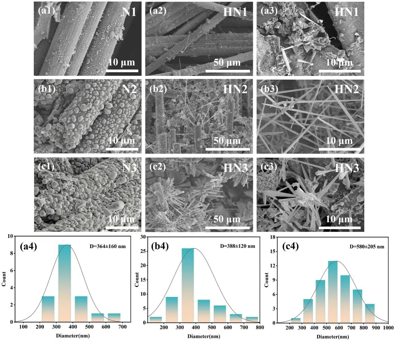
Figure 3. SEM images of (a1–c1) carbon fibers with different Ni loadings after heat treatment at 500 °C and (a2,a3–c2,c3) the resulting C/C-HfCNWs composites; (a4–c4) shows the corresponding diameter distribution of the HfCNWs in (a3–c3).
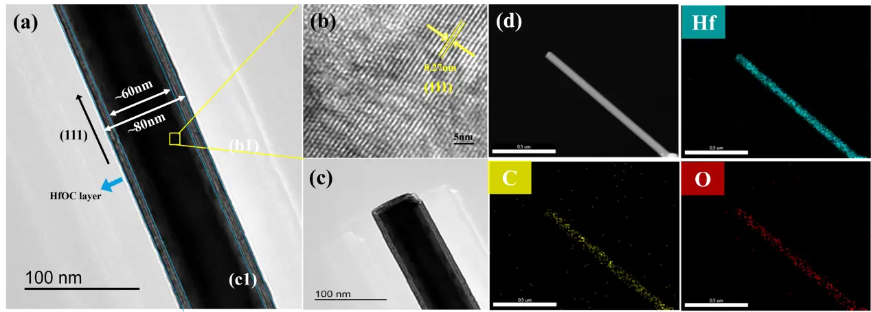
Figure 4. Microstructure of HfCNWs (a–c) TEM images; (d) Elemental distribution maps corresponding to C, Hf, and O elements.
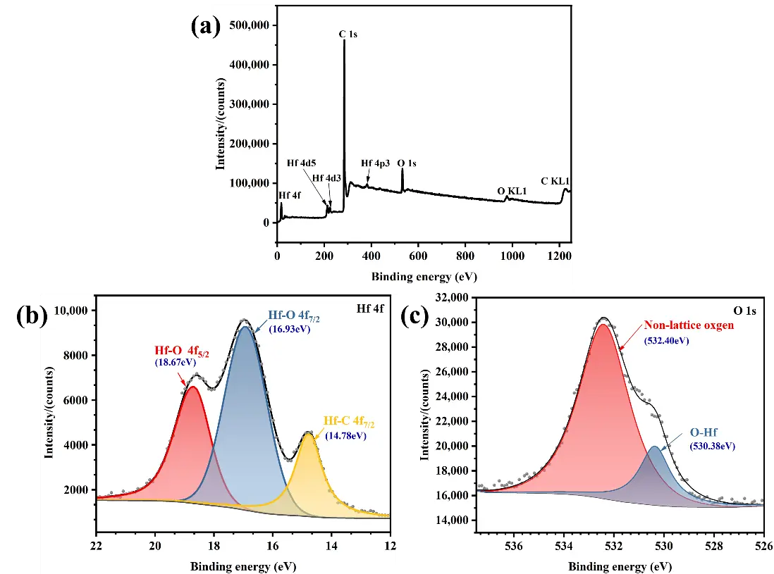
To further investigate the surface composition of HfCNWs and the chemical bonding between elements, XPS analysis was performed. Figure 5c shows the XPS spectrum of HfCNWs, clearly revealing characteristic peaks of Hf, C, and O, thereby elucidating the chemical composition of the surface and the bonding state between elements. The origin of the O element has two possible explanations: first, the formation of HfCxOy solid solutions during the carbon thermal reduction process; second, surface oxidation of the nanowires caused by oxygen-containing substances in the high-temperature atmosphere furnace after the carbon thermal reduction process. Further detailed fitting analysis of the Hf 4f and O 1s spectra was conducted to understand the bonding states of each element. The relevant results are shown in Figure 5a,b. Hf exhibits two bonding states: the Hf-C bond at 14.78 eV and the Hf-O bonds at 16.93 eV and 18.67 eV. The analysis of the O 1s spectrum indicates that oxygen primarily exists in two forms: amorphous oxygen at 532.4 eV and O-Hf bonds at 530.38 eV. This XPS analysis result suggests that the oxygen layer on the surface of HfCNWs primarily exists in the form of O-Hf bonds, with higher oxygen concentrations near the edges of the HfCNWs.
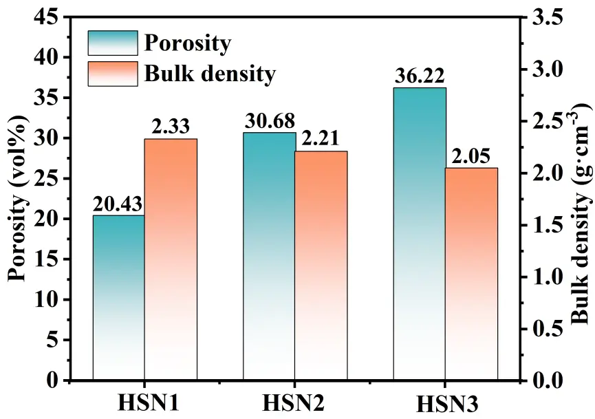
As shown in Figure 8, the porosity and bulk density data of the three composites indicate a clear correlation between the macroscopic properties of the materials and the microscopic morphological characteristics depicted in Figure 7: The HSN1 sample exhibits a dense structure (containing only a small number of microdefects) due to the homogeneous nucleation characteristics of HfC and SiC grains with small and uniformly distributed grain sizes, corresponding to its lowest porosity of 20.43% and highest bulk density of 2.33 g·cm−3; The HSN2 sample exhibits submicron-sized gaps caused by sintering shrinkage and small pores formed by the accumulation of nanowires under heterogeneous nucleation mechanisms. Although the strong capillary forces imparted by the small pores can promote precursor penetration, the additional pores still result in a significantly higher porosity and corresponding decrease in bulk density compared to HSN1. The HSN3 sample exhibited distinct cracks and pores due to continuous epitaxial growth and grain merging. The entrances to large pores were prematurely sealed due to preferential precursor deposition, weakening capillary forces, and obstructing internal penetration. Additionally, the increased size and reduced uniformity of HfC grains resulted in the highest porosity and lowest bulk density. Meanwhile, as the number of PIP cycles increases, the number of pores generated by the erosion of the PyC layer on the carbon fiber surface under Ni catalysis increases. Although the HfC-SiC composite ceramic phase can partially fill such pores, the structural degradation from HSN1 to HSN3 dominates the overall trend of continuously increasing porosity and gradually decreasing bulk density.
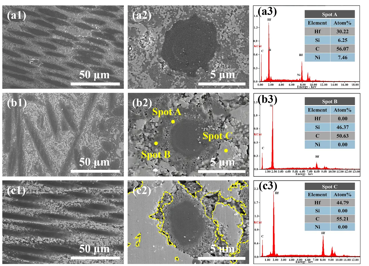
Figure 7. Microstructural morphology of HfCNWs modified C/C-HfC-SiC composites: (a1,a2) HSN1; (b1,b2) HSN2; (c1,c2) HSN3; (a3–c3) energy-dispersive X-ray spectroscopy (EDS) spectra of HSN2.
3.2. Ablation Behavior
This study investigated the ablation resistance of three composites, designated as HSN1, HSN2, and HSN3, using oxygen-acetylene torch tests under a heat flux of 2.4 MW/m2 for 60 s. The macroscopic morphology and distribution of oxides after ablation are presented in Figure 9a. Based on macro-photographs obtained after ablation, the surface oxide coating coverage (area ratio) was quantitatively analyzed using Image J software (Version 1.53t). During testing, the ablation flame was perpendicular to the composite surface, resulting in the formation of oxide protective layers with varying degrees of development, typically differentiated into central and peripheral regions. The area and integrity of the oxide layer can, to some extent, reflect the ablation resistance of the composites. According to macroscopic images and oxide layer distribution results, the oxide layer area ratio for the HSN1 composite was measured as 51.3%. Distinct ablation pits are observed in the central ablation zone of this material. High-speed, high-temperature gas flow expelled ablation products from the center to the transition region, suggesting that the HSN1 composite exhibits the lowest ablation resistance among the samples. The oxide layer area of HSN3 composites is 56.8%. The oxide layer on the ablation surface is not continuous. It shows signs of cracking due to the oxide layer being peeled off by the ablation flame in the central region of the ablation surface. However, in the HSN2 composites, no obvious structural damage was observed at the ablation center, and the ablation surface was covered by an oxide layer with certain porosity and relative continuity, indicating that the HSN2 composites exhibit excellent ablation resistance under high-temperature conditions. Based on the above research results, the HSN2 composites formed a larger, more stable ablation protective layer during the 60-s ablation process.
The XRD analysis results of the ablation surface materials (Figure 9b) indicate that the ablation products are primarily composed of SiO2 and HfO2. The XRD spectrum of the HSN2 composites exhibits higher-intensity SiO2 and HfSiO4 diffraction peaks compared to the other two composites. HfSiO4 is a high-viscosity, low-volatility substance that can stabilize HfO2 during ablation, thereby helping to suppress phase transformations and volume expansion during cooling. This indicates that during ablation, the sample can more effectively retain Si elements on the ablation surface, participating in the formation of a protective oxide layer, which is manifested macroscopically as a larger oxide coverage area (Figure 9a).
Based on the three-dimensional morphology of the ablation surface, we conducted a quantitative comparison of the ablation depth, linear ablation rate (LAR), mass ablation rate (MAR), and temperature evolution curves for the three composites HSN1, HSN2, and HSN3 (Figure 10a–c). Analysis of the surface topography curves indicates that the oxidation layer of HSN1 composites has significantly insufficient erosion resistance, as evidenced by the formation of prominent ablation pits on the surface (Figure 10a), resulting in a much higher amplitude of depth fluctuations in its surface topography curve compared to HSN2 and HSN3. Such structural defects exacerbate the oxidation reaction between the ceramic matrix and carbon fibers. In contrast, the surface roughness curve of HSN2 is smoother, indicating the formation of a more uniform and complete oxide layer. This oxide layer not only hinders oxygen diffusion but also resists the shear peeling effect of high-speed gas flow.
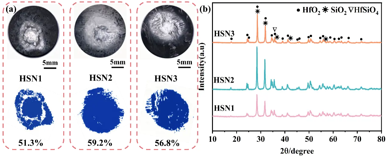
Figure 9. (a) Macro morphology and corresponding oxide layer distribution of HfCNWs modified C/C-HfC-SiC composites after ablation; (b) XRD patterns.
Erosion resistance performance analysis shows that the three composites exhibit significantly differentiated erosion behavior (Figure 10b). The HSN1 sample exhibits the highest linear ablation rate (21.43 µm/s) and mass ablation rate (1.31 mg/(s·cm2)), which is closely related to the porous oxide layer structure formed on its surface. Figure 10a shows that this sample simultaneously exhibits intense volatilization of SiO2 and discontinuous peeling of the HfO2 oxide layer during ablation. In contrast, HSN2 demonstrated the most outstanding ablation resistance, with linear ablation rates (5.50 µm/s) and mass ablation rates (0.47 mg/(s·cm2)) reduced by 74.3% and 64.1%, respectively, compared to HSN1. Microstructural characterization (Figure 10b) confirmed that this performance improvement was primarily attributed to the formation of a complete and dense oxide protective layer during ablation, which effectively blocked oxygen diffusion into the substrate and facilitated a gradual transition from the ablation edge to the center.
Notably, the ablation resistance of the HSN3 sample lies between that of HSN1 and HSN2, with its linear ablation rate (6.25 µm/s) and mass ablation rate (0.88 mg/(s·cm2)) increasing by 13.6% and 87.2%, respectively, compared to HSN2. Based on the microstructural analysis in Figure 7(c2), this performance degradation can be attributed to the porous structure formed within the material due to the increased diameter of the nanowires. This pore network provides pathways for oxygen diffusion, leading to sustained oxidative reactions within the material. Nevertheless, the ablation performance of HSN3 remains significantly superior to that of HSN1, confirming the positive role of HfCNWs in enhancing the material’s ablation resistance.
Figure 10c shows the temperature change curves of the three composites HSN1, HSN2, and HSN3 in the ablation center region. Within the initial 0 to 30 s of ablation, the surface temperature of the material exhibits a sharp increase, which is attributed to the exothermic oxidation reaction between HfC and SiC. However, the initially formed oxide layer is not yet continuous, resulting in poor thermal insulation of the substrate and rapid heat accumulation. Once the oxide layer forms, the rise in temperature slows down and gradually stabilizes. Ultimately, the peak surface temperatures of HSN1, HSN2, and HSN3 were measured to be 2412 °C, 2302 °C, and 2346 °C, respectively. Compared to HSN1, the increased presence of HfCNWs significantly suppresses the rise in surface temperature during ablation. The core mechanism lies in the fact that HfCNWs act as miniature heat pipes embedded in the matrix, establishing anisotropic, efficient heat transport pathways that rapidly redirect concentrated surface heat flows into the material’s interior, preventing localized heat accumulation. This efficient heat transport mechanism also explains why the oxide layer coverage of HSN2 and HSN3 is broader than that of HSN1. However, the peak temperature of HSN3 is slightly higher than that of HSN2, primarily because the large spacing between HfCNWs with larger diameters results in discontinuous heat flow paths, making it easier for heat to accumulate on the surface. In contrast, the smaller-diameter HfCNWs in HSN2 form denser and more uniformly distributed heat conduction channels, thereby achieving more efficient heat dissipation.
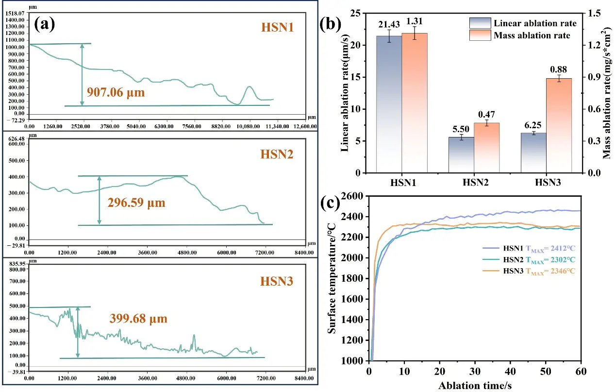
Figure 10. (a) Super-depth-of-field image; (b) ablation rate diagram; (c) temperature evolution curve diagram of HfCNWs modified C/C-HfC-SiC composites after ablation.
To further elucidate the mechanisms underlying the influence of different microstructures on ablation behavior, we conducted a detailed SEM analysis of the morphological differences in the ablation centers of HSN1, HSN2, and HSN3. The microstructures and EDS spectra of the ablation centers of the three composites are shown in Figure 11. In the ablation center regions, areas of oxide peeling and oxide retention were observed. Figure 11a shows the oxide peeling region of HSN1. Due to the highest temperature and most severe mechanical erosion in the ablation center region, the carbon fibers have been almost completely eroded by the ablation flame. As shown in Figure 11(a3), the SEM analysis indicates that the connectivity and mechanical integrity of the HfO2 framework have been damaged, with pore sizes ranging from 5 to 15 μm, forming micron-sized open channels that provide pathways for rapid oxygen diffusion and continued oxidation of the carbon fibers. Under the action of high-speed flames, molten SiO2 is blown away, forming holes and cracks. Although HfO2 nanowires (HfO2NWs) can resist mechanical erosion from high-speed flames and act as a thermal barrier, due to the low content of nanowires, there is insufficient molten SiO2 to fill the holes, and the loose network structure severely limits the ability to block oxygen penetration. On the ablated surface of HSN2 (Figure 11b), HfO2NWs intertwine with oxides to form a protective layer on the carbon fiber surface, effectively preventing direct flame erosion of the fibers. EDS analysis of Spot C in Figure 11(a3) reveals no residual Si phase, suggesting that under high-temperature and high-pressure conditions, HfCNWs decompose into HfO2 particles that fill the pores, with some melting and intertwining to form a network-like skeletal structure, which demonstrates excellent shear resistance. Figure 11(b2) further shows that the oxide framework formed by HfO2NWs not only acts as an anchor for the liquid phase but also bridges pores and cracks to inhibit their propagation, exhibiting excellent shear resistance. This structure significantly enhances the stability of the ablation layer, drastically reduces oxygen diffusion pathways, and consequently lowers the mass ablation rate. Combined with the EDS results in Figure 11(b4), the densely formed Hf-Si-O glass phase protective layer synergistically interacts with HfO2NWs and HfO2 particles, enabling HSN2 to exhibit outstanding ablation resistance. The ablation surface of HSN3 (Figure 11c) exhibits a discontinuous oxide distribution with pores, indicating severe ablation damage, with the oxide layer forming a porous HfO2 structure. High-magnification morphology observations reveal that the aspect ratio of HfCNWs decreases after oxidation to HfO2NWs. This structural change is attributed to the diffusion and rearrangement of surface atoms under ultra-high-temperature and oxygen-rich conditions. Consequently, gaps of 1–5 μm exist between the resulting HfO2NWs. The limited specific surface area and increased curvature radius of these short, thick nanowires lead to a low network density upon interlocking. Such a low-density network is unable to effectively constrain the coarsening and growth of HfO2 particles during sintering, ultimately resulting in a loose and porous morphology. Additionally, the insufficient amounts of SiO2 and HfSiO4 cause the oxide layer to lose its self-healing ability for the gaps, further exacerbating erosion damage.
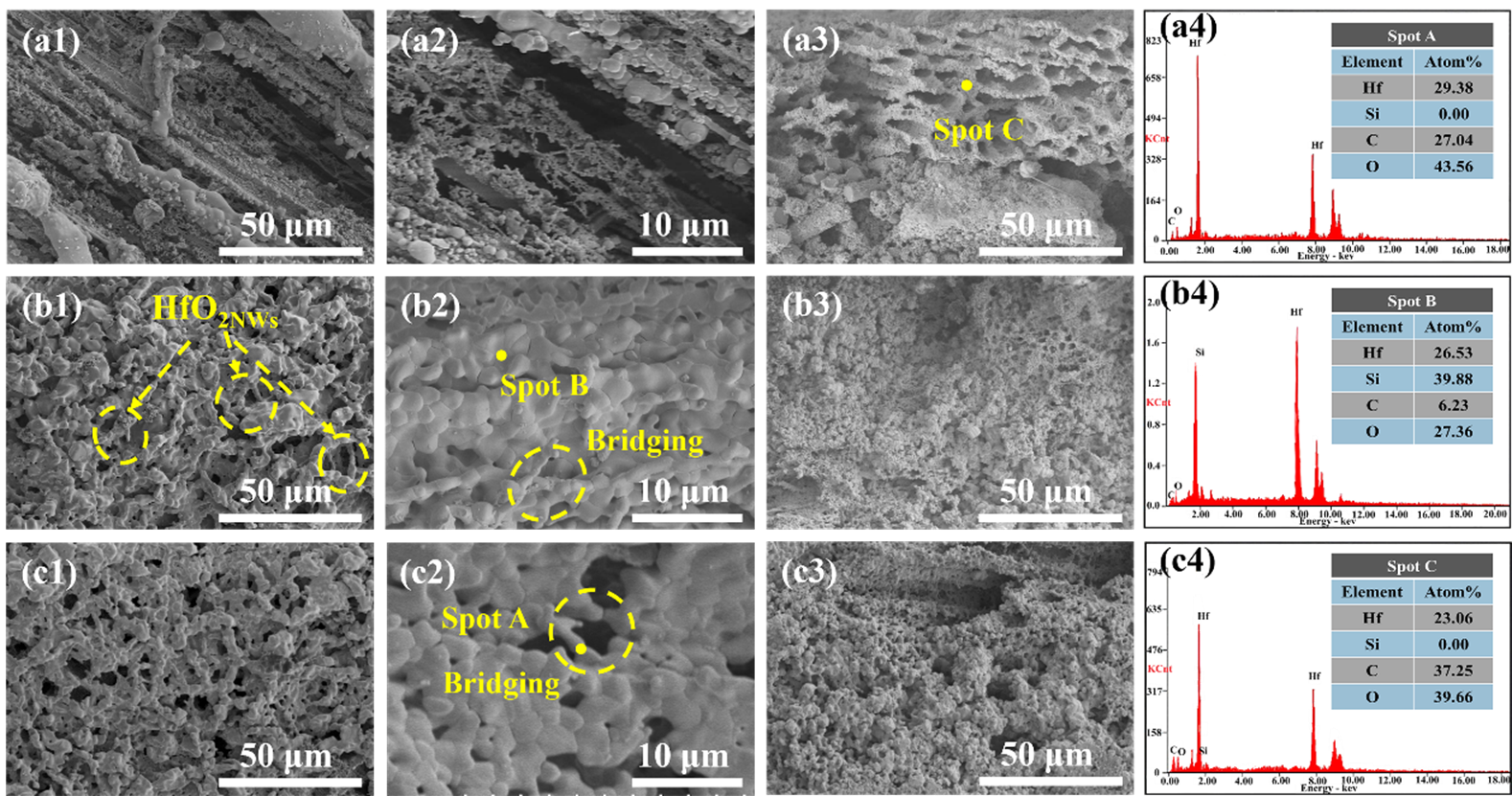
Figure 11. Microstructural morphology of the ablation center zone (a1,a2) HSN1; (b1,b2) HSN2; (c1,c2) HSN3; ablation center cross-section (a3–c3) and EDS spectra (a4–c4) of HSN1-HSN3 for HfCNWs modified C/C-HfC-SiC composites.
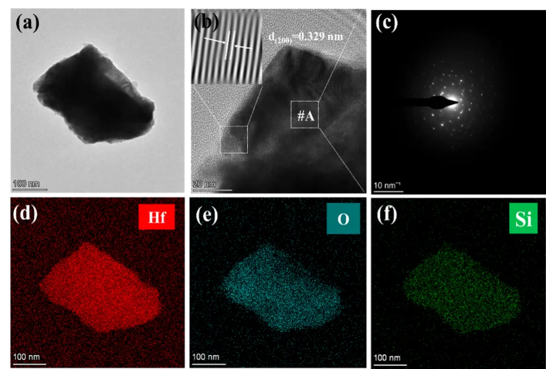
Figure 12. TEM images of oxide particles in HfCNWs modified C/C-HfC-SiC composites: (a) TEM image; (b) HRTEM; (c) selected area electron diffraction pattern of (b); (d–f) EDS energy dispersive spectra.
3.3. Ablation Resistance Mechanism
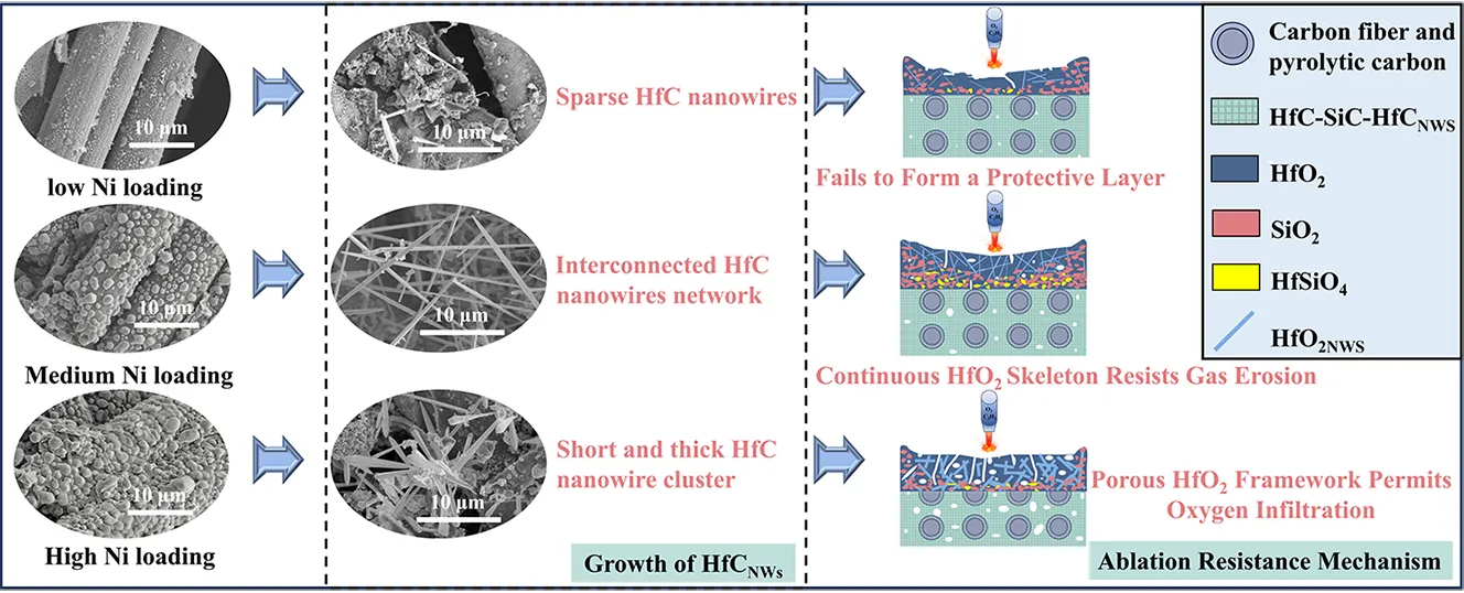
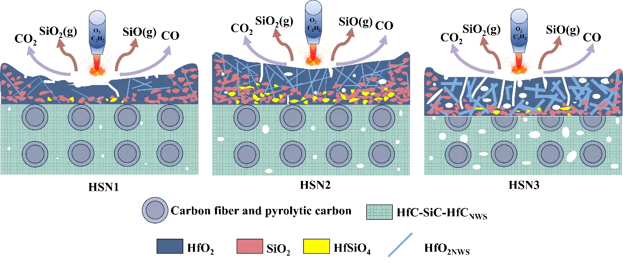
During the oxygen-acetylene ablation process, HfCNWs/C/C-HfC-SiC composites modified with different Ni loadings (HSN1, HSN2, HSN3) exhibit significant differences in ablation resistance, primarily attributed to the structural evolution of their oxide layers and variations in erosion resistance. The schematic diagram illustrating the morphological and microstructural evolution mechanisms under oxygen-acetylene ablation is shown in Figure 13.
Owing to its inferior resistance to mechanical erosion, the porous oxide scale on HSN1 spalled off rapidly under the high-temperature gas flow during the initial ablation stage. This oxide scale primarily consisted of HfO2 and SiO2 formed from the oxidation of HfC and SiC. The SiO2 in the ablation center region is extensively consumed due to evaporation and erosion, leaving only a loose, porous HfO2 skeletal structure. This skeleton undergoes structural damage under thermal shock and phase transformation stresses, with the resulting flaking and formed pores providing pathways for oxygen intrusion, promoting internal oxidation of the material, and thus exhibiting the weakest ablation resistance.
In contrast, HSN2 benefits from a dense HfCNWs network structure and a robust HfO2 porous skeleton formed by the oxidation of HfC particles, enabling its ablation core region to effectively resist mechanical erosion and thermal shock. The dense HfO2 skeleton confers excellent resistance to flaking and inhibits the volatilization of molten SiO2. Under high-temperature conditions, the SiO2 liquid phase further fills defects in the HfO2 framework, promoting the formation of high-viscosity, low-volatility HfSiO4 through solid-liquid phase reactions, thereby enhancing the stability of the HfO2(s)-SiO2(l) system. The resulting HfSiO4 has a high viscosity, enabling it to flow and fill the spaces between HfO2 grains [17,38]. This not only seals structural defects caused by phase transitions but also significantly enhances the overall densification of the oxide layer. Additionally, the HfCNWs network structure forms efficient heat transfer channels within the ablation layer, reducing surface temperature and alleviating thermal stress accumulation, thereby significantly improving the material’s ablation resistance.
For HSN3, the larger diameter of HfCNWs leads to increased internal voids, forming a loose network structure. During ablation, this structure cannot effectively bind ceramic particles, resulting in insufficient density of the generated HfO2 framework and difficulty in blocking oxygen diffusion. Additionally, at high temperatures, the viscosity of molten SiO2 decreases, making it susceptible to erosion by high-speed gas flows. This results in incomplete solid-liquid phase reactions between HfO2 and SiO2, reducing HfSiO4 formation. Consequently, the ablation center of HSN3 exhibits a porous oxide layer, with ablation resistance significantly inferior to that of HSN2.
In summary, the superior ablation resistance of HSN2 stems from its dense HfCNWs network structure, robust HfO2 framework, and HfSiO4 formation, while HSN1 and HSN3 exhibit reduced ablation resistance due to insufficient mechanical strength and structural porosity, respectively, leading to protective layer failure. The developed HSN2 composite demonstrates great potential for application in thermal protection systems of hypersonic vehicles. Future work will focus on optimizing its high-temperature stability under prolonged exposure and scaling up the manufacturing process for industrial production.
4. Conclusions
This study employed a hafnium tetrachloride-furfuryl alcohol-ethanol polymer as a precursor and utilized Ni as a catalyst to grow HfCNWs in-situ within low-density C/C composites. Three C/C-HfC-SiC composites were subsequently fabricated via the PIP process.
-
With an increasing concentration of the Ni precursor, the Ni loading on the carbon fiber surface rose concomitantly from 1.50 wt% to 7.88 wt%. Correspondingly, the morphology of the deposited nickel evolved from submicron-sized particles into a continuous micron-scale coating (2–5 μm) that fully encapsulated the fibers.
-
The Ni loading level dictates the morphology and yield of the HfCNWs. An increase in Ni loading from 1.50 wt% to 4.38 wt% transforms the nanowires from a sparse, slender geometry (diameter: ~364 nm, length: <10 μm) to a high-density, multi-oriented network, with lengths extending to 20–50 μm. Conversely, a further increase to 7.88 wt% leads to the coalescence of excess Ni into large alloy droplets at high temperatures, which promotes the growth of short, thick nanowire clusters (diameter: ~580 nm, length: 5–10 μm) alongside a considerable amount of granular by-products, thereby markedly diminishing the overall aspect ratio.
-
The ablation performance of the material is directly linked to the yield and structure of the HfCNWs. At a Ni loading of 4.38 wt%, a HfCNWs network formed within the composite, which transformed into a continuous HfO2 skeleton during ablation, effectively resisting high-speed gas flow scouring. Simultaneously, molten SiO2 infiltrated this skeleton and reacted to form a high-viscosity HfSiO4 phase, sealing microcracks and pores. This synergistic effect significantly enhanced the density and stability of the oxide layer, resulting in the optimal ablation resistance (mass ablation rate: 0.47 mg·s−1·cm−2; linear ablation rate: 5.50 μm·s−1). In contrast, a low Ni loading (1.50 wt%) yielded sparse and slender nanowires, which were insufficient to form a protective layer, leading to the highest ablation rates. Conversely, a high Ni loading (7.88 wt%) resulted in coarsened nanowires with a low aspect ratio, producing a porous HfO2 framework that provided pathways for oxygen diffusion.
-
This work elucidates the influence of the quantity and diameter of HfCNWs on the ablation resistance of the composite. It confirms that introducing a HfCNWs network within a specific range of density and diameter is pivotal for forming a self-healing, highly stable oxide layer. This study provides a foundation for the design of HfCNWs-reinforced C/C-HfC-SiC composites, thereby facilitating their engineering application in aerospace thermal protection systems.
Author Contributions
Writing—Original Draft Preparation, Q.C.; Writing—Review&Editing, C.L., H.O.; Conceptualization, Q.C., C.L., H.O., Z.C., T.S., Q.W.; Validation, C.L., H.O., Y.L., J.L., M.H.; Investigation, Q.C., Z.C., J.L., S.W.; Supervision, C.L., H.O., Y.L.; Funding Acquisition, H.O.; Methodology, Q.C., L.W., L.B.
Ethics Statement
Not applicable.
Informed Consent Statement
Not applicable.
Data Availability Statement
Data will be made available on request.
Funding
This research was supported by the National Natural Science Foundation of China (Grant No. 52173299, 52372087), Natural Science Foundation of Shaanxi Province (Grant No. 2021JZ-51).
Declaration of Competing Interest
The authors declare that they have no known competing financial interests or personal relationships that could have appeared to influence the work reported in this paper.
References
- Kane KA, Pint BA, Mitchell D, Haynes JA. Oxidation of ultrahigh temperature ceramics: Kinetics, mechanisms, and applications. J. Eur. Ceram. Soc. 2021, 41, 6130–6150. [Google Scholar]
- Wan Z, Ma L, Wang X, Sun Z, Yang C. Aerothermoelastic problems of hypersonic vehicles and their recent research progress. Acta Astronaut. 2025, 236, 982–1011. [Google Scholar]
- Wang C, Song YM, Yan T, Xiao S, Zhu LQ. Data-driven model for predicting surface heat flux of hypersonic vehicles based on eXtreme Gradient Boosting. Phys. Fluids 2025, 37, 085173. [Google Scholar]
- Hu F, Wang J, Sui Z, Lin G, Zhao W, Jin H, et al. A review on research progress of large area thermal protection structures for hypersonic vehicles. Acta Astronaut. 2025, 232, 541–556. [Google Scholar]
- Cheng T. Ultra-high-temperature mechanical behaviors of two-dimensional carbon fiber reinforced silicon carbide composites: Experiment and modeling. J. Eur. Ceram. Soc. 2020, 41, 2335–2346. [Google Scholar]
- Cheng T. Understanding the ultra-high-temperature mechanical behaviors of advanced two-dimensional carbon-carbon composites. Ceram. Int. 2020, 46, 21395–21401. [Google Scholar]
- Song L, Meng S, Zhang Y, Yang F, Xie W. Exploring the multi-scale evolution mechanism of the ultra-high-temperature mechanical behaviour of carbon/carbon composites. J. Alloys Compd. 2025, 1010, 177449. [Google Scholar]
- Fu Q, Zhang P, Zhuang L, Zhou L, Zhang J, Wang J, et al. Micro/nano multiscale reinforcing strategies toward extreme high-temperature applications: Take carbon/carbon composites and their coatings as the examples. J. Mater. Sci. Technol. 2022, 96, 31–68. [Google Scholar]
- Xie A, Yang F, Zhang B, Yi M, Ge Y, Wang X. Isothermal and cyclic oxidation behavior of a sandwiched coating for C/C composites. Ceram. Int. 2021, 47, 32505–32513. [Google Scholar]
- Wu X, Yang B, Li Y, Yu S. High temperature oxidation behaviors of C/C composites with SiOC coatings. J. Eur. Ceram. Soc. 2024, 44, 3537–3543. [Google Scholar]
- Zhu S, Zhang G, Bao Y, Sun D, Zhang Q, Meng X, et al. Progress in preparation and ablation resistance of ultra-high-temperature ceramics modified C/C composites for extreme environment. Rev. Adv. Mater. Sci. 2023, 62, 20220276. [Google Scholar]
- Zhao Z, Li K, Li W. Ablation behavior of ZrC-SiC-ZrB2 and ZrC-SiC inhibited carbon/carbon composites components under ultrahigh temperature conditions. Corros. Sci. 2021, 189, 109598. [Google Scholar]
- Zhang M, Liu T, Hu D, Fu Q. Ablation behavior of UHTCs carbide-modified C/C composites in extreme aerobic environments (3000 °C): Evolution mechanisms of oxides film structure. Corros. Sci. 2025, 253, 113036. [Google Scholar]
- Zhang M, Hu D, Fu Q. Thermal protection mechanism of UHTCs-modified C/C composites in high temperature gas scouring coupling environments. Compos. Part B Eng. 2025, 302, 112550. [Google Scholar]
- Kou S, Mao Y, Ma J, Ma Y, Yang S, Liu X, et al. Microstructure evolution and properties of Hf/Zr-based UHTCs modified C/C composites prepared by reactive melt infiltration method. J. Eur. Ceram. Soc. 2023, 44, 3610–3621. [Google Scholar]
- Jiao X, Tan Q, He Q, Qing M, Wang Y, Yin X. Cyclic ablation behavior of mullite-modified C/C-HfC-SiC composites under an oxyacetylene flame at about 2400 °C. J. Eur. Ceram. Soc. 2023, 43, 4309–4321. [Google Scholar]
- Jiao X, He Q, Feng J, Tan Q, Wang Y, Yin X. Comparison of the ablation resistance of mullite modified C/C-SiC-HfC and C/C-SiC-HfC composites under oxyacetylene flame of 2.38 MW/m2 heat flux. Ceram. Int. 2023, 49, 36580–36589. [Google Scholar]
- Zhang M, Hu D, Fu Q. Ablation resistant behavior of silicide modified HfB2-SiC coating on graphite by spark plasma sintering: Role of MeSi2 addition. J. Eur. Ceram. Soc. 2024, 44, 6286–6297. [Google Scholar]
- Ren J, Lv C, Duan Y, Zhang Y, Zhang J. Microstructure and ablation performance of HfC/PyC core-shell structure nanowire-reinforced Hf1−xZrxC coating. J. Eur. Ceram. Soc. 2021, 41, 7450–7463. [Google Scholar]
- Tian S, Zhou L, Liang Z, Yang Y, Wang Y, Qiang X, et al. 2.5 D carbon/carbon composites modified by in situ grown hafnium carbide nanowires for enhanced electromagnetic shielding properties and oxidation resistance. Carbon 2020, 161, 331–340. [Google Scholar]
- Yang X, Chen Y, Zhang C, Duan G, Jiang S. Electrospun carbon nanofibers and their reinforced composites: Preparation, modification, applications, and perspectives. Compos. Part B Eng. 2023, 249, 110386. [Google Scholar]
- Shi X, Jin X, Lin H, Jing J, Li L, Wang C. Joining of SiC nanowires-toughened SiC coated C/C composites and nickel based superalloy (GH3044) using Ni71CrSi interlayer. J. Alloys Compd. 2017, 693, 837–842. [Google Scholar]
- Li B, Li H, Yao X, Zhu X, Liu N. Preparation and ablation resistance of ZrC nanowires-reinforced CVD-ZrC coating on sharp leading edge C/C composites. Appl. Surf. Sci. 2022, 584, 152617. [Google Scholar]
- Fu Y, Zhang Y, Zhang J, Li T, Chen G. Mechanical properties and ablation resistance of HfC nanowire modified carbon/carbon composites. Ceram. Int. 2020, 46, 16142–16150. [Google Scholar]
- He Q, Li H, Yin X, Wang C, Lu J. Microstructure, mechanical and anti-ablation properties of SiCnw/PyC core-shell networks reinforced C/C–ZrC–SiC composites fabricated by a multistep method of chemical liquid-vapor deposition. Ceram. Int. 2019, 45, 20414–20426. [Google Scholar]
- Gu D, Liu B, Dong W, Li H, Yao X. Synthesis of the ZrC whiskers and the ablation mechanism of the ZrC whisker-toughened ZrC coating. Ceram. Int. 2024, 50, 54728–54736. [Google Scholar]
- Ren J, Zhang Y, Hu H, Zhang P, Fei T, Zhang L. HfC nanowires to improve the toughness and oxidation resistance of Si-Mo-Cr/SiC coating for C/C composites. Ceram. Int. 2016, 42, 14518–14525. [Google Scholar]
- Kagarice KJ, Magera GG, Pollard SD, Mackie WA. Cold field emission from HfC(310). J. Vac. Sci. Technol. B Microelectron. Nanometer Struct.Process.Meas. Phenom. 2008, 26, 868–871. [Google Scholar]
- Tian S, Li H, Zhang Y, Ren J, Qiang X, Zhang S. Hafnium carbide nanocrystal chains for field emitters. Appl. Surf. Sci. 2014, 305, 697–701. [Google Scholar]
- Yan N, Shi X, Li K, Fu Q, Xie W, Zhang H, et al. In-situ homogeneous growth of ZrC nanowires on carbon cloth and their effects on flexural properties of carbon/carbon composites. Compos. Part B Eng. 2018, 154, 200–208. [Google Scholar]
- Li J, Zhang Y, Fu Y, Fei T, Xi Z. A simple and efficient route to synthesize hafnium carbide nanowires by catalytic pyrolysis of a polymer precursor. Ceram. Int. 2018, 44, 13335–13340. [Google Scholar]
- Fu Y, Zhang Y, Yin X, Li T, Zhang J. Awl-like HfC nanowires grown on carbon cloth via Fe-catalyzed in a polymer pyrolysis route. J. Am. Ceram. Soc. 2020, 103, 3458–3465. [Google Scholar]
- Fu Y, Zhang Y, Ren J, Li T, Wang H. Large-scale synthesis of hafnium carbide nanowires via a Ni-assisted polymer infiltration and pyrolysis. J. Am. Ceram. Soc. 2019, 102, 2924–2931. [Google Scholar]
- Shahid M, Abbasi M, Yaqoob M, Haque RA, Iqbal MA. Techniques in the synthesis of organometallic compounds of Hafnium. Rev. Inorg. Chem. 2022, 42, 89–120. [Google Scholar]
- Cheng J, Wang X, Wang H, Shao C, Wang J. Preparation and high-temperature behavior of HfC–SiC nanocomposites derived from a non-oxygen single-source-precursor. J. Am. Ceram. Soc. 2017, 100, 5044–5055. [Google Scholar]
- Zhang B, Zhong F, Qiu X, Xu J, Hu M, Ou-Yang, J, et al. Hydrothermal synthesis of HfC whiskers and its toughening effect on ZrB2-HfO2 coatings. J. Solid State Chem. 2024, 329, 124384. [Google Scholar]
- Sun B, Li C, Ouyang H, Gao R, Shen T, Li Y. Synthesis of HfC nanowires on carbon fibers by a novel catalyst-assisted pyrolysis using HfCl4 as precursor. Ceram. Int. 2024, 50, 24901–24906. [Google Scholar]
- Guo R, Li L, Li Z, Zheng R, Ma C. Improved oxidation and ablation resistance of SiCf/SiC-HfB2 composites: Role of oxygen-blocking scale and protection mechanism. Ceram. Int. 2024, 50, 46377–46390. [Google Scholar]