Solid oxide fuel cells (SOFCs) represent a highly efficient and environmentally sustainable technology for direct conversion of chemical energy to electricity, applicable across stationary power generation and portable energy systems [
1,
2,
3]. A critical component of SOFCs is the anode, which facilitates fuel oxidation and charge transfer. Traditional Ni-yttria-stabilized zirconia (Ni-YSZ) cermet anodes, while effective for hydrogen oxidation, suffer from redox instability [
4], sulfur poisoning [
5], and severe carbon deposition when operated with hydrocarbon fuels such as methane [
6,
7,
8]. These drawbacks have spurred extensive research into alternative anode materials possessing high catalytic activity, structural stability, and carbon deposition tolerance. Over the past two decades, mixed ionic-electronic conductors (MIECs) have emerged as promising candidates for Ni-based SOFC anodes [
9,
10,
11,
12].
The double perovskite Sr
2Fe
1.5Mo
0.5O
6−δ (SFMO) demonstrates excellent electronic conductivity, redox stability, and sulfur resistance, positioning it as a viable anode material [
13,
14,
15,
16,
17]. However, its catalytic activity for methane electrooxidation remains suboptimal due to insufficient active sites for hydrocarbon activation and limited oxygen-ion mobility [
18,
19,
20]. For instance, Han et al. [
21] reported peak power densities of 0.63 W/cm
2 in hydrogen versus merely 0.01 W/cm
2 in methane at 800 °C using SFMO anodes. This performance gap significantly hinders SFMO’s commercial viability.
To address this, researchers have proposed the loading of nano-metal catalysts on perovskite surfaces, creating nano-metal/perovskite heterostructured anodes to enhance electrochemical performance [
22]. In this anode configuration, the mixed conductor perovskite oxides facilitate both oxygen ion and electron conduction, while the dispersed nano-metals provide high catalytic activity, comparable to that of traditional Ni-YSZ anodes [
23]. The conventional wet impregnation method is commonly utilized to fabricate the heterogeneous structural SOFC anodes. However, the nano-metals produced via this method demonstrate insufficient adhesion to the perovskite substrate, leading to detachment and agglomeration over prolonged operation. In recent years, the
in-situ exsolution technique has gained significant attention for generating heterostructured anodes [
24], as exsolved nanoparticles remain anchored securely within the perovskite lattice, imparting exceptional stability against coarsening during prolonged operation [
25,
26,
27,
28].
In this study, we developed a Sr
2Fe
1.3Ni
0.2Mo
0.5O
6−δ (SFNMO) perovskite via B-site Ni substitution and systematically investigated its
in-situ exsolution behavior and methane electrooxidation performance. This work establishes a strategic paradigm for designing high-performance, degradation-resistant SOFC anodes toward hydrogen carbon fuels.
2.1. Material Synthesis and Characterization
In this study, the SFMO and SFNMO perovskites were synthesized via solid-state reaction method [
29] and gel-sol method [
30], employing distinct precursors: carbonate/oxide reagents (SrCO
3, Fe
2O
3, (NH
4)
6Mo
7O
24·4H
2O, NiO) for solid-state synthesis versus nitrate salts (Sr(NO
3)
2, Fe(NO
3)
3·9H
2O, (NH
4)
6Mo
7O
24·4H
2O, Ni(NO
3)
2·6H
2O) for sol-gel synthesis. While all material characterizations employed solid-state synthesized powders, cell fabrication utilized sol-gel derived powders exclusively to enhance electrochemical performance—leveraging their reduced particle size and heightened reactivity. Phase purity and crystal structure of SFNMO powders were characterized by X-ray diffraction (XRD; Rigaku MiniFlex 500, Tokyo, Japan) using Cu-K
α radiation (λ = 1.5406 Å) with a scanning step of 0.01°. Morphological analysis of SFNMO powders and fuel cell microstructures was performed using field-emission scanning electron microscopy (FE-SEM; FEI Apreo S, Hillsboro, OR, USA). Chemical states of constituent elements were probed by X-ray photoelectron spectroscopy (XPS; Thermo Fisher ESCALAB Xi+, Waltham, MA, USA). Microstructural features and elemental distributions were analyzed using field-emission transmission electron microscopy (FEI Talos F200S, Hillsboro, OR, USA) operated at 200 kV, equipped with energy-dispersive X-ray spectroscopy (EDS; Super-X detector, Hillsboro, OR, USA).
2.2. Cell Fabrication and Measurement
In this work, symmetrical cells were fabricated in an SFNMO|GDC|SFNMO configuration, employing SFNMO as both anode and cathode with a commercially obtained tape-cast dense Gd
0.1Ce
0.9O
2−δ (GDC) electrolyte. The presence of strontium and a minor nickel content in the SFNMO anode renders electrolytes such as yttria-stabilized zirconia (YSZ) and lanthanum strontium gallium magnesium oxide (LSGM) less appropriate due to their limited chemical compatibility [
31,
32]. Conversely, GDC demonstrates markedly superior chemical compatibility with Sr- and Ni-containing perovskite materials like SFNMO in this study. SFNMO electrode slurries were prepared by mixing as-synthesized powder with an ethylcellulose/terpineol solution. These slurries were screen-printed symmetrically onto both sides of the GDC electrolyte and sintered at 1075 °C for 2 h. For comparison, the same procedures were used to prepare symmetrical cells with SFMO as the electrode. The resulting button cells (∼13 mm diameter) were sealed onto custom-designed reactors using ceramic paste sealant. Silver current collectors were attached to both electrodes using silver paste. Electrochemical characterization was performed via a four-probe configuration using a CORRTEST CS310M workstation (Wuhan, China). Cells were tested under wet H
2 or CH
4 fuels (∼3 vol% H
2O) with ambient air as oxidant. Performance metrics were evaluated through I-V polarization and electrochemical impedance spectroscopy (EIS) measurements conducted between 600 °C and 800 °C.
3.1. Phase Structure and Morphology of SFNMO
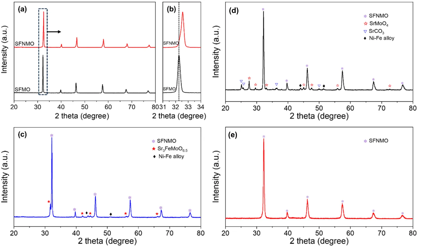
a presents comparative X-ray diffraction (XRD) patterns of SFMO and SFNMO. Analysis confirms that SFNMO perovskite synthesized via high-temperature calcination in air exhibits a phase-pure cubic structure, indicating successful incorporation of Ni
2+ ions into the SFMO lattice. Local magnification of the 31–34° region reveals a slight high-angle shift of SFNMO’s primary peak relative to SFMO (
b). This shift is attributed to Ni
2+ substitution for Fe
2+, where the smaller ionic radius of Ni
2+ (0.72 Å) versus Fe
2+ (0.76 Å) induces minor lattice contraction without altering crystal symmetry [
33]. Based on the Rietveld refinement method, the calculated lattice parameter of SFNMO perovskite is 7.79 Å, which is slightly smaller than that of SFMO perovskite (7.84 Å).
c examines SFNMO’s phase evolution under reducing conditions. While the cubic perovskite framework persists, the emergence of Ruddlesden-Popper (RP)-type phases indicates partial structural reorganization. Concurrently, a weak reflection at 43.8° corresponds to metallic Ni-Fe alloy formation, confirming nanoparticle exsolution accompanied by partial matrix decomposition. To evaluate operational stability, reduced SFNMO was exposed to dry or wet methane (700 °C, 2 h). XRD analysis shows dry methane exposure degrades structural integrity, generating SrCO
3 and SrMoO
4 impurities (
d). Conversely, humidified methane preserves phase purity, with no secondary phases detectable (
e), demonstrating steam’s stabilizing effect. Consequently, all subsequent electrochemical evaluations employed humidified methane fuel.
. (<strong>a</strong>) XRD pattern of the as-synthesized SFMO and SFNMO perovskites; (<strong>b</strong>) Magnified view (31–34° 2θ) highlighting peak shift; (<strong>c</strong>) XRD pattern of SFNMO after reduction at 800 °C in hydrogen for 2 h; (<strong>d</strong>) XRD pattern of the SFNMO perovskite sequentially treated in H<sub>2</sub> for 2 h and then in dry CH<sub>4</sub> for 2 h at 700 °C; (<strong>e</strong>) XRD pattern of the SFNMO perovskite sequentially treated in H<sub>2</sub> for 2 h and then in wet CH<sub>4</sub> for 2 h at 700 °C.
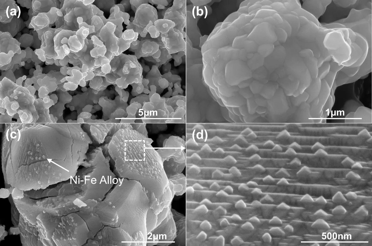
SFNMO perovskite powders were analyzed using FE-SEM before and after reduction to investigate morphological evolution during exsolution.
a,b present the SEM images of the as-synthesized SFNMO at different magnifications, revealing relatively smooth surfaces without detectable impurities. Following reduction treatment at 800 °C for 2 h, distinct morphological evolution occurs as shown in
c. Numerous particles emerge preferentially at crystallographic discontinuities (e.g., grain boundaries or defect sites), while featureless planar regions remain largely particle-free. The exsolved particles exhibit distinctive pyramidal morphologies with dimensions typically exceeding 100 nm. This heterogeneous spatial distribution suggests localized reduction kinetics: regions with enhanced surface energy facilitate preferential nickel exsolution. Similar findings have been reported in previous studies [
25,
28]. This accelerated exsolution triggers localized perovskite decomposition, resulting in phase separation and formation of layered structural domains adjacent to the exsolved particles, which is consistent with XRD-identified RP-type phase evolution.
. FE-SEM images of SFNMO perovskite: (<strong>a</strong>) low-magnification view of the as-synthesized material; (<strong>b</strong>) high-magnification view of the as-synthesized material; (<strong>c</strong>) after reduction at 800 °C for 2 h; (<strong>d</strong>) close-up view after reduction at 800 °C for 2 h.
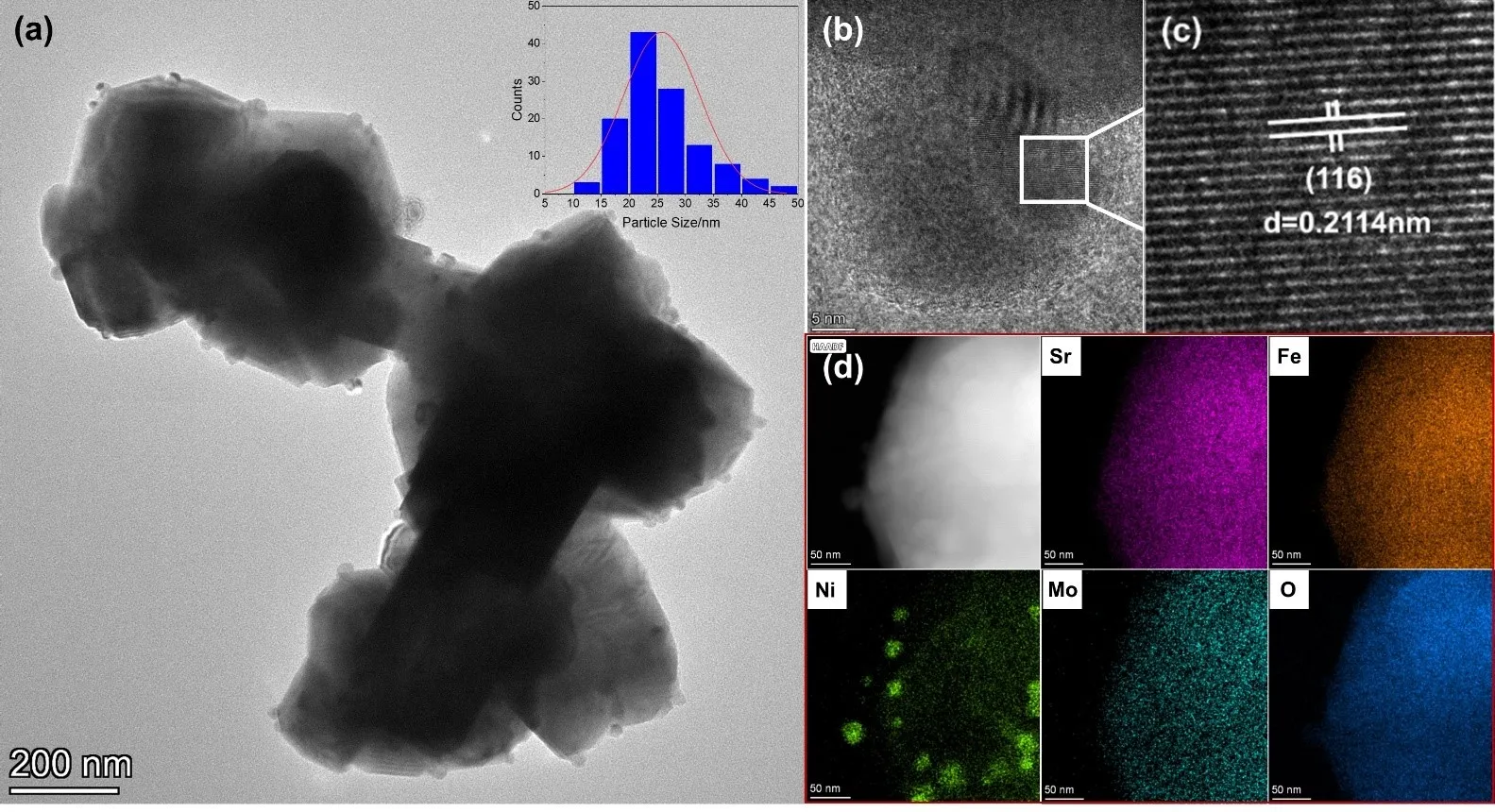
a shows TEM image of the SFNMO perovskite after reduction in a dilute hydrogen atmosphere at 800 °C for 2 h. The image reveals
in-situ exsolved nanoalloy particles on the perovskite surface, displaying a relatively uniform distribution with an average particle size of approximately 27.6 nm and anchored within the matrix. This uniform particle size distribution suggests that the dilute hydrogen atmosphere facilitates the
in-situ exsolution of small and well-dispersed nanoparticles. For a more detailed analysis of the
in-situ exsolution behavior of the SFNMO perovskite, higher-magnification TEM images of the interface between
in-situ exsolved particles and the matrix are presented in
b,c. Lattice fringe analysis of this region yielded a spacing of 0.2114 nm, corresponding to the (116) plane of the RP-phase perovskite. To investigate the compositional differences between the matrix and the
in-situ exsolved particles, EDS mapping was performed on a localized region (
d). The results demonstrate a uniform distribution of strontium (Sr), iron (Fe), molybdenum (Mo), and oxygen (O) throughout the perovskite matrix. In contrast, nickel (Ni) is predominantly concentrated within the
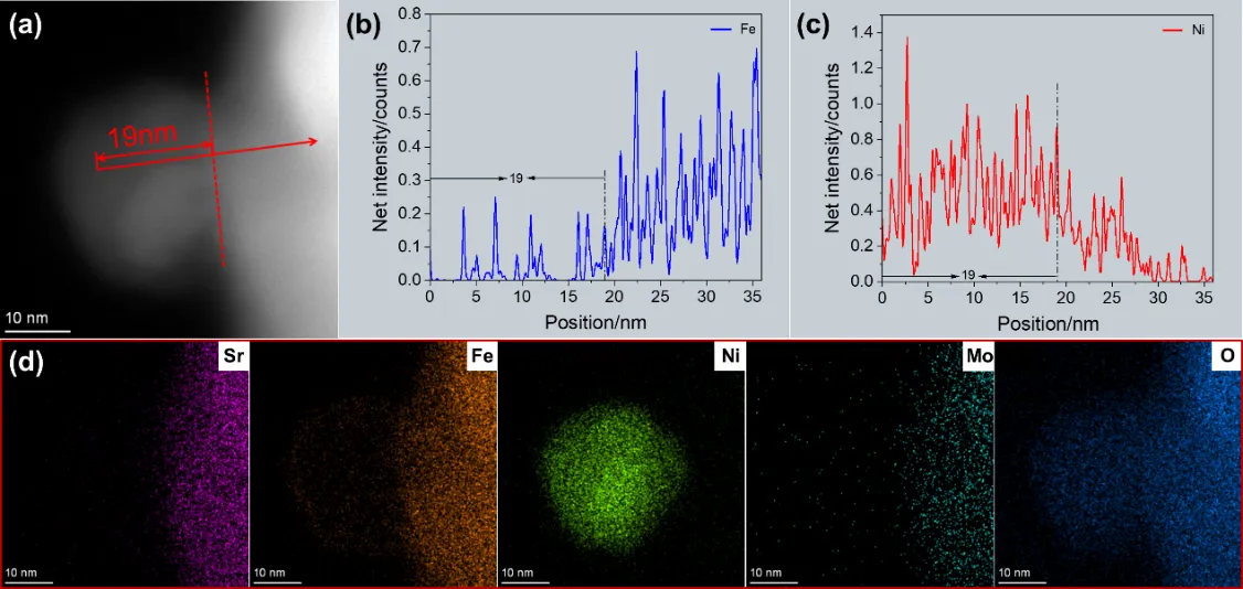
in-situ exsolved particles, with only a minor fraction remaining relatively uniformly distributed in the matrix. Further compositional analysis of the particles and their exsolution characteristics was conducted via EDS line scanning along a trajectory connecting the particles and the matrix (Figures 4a). The line scan profiles for Ni and Fe are presented in Figures 4b and Figures 4c, respectively. The data indicate that the Ni intensity is significantly elevated within the initial 19 nm segment of the scan path, corresponding to the alloy particles. Beyond this 19 nm point, the Ni intensity does not abruptly decrease but rather diminishes gradually with increasing scan distance. This gradual compositional transition suggests that the particles are not fully detached from the host structure but remain partially embedded within the matrix. Conversely, the Fe concentration within the 19 nm segment is relatively low, and beyond this range, it gradually increases with scan distance. This observation suggests that the
in-situ exsolved alloy particles contain not only a substantial amount of Ni but also a minor quantity of Fe. This is corroborated by the EDS mapping of individual particles presented in
d, confirming that the
in-situ exsolved particles are composed of a Ni-Fe alloy.
. (<strong>a</strong>) TEM image of the SFNMO perovskite after reduction in a dilute hydrogen atmosphere (25%H<sub>2</sub>/N<sub>2</sub>) at 800 °C for 2 h; (<strong>b</strong>) High-resolution TEM images of the interface between <em>in-situ</em> exsolved particles and the matrix; (<strong>c</strong>) Lattice fringe analysis of the interface between <em>in-situ</em> exsolved particles and the matrix; (<strong>d</strong>) EDS mapping of localized regions. The histogram in (<strong>a</strong>) shows the size distribution of nanoparticles exsolved on the SFNMO perovskite surface.
. (<strong>a</strong>) HAADF image of SFNMO perovskite after reduction in a dilute hydrogen atmosphere (25%H<sub>2</sub>/N<sub>2</sub>) at 800 °C for 2 h; (<strong>b</strong>) Line-scan results of elemental Fe; (<strong>c</strong>) Line-scan results of elemental Ni; (<strong>d</strong>) EDS mapping results of the associated elements of the <em>in-situ</em> exsolved particles.
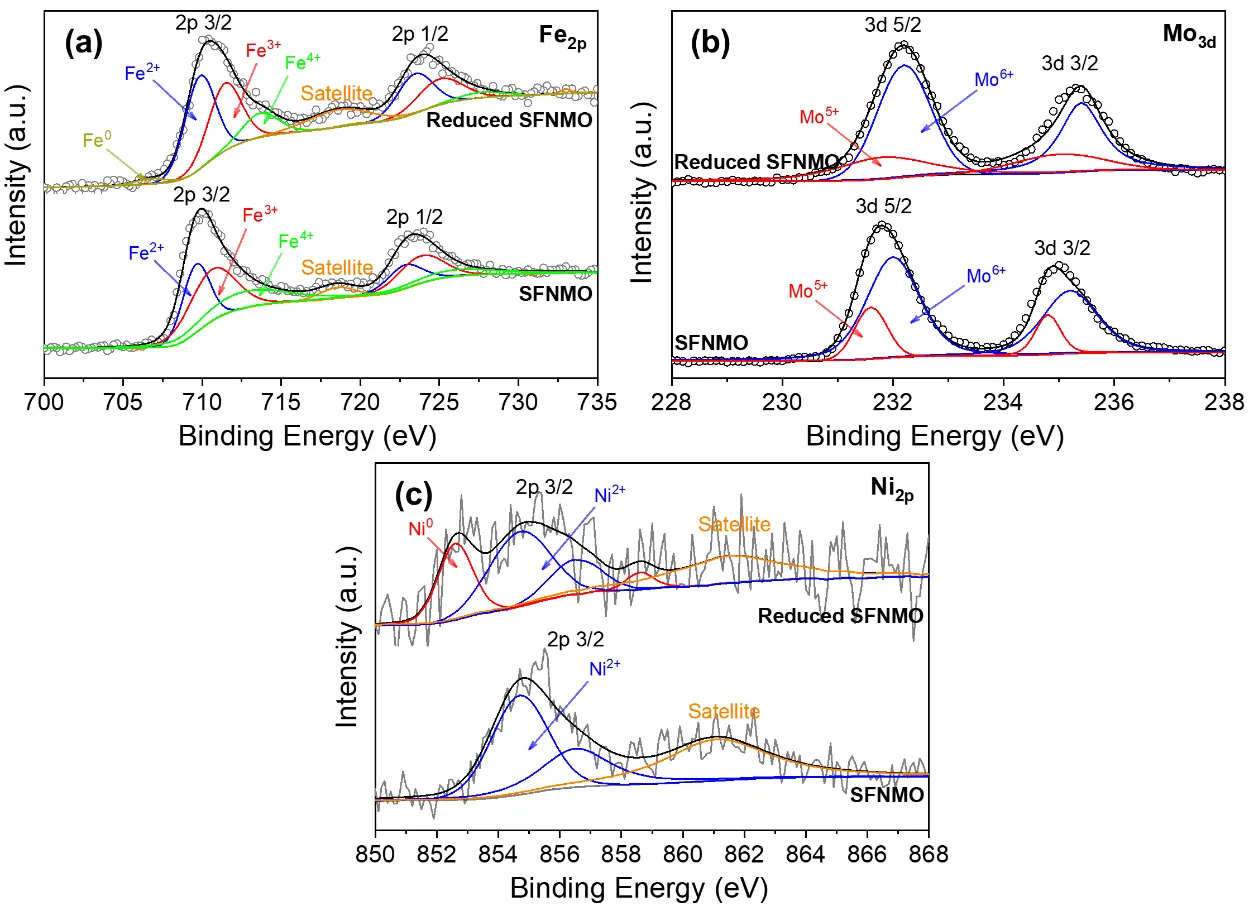
XPS analysis was performed to probe the evolution of elemental composition and valence states in SFNMO perovskite before and after reduction. As shown in
a, the deconvoluted Fe 2p
3/2 spectrum of pristine SFNMO exhibits three characteristic peaks at binding energies of 709.6 eV, 710.6 eV, and 712.7 eV, corresponding to Fe
2+, Fe
3+, and Fe
4+ species, respectively [
34,
35,
36,
37,
38]. Quantitative analysis yields relative proportions of 30.53% Fe
2+, 41.68% Fe
3+, and 27.79% Fe
4+, corresponding to an average iron valence state of +2.97. After reduction, an additional peak emerges at 706.5 eV, attributable to metallic Fe
0 [
39]. However, its low spectral weight (<2%) indicates limited reduction extent. Concurrently, the relative contents shift to 35.40% Fe
2+, 34.69% Fe
3+, and 27.19% Fe
4+, resulting in a reduced average valence state of +2.84. The Mo 3d
5/2 spectra (
b) reveal two oxidation states for both samples: Mo
5+ (231.6 eV) and Mo
6+ (232.0 eV) [
40,
41,
42]. The pristine material shows a Mo
5+/Mo
6+ ratio of 21.48%:78.52% with an average valence of +5.79. This ratio shifts to 29.01%:70.99% (+5.71) post-reduction, confirming partial reduction of molybdenum. Critical evidence is provided by Ni 2p
3/2 analysis (
c). While only signatures of Ni
2+ (854.7 eV and 856.5 eV) are observed in the pristine sample, the reduced specimen displays new peaks at 852.6 eV (Ni
0) and 858.6 eV (Ni
0 satellite) [
39], diagnostic of metallic nickel formation. Combined with the detection of Fe
0, these results demonstrate
in-situ exsolution of Fe-Ni alloy nanoparticles during reductive treatment, establishing SFNMO as a self-exsolving perovskite matrix capable of generating catalytically active heterostructured interfaces.
. XPS spectra of Fe 2p (<strong>a</strong>), Mo 3d (<strong>b</strong>) and Ni 2p (<strong>c</strong>) for the as-synthesized SFNMO and reduced SFNMO perovskites. The gray lines and circles represent the measured raw XPS data.
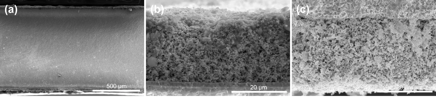
displays the cross-sectional morphology of the symmetrical SFNMO/GDC/SFNMO cell. The micrograph reveals a tri-layer structure comprising two porous electrodes sandwiching a dense electrolyte layer, with both electrodes exhibiting intimate interfacial contact with the electrolyte. The electrode thickness is approximately 30 μm, featuring a porous microstructure conducive to gas diffusion. Conversely, the electrolyte layer measures approximately 660 μm in thickness; its fully dense microstructure effectively prevents gas crossover between fuel and air compartments. These structural characteristics indicate successful fabrication of the LSGM electrolyte-supported cell.
. Cross-sectional SEM image of the whole cell (<b>a</b>), anode (<b>b</b>), and cathode (c) of the symmetrical SFNMO/GDC/SFNMO cell.
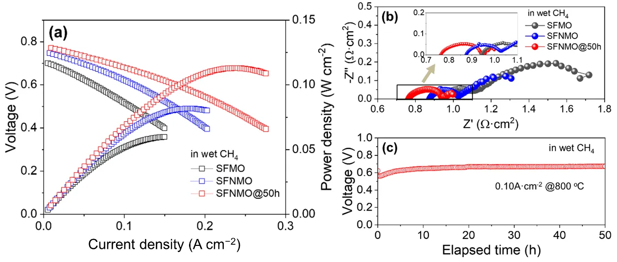
a compares the electrochemical performance of SFNMO/GDC/SFNMO and SFMO/GDC/SFMO symmetrical cells, operating under wet methane at 800 °C. Both cells exhibited open-circuit voltages (OCVs) between 0.7 and 0.8 V. The depressed OCV values primarily stem from the electronic conductivity of GDC electrolytes under intermediate-temperature reducing conditions, resulting from partial reduction of Ce
4+ to Ce
3+ in low oxygen partial environments [
43]. Notably, the SFNMO/GDC/SFNMO cell achieved a peak power density of 82 mW cm
−2, surpassing the 61 mW cm
−2 attained by the SFMO/GDC/SFMO cell. As established in prior analyses, this enhancement is attributed to the
in-situ exsolution of abundant Ni-Fe alloy nanoparticles on the SFNMO anode surface under reducing conditions. The performance enhancement mechanism of the
in-situ exsolved nano-alloy particles on the SFNMO anode is illustrated in
. It is widely recognized that methane conversion on SOFC anodes involves complex chemical and electrochemical processes. The reaction typically begins with methane adsorption and activation on the anode surface, followed by reforming reactions (steam reforming or dry reforming) and subsequent electrochemical oxidation of the resulting syngas (primarily H
2 and CO). For SFMO anodes, methane conversion is relatively slow due to the limited adsorption and dissociation of methane on the surface (
a), which has been identified as the rate-limiting step [
21]. In contrast, for SFNMO anodes, the
in-situ exsolved Ni-Fe nano-alloy catalysts can significantly enhance both the adsorption and catalytic conversion of methane (
b). On one hand, the Ni-Fe nanoparticles efficiently promote methane cracking and reforming reactions, leading to increased production of H
2 and CO. On the other hand, they also serve as highly active sites for the electrochemical oxidation of H
2, CO, and intermediate carbon species (CH
x). Furthermore, the reduced SFNMO anode exhibits an increased oxygen vacancy concentration, providing enhanced pathways for oxygen ion transport. These combined effects synergistically improve the electrochemical performance.
b presents the electrochemical impedance spectra acquired under OCV conditions at 800 °C. The total cell resistance comprises two distinct components: the ohmic resistance (R
o), primarily determined by the ionic conductivity of the electrolyte and electrodes, and the polarization resistance (R
p), associated with electrode reaction kinetics and gas diffusion processes. The SFNMO cell exhibited an R
o of 0.88 Ω cm
2, marginally lower than the 0.94 Ω cm
2 observed for the SFMO cell, potentially due to the enhanced conductivity of SFNMO perovskite compared to the SFMO perovskite [
33]. Crucially, the predominant performance difference stems from a significant reduction in R
p, which serves as the key determinant of the performance disparity. This reduction indicates lower activation energy requirements for electrochemical reactions during methane-fueled operation, thus confirming that the
in-situ exsolution of Ni-Fe nanoalloy particles effectively enhances the catalytic conversion efficiency of methane on the perovskite anode.
To evaluate the operational stability of the SFNMO-based cell under methane, a constant-current test was conducted at 0.1 A cm
−2 (
c). The cell voltage initially decreased rapidly, subsequently increased gradually, and stabilized at approximately 0.67 V without degradation, demonstrating robust stability in wet methane. Post-stability testing revealed the peak power density increased from 82 to 113 mW cm
−2 (Figures 7a). Impedance analysis indicated a slight reduction in R
o from 0.88 to 0.76 Ω cm
2, likely due to improved electrode-electrolyte interfacial contact during polarization. More significantly, a pronounced decrease in R
p was observed, suggesting electrochemical activation-induced microstructural optimization of the electrode.
. (<strong>a</strong>) Cell performance of SFNMO/GDC/SFNMO and SFMO/GDC/SFMO symmetrical cells before and after constant-current discharging under wet methane at 800 °C for 50 h; (<strong>b</strong>) The corresponding EIS spectra; (<strong>c</strong>) Constant-current stability of the SFNMO/GDC/SFNMO cell under wet methane at 800 °C.
. The catalytic conversion mechanism of methane on SFMO (<b>a</b>) and SFNMO (<b>b</b>) anodes. The gray arrow represents the surface reaction process, the green arrow represents the electron transfer process, and the purple arrow represents the oxygen ion transport process.
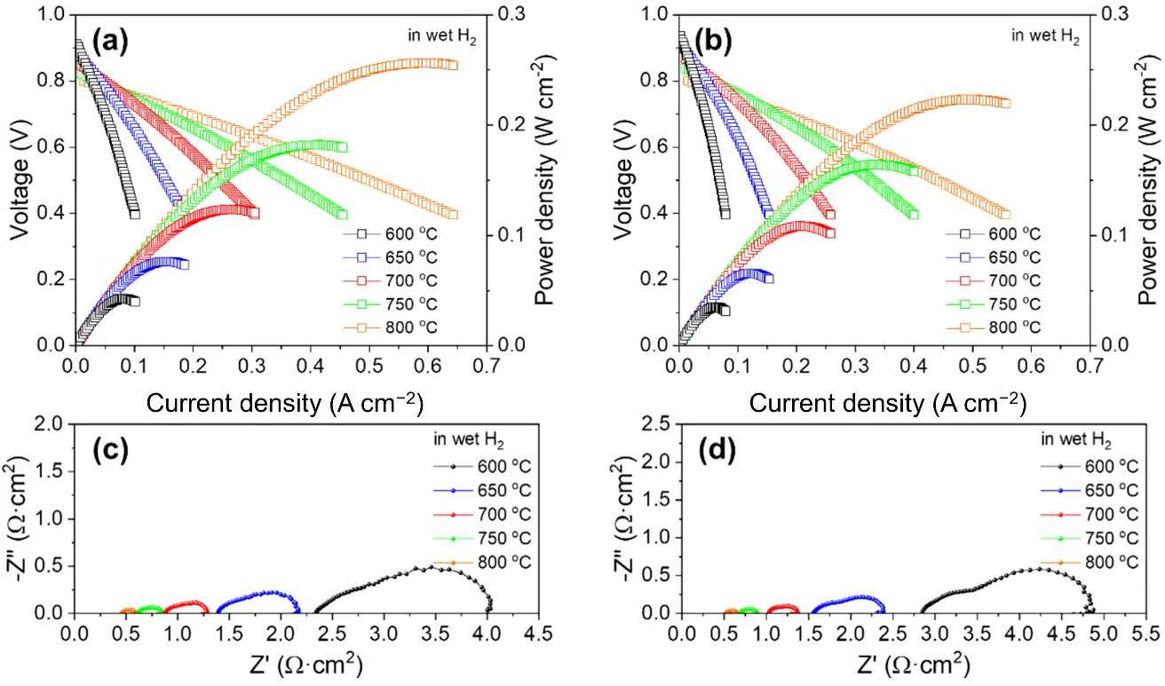
Although methane-fueled performance was enhanced, hydrogen-fed operation exhibited compromised performance. The temperature-dependent electrochemical performance of SFMO/GDC/SFMO and SFNMO/GDC/SFNMO symmetrical cells are displayed in
a and
b, respectively. Both cells exhibited OCVs between 0.80 and 0.94 V across all temperatures—significantly lower than cells employing YSZ or LSGM electrolytes. Notably, while OCV decreased with increasing temperature, power density increased monotonically. The SFMO anode cell achieved peak power densities of 43, 77, 124, 182, and 256 mW cm
−2 at 600, 650, 700, 750, and 800 °C, respectively. Under identical conditions, the SFNMO anode cell yielded corresponding values of 35, 66, 109, 164, and 223 mW cm
−2, demonstrating the consistently superior performance of SFMO anodes in wet hydrogen. This performance degradation in SFNMO originates from structural alterations during reduction:
In-situ exsolution of Ni-Fe nano-alloy particles induces partial perovskite decomposition, forming secondary RP phase impurities. This phase segregation reduces available electrochemically active sites and compromises interfacial ion transport efficiency. Although the
in-situ exsolved Ni-Fe alloys enhance hydrogen cracking kinetics, this catalytic benefit is offset by the degraded structural integrity of the SFNMO matrix. This structural compromise is further evidenced by EIS spectra, that the polarization resistance of the SFNMO/GDC/SFNMO symmetrical cell (Figures 9d) is substantially higher than that of the SFMO/GDC/SFMO symmetrical cell (Figures 9c) at each equivalent temperature. These findings underscore the critical importance of preserving matrix structural integrity during
in-situ exsolution of metallic nanoparticles, which is potentially achievable through reduced reaction temperatures or optimized doping concentrations.
. (<strong>a</strong>) Cell performance of the SFMO/GDC/SFMO symmetrical cell under wet hydrogen at 600–800 °C; (<strong>b</strong>) Cell performance of the SFNMO/GDC/SFNMO symmetrical cell under wet hydrogen at 600–800 °C; (<strong>c</strong>) EIS spectra of the SFMO/GDC/SFMO symmetrical cell under wet hydrogen at 600–800 °C; (<strong>d</strong>) EIS spectra of the SFNMO/GDC/SFNMO symmetrical cell under wet hydrogen at 600–800 °C.
The authors express gratitude to the fund of National Natural Science Foundation of China (Grant No. 52302281), Shandong Provincial Natural Science Foundation (Grant No. ZR2022MB060), and Qingdao Natural Science Foundation (Grant No. 23-2-1-225-zyyd-jch) for providing financial support for this study.
Conceptualization, Z.H.; Methodology, H.D.; Formal Analysis, H.D. and S.J.; Investigation, H.D. and S.J.; Writing—Original Draft Preparation, H.D.; Writing—Review & Editing, Z.H.; Visualization, H.D.; Supervision, Z.H.; Funding Acquisition, Z.H.
Not applicable.
Not applicable.
Data will be made available on request.
This research was funded by the National Natural Science Foundation of China (Grant No. 52302281), Shandong Provincial Natural Science Foundation (Grant No. ZR2022MB060), and Qingdao Natural Science Foundation (Grant No. 23-2-1-225-zyyd-jch).
The authors declare that they have no known competing financial interests or personal relationships that could have appeared to influence the work reported in this paper.