1. Introduction
1.1. Research Background
The advent of the Industry 4.0 era has accelerated the transformation of the manufacturing industry into intelligent manufacturing [
1,
2,
3]. At its core, intelligent manufacturing integrates new-generation information technology with advanced manufacturing techniques, fostering innovation in manufacturing paradigms through the digital integration and optimization of the entire product lifecycle (design, manufacturing, service) [
4,
5]. Intelligent production lines, as the key enabler of intelligent manufacturing, are transitioning from traditional automation models (such as the Ford assembly line) to modern “lighthouse factory” models. This transformation is largely driven by breakthroughs in key technologies, including but not limited to six-axis collaborative robots [
6], deep learning algorithms [
7], digital twin systems [
8,
9], industrial Internet of Things (IIoT) [
10], cloud service platforms [
11], cyber-physical systems (CPS) [
12], blockchain edge computing architectures [
13], big data analytics [
14], and artificial intelligence decision-making systems [
15,
16]. Through their coordinated development, these technologies collectively empower autonomous perception, intelligent scheduling, and dynamic decision-making capabilities within the production system. From a systems theory perspective, intelligent manufacturing systems can be modeled as distributed networks of multiple intelligent agents. Each node adds value by coupling material, energy, and information flows. Typical applications include intelligent robots equipped with industrial vision, achieving μm-level precision control in assembly, welding, and inspection processes via deep learning algorithms [
17]. These systems encompass intelligent equipment such as CNC machine tools, robot execution terminals [
18], intelligent logistics systems (conveying/loading), and online detection devices [
19]. A key development is the deployment of wireless sensor networks, based on IIoT and RFID(Radio Frequency Identification technology) technologies, in discrete manufacturing workshops [
20], enabling real-time data collection on the production floor [
21]. When combined with cloud-based data mining and knowledge discovery technologies [
22,
23], this system supports multi-dimensional perception and dynamic optimization of production processes [
24], full-chain traceability of product quality [
25], and predictive maintenance of equipment [
26]. Research has shown that hybrid optimization strategies, such as combining backpropagation neural networks (BPNN) with genetic algorithms (GA), significantly improve the adaptive adjustment of process parameters [
27].
Digital twin technology has become a critical tool for configuring and optimizing intelligent manufacturing systems, with successful applications in fields such as glass manufacturing [
28], ship pipeline production [
29], automotive parts manufacturing [
30], stepper motor assembly [
31], and plastic injection molding (PIM) [
32]. The adaptability and effectiveness of digital twin technology in various manufacturing scenarios have been validated. Current research in both academic and industrial sectors is evolving from isolated technological breakthroughs to system-level intelligent collaboration. For example, the intelligent manufacturing framework based on multi-agent systems and reinforcement learning, developed by Kim et al. [
33], has achieved breakthroughs in three areas: autonomous machine decision-making, system-level social interaction, and dynamic environmental learning mechanisms. This architecture enables manufacturing systems to adapt to complex changes in the production environment.
In response to increasing task demands in industrial production, Yin et al. [
34] integrated a job priority mechanism within a cloud-edge computing framework. By combining Particle Swarm Optimization (PSO) and Gravitational Search Algorithm (GSA), they achieved notable improvements in task scheduling optimization, particularly in key performance indicators such as real-time task completion rates. Similarly, the heterogeneous Demand-Capacity Synchronization (HDCS) method proposed by Ling et al. [
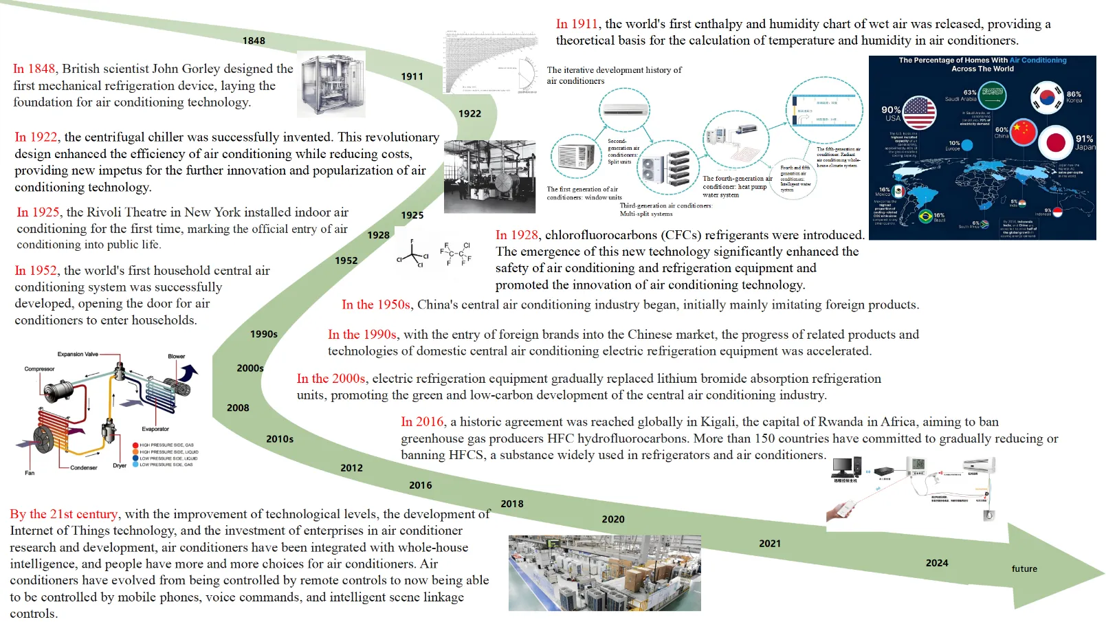
35] represents a new direction for optimizing intelligent production lines. This method integrates AI and IIoT technologies, using computer vision for real-time capacity analysis of assembly units. It constructs an intelligent decision-making closed loop, supporting millisecond-level information sharing, and improving the coordination and scheduling efficiency of assembly lines (ACL). illustrates the historical evolution and development of air conditioners. Understanding this development is essential for grasping the transition toward digitalization and intelligence in air conditioning design.
. The development history of air conditioners.
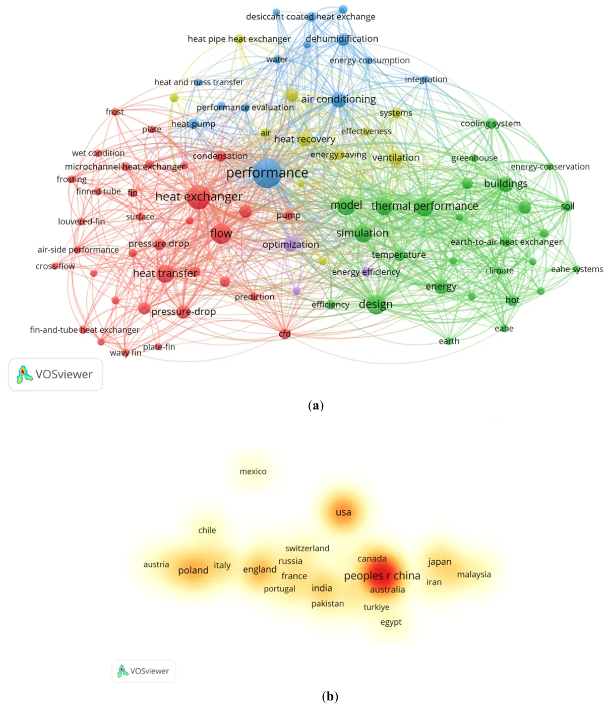
A search was conducted in the Web of Science Core Collection database, covering the period from 1993 to 2025, with the search date set as 2 June 2025. The search query used was TS = (“Intelligent Manufacturing” or “Smart Manufacturing”) and (“Production Line” or “Manufacturing System”). The literature analysis chart based on the search results is shown in . After screening, a total of 829 articles meeting the criteria were identified. Over the years, the increasing number of publications highlights the growing interest in intelligent production lines and manufacturing systems. Through literature review and cluster analysis, eight main research hotspots were identified: #0 Intelligent Manufacturing System, #1 Anomaly Detection, #2 Industry 4.0, #3 Cloud Computing, #4 Intelligent Manufacturing System (appearing twice), #5 Digital Twin, #6 Intelligent Manufacturing, and #7 Genetic Algorithm. The primary research fields include engineering, computer science, operations research and management science, automatic control systems, telecommunications, materials science, and robotics. China, the United States, and South Korea are the top three countries contributing the most research in this area. Key journals for publishing related articles include the Journal of Manufacturing Systems, the International Journal of Advanced Manufacturing Technology, Manufacturing Technology, IEEE Access, the Journal of Intelligent Manufacturing, and Robotics and Computer-Integrated Manufacturing.
. Literature data analysis. (<b>a</b>) keyword search situation. (<b>b</b>) National search situation.
While the intelligent transformation of central air conditioning heat exchanger production lines has led to technological advancements and applications, there is limited research on the transformation of air conditioning heat exchanger production lines. This article aims to provide a detailed exploration of this topic, focusing on aspects such as the current state of intelligent manufacturing, the research objectives for intelligent production lines of air conditioning heat exchangers, overall architecture, key system design, intelligent operation and maintenance plans, core function realization, and the impact of intelligent manufacturing on air conditioning heat exchangers. By analyzing the structural composition of air conditioning heat exchangers, we propose the layout and technological processes for an intelligent production line. The integration and collaboration mechanisms between the intelligent production line and intelligent operation and maintenance are also examined. A case study of the intelligent production line for air conditioning heat exchangers is presented, highlighting the importance of reasonable layout and efficient operation. The goal is to propose a comprehensive set of construction plans for intelligent production lines for heat exchangers and implementation strategies for intelligent operation and maintenance in the existing air conditioning manufacturing industry.
2. Design Scheme
2.1. Traditional Production Line
The traditional production process for multi-split central air conditioning heat exchangers consists of four steps. First, a punch press forms aluminum sheets from rolled stock. Second, copper tubes are manually inserted into the holes of the aluminum sheets. Third, the heat exchanger is manually transported to a tube expansion machine for expansion. Finally, U-tubes are manually inserted, and the connections are welded. This production method follows a typical discrete manufacturing model. In traditional production lines, the transfer of workpieces between processes relies on the staged accumulation of semi-finished products. Once the semi-finished products in a specific area reach a preset quantity threshold, forklifts perform centralized transfers [
36].
2.2. The Layout of the Production Line
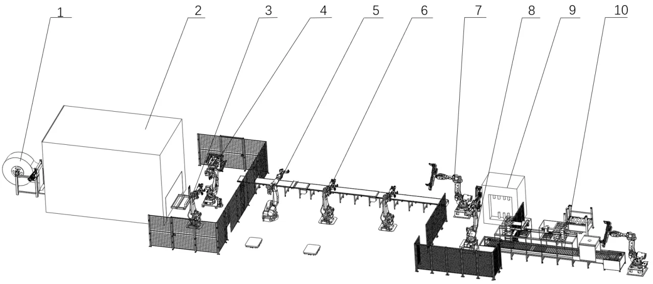
To address the issues in the traditional processing production line, the intelligent manufacturing production line for multi-split central air conditioning heat exchangers has been optimized [
37]. As illustrated in , the design of this optimized production line includes the following key systems:
- 1.
-
Blanking Machine Feeding System: This system is responsible for unrolling aluminum coil raw materials, blanking the material, inserting steel needles for positioning, and unloading.
- 2.
-
End Plate Installation System: This system installs the end plates on both sides of the heat exchanger.
- 3.
-
Tube Insertion System: In this system, bent copper tubes are inserted into the punched holes of the heat exchanger.
- 4.
-
Tube Expansion System: This system expands the walls of the copper tubes, reducing the distance between the punched holes in the aluminum sheet.
- 5.
-
Drying System: The drying system removes oily substances inside the heat exchanger to minimize oil evaporation.
- 6.
-
Welding System: This system ensures that the U-bent pipe is securely welded to the copper tube.
- 7.
-
Intelligent Monitoring System: The monitoring system oversees the entire production line, triggering timely alarms in case of any operational issues.
All process areas in this intelligent production line are connected by conveyor belts for efficient transportation [
38].
. Intelligent manufacturing line of multi-split central air conditioning heat exchanger. 1. Unfolding device, 2. Punching machine room, 3. Positioning the steel needle robot, 4. Punching machine feeding robot, 5. End plate robot, 6. Plug pipe robot, 7. Tube expanding machine online robot, 8. Drying online robot, 9. Tube expanding machine, 10. Drying machine.
The action process of the intelligent manufacturing production line of the multi-split central air conditioning heat exchanger is as follows:
- 1.
-
Uncoiling and Punching Process: The aluminum coil is uncoiled by the uncoiling device and connected to the feeding end of the punching machine. The punching machine then shapes the aluminum sheet using the die, after which it falls into the cutting device. Once the punching is complete, the punching machine pushes the sheet into the cutting device, and the robotic arm inserts a positioning steel needle. The cutting robot holds the needle and places the heat exchanger on the conveyor belt, completing the punching and cutting process.
- 2.
-
End Plate Installation: Once the punch press process is finished, the end plate installation robot installs the raw end plates on both sides of the heat exchanger. This is done after the heat exchanger is transported and positioned by the conveyor belt. Once the end plates are installed, the pipe insertion robot inserts the bent copper tube into the punched holes of the aluminum sheet in two separate stations.
- 3.
-
Tube Expansion: The offline robot moves the heat exchanger to the tube expansion station after the tube insertion process. The tube expansion machine then expands the copper tube inside the heat exchanger. The tube expansion station can rotate 360°, and the tube expansion process is completed after a certain period.
- 4.
-
Drying Process: Once the tube expansion process is finished, the tube expansion station rotates 90°. The dryer online robot removes the heat exchanger from the tube expansion station and places it on the dryer conveyor belt. The dryer offline robot rotates 90° and positions the heat exchanger for drying.
- 5.
-
Conveyor Belt and Drying: The dryer conveyor belt transports the heat exchanger into the dryer. Once the drying is completed, the conveyor belt moves the heat exchanger out of the dryer. The dryer’s offline robot then picks up the dried heat exchanger from the conveyor belt and places it onto the conveyor belt of the automatic welding machine.
2.3. Production Line Management System
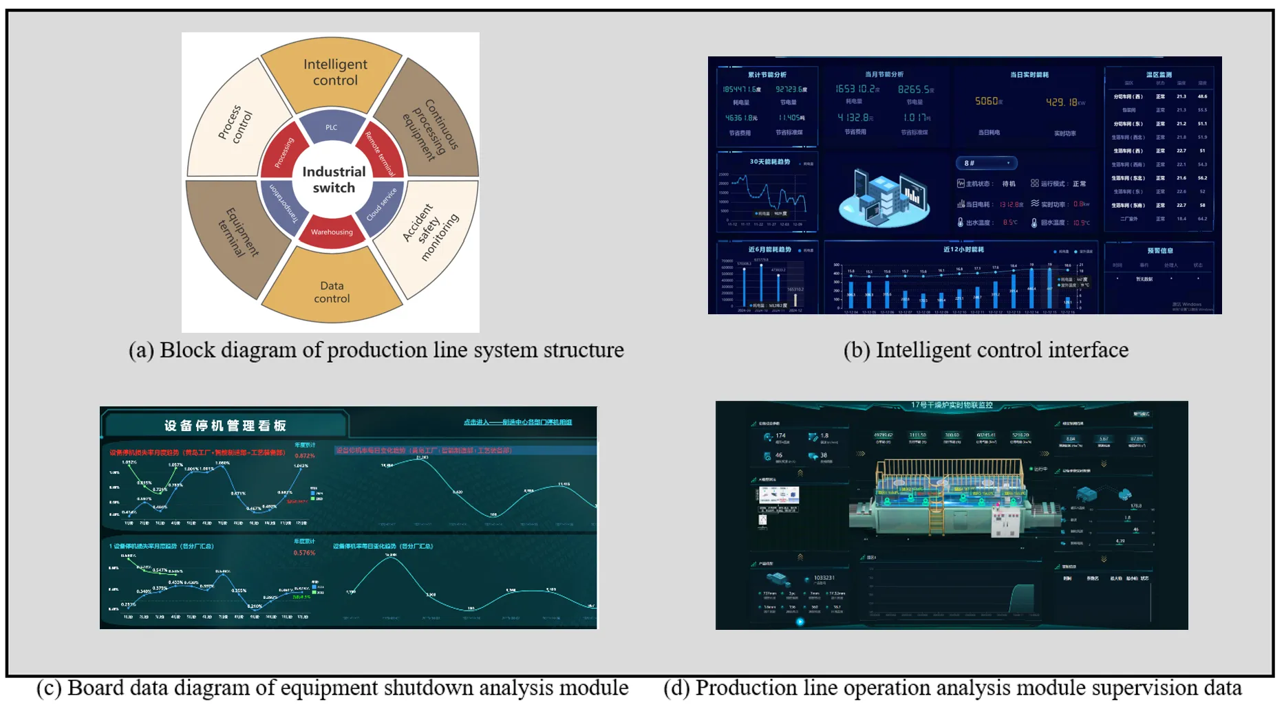
The intelligent upgrade of the heat exchanger production process for multi-split central air conditioning systems involves not only modernizing the production equipment but also establishing a comprehensive intelligent monitoring and management system. This smart manufacturing system adopts an architecture that integrates digital platforms with intelligent equipment. The system’s core components include automated terminal devices for mechanical processing, a Manufacturing Execution System (MES) for data integration and management, a Programmable Logic Controller (PLC) for process control, and a cloud-based remote monitoring service platform. As shown in , the figure illustrates the structural framework and module diagram of the intelligent manufacturing production line system for multi-split central air conditioning heat exchangers [
39].
. Block diagram and module diagram of the intelligent manufacturing production line system for multi-split central air conditioning heat exchanger.
The system incorporates an intelligent management platform based on remote terminals to enable data collection, operational status monitoring, and production information integration on intelligent manufacturing lines. This platform, designed with a modular approach, includes the following core components: a smart control interface, a dashboard for analyzing equipment downtime, a supervision data chart for monitoring production line operations, and a product improvement analysis chart.
3. Design Methodologies
The main hardware system of the production line is essential for ensuring the continuity of on-site production and maintaining product quality. The design of the main hardware system for the intelligent manufacturing production line of multi-split central air conditioning heat exchangers includes the following key aspects.
3.1. Punching Machine Feeding System
The sheet punch machine’s feeding and unloading system comprises a feeding device, a sheet punch machine and a group of fin unloading devices. The group of fin unloading devices includes a fin storage and retrieval equipment, and a positioning steel needle robot.
The raw aluminum coil is placed on the uncoiling device, with its end connected to the feeding end of the punching machine. Inside the punching machine, the aluminum sheet is punched. After being punched, the sheet falls onto the storage and retrieval device. Once a certain number of punches are completed, the storage and retrieval device slides out of the protective room outside the punching machine. The positioning steel needle robot then inserts the steel needle. Following this, the robot from the punching machine places the heat exchanger onto the conveyor belt.
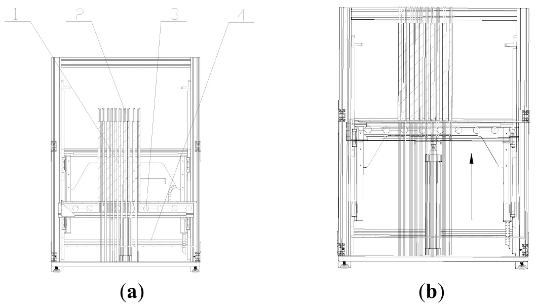
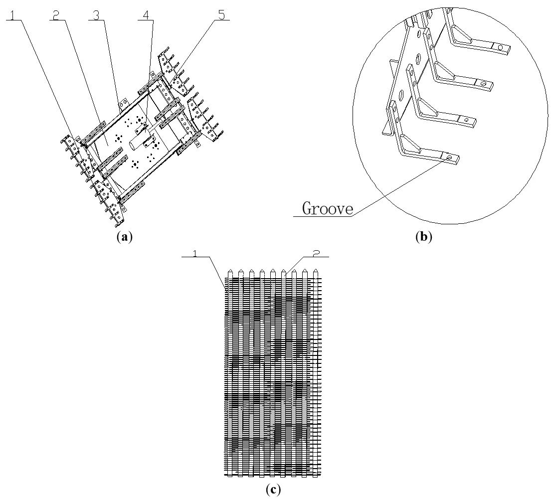
The fin access device comprises an access bracket, a support base plate, a lifting support plate, and an offline robot. The access bracket is a frame structure within which a storage position is formed. The support base plate is horizontally placed on the access bracket at the bottom of the storage position. As shown in , the support base plate is equipped with a vertically positioned drop pin. The bottom of the drop pin is fixed to the support base plate, while its top extends vertically upward, positioning the fins after they are processed and dropped into the storage position.
After being stamped by the punching machine, the aluminum sheets fall onto the lifting support plate of the positioning steel needle guiding device. At this point, the heat exchanger contains the drop steel needle, but the punched holes in the aluminum sheet are not filled; some holes remain open for inserting the positioning steel needle. The opening of the lifting support plate is designed to remain closed for the holes that need the positioning steel needle inserted. This ensures that when the lifting support plate is raised, the drop steel needle does not move with it, and the plate does not rise too high, which could otherwise disrupt the alignment of the aluminum sheets. This design ensures that all the aluminum sheet openings, whether in the same column or row, remain concentric, facilitating the precise insertion of the positioning steel needle.
. Working state of the flap access device. (<b>a</b>) Initial position of the lifting support plate of the fin access device. 1. fin, 2. positioning steel needle, 3. lifting support plate, 4. bottom plate. (<b>b</b>) Upward position of the lifting support plate of the fin access device.
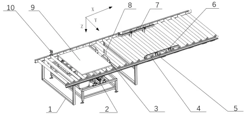
The end plate installation system consists of an end plate robot, a fin conveying line, and its positioning mechanism. The end plate robot picks up the end plates from the raw material area at the rear and, with the assistance of the conveyor belt and its positioning mechanism, installs them on both sides of the heat exchanger. This ensures secure installation, fixing the internal pipes, fins, and other components, which prevents loosening or displacement and guarantees long-term stable operation [
40].
The fin conveying line is equipped with end plate mounting positions, with a stopper located downstream of these positions. The stopper rises above the roller as the fin stack moves along the conveying line to the end plate mounting position. The lifting stopper, installed on the conveying line, rises before the fin stack reaches the end plate mounting position, effectively halting the movement of the fin stack.
As shown in , in terms of the coordinate system, the conveying direction of the fin conveyor line is defined as the X direction, the width direction as the Y direction, and the height direction as the Z direction. The end plate dimensions along the Z direction are equal to its width, and the fin stack dimensions along the Z direction are also equal to its width. The width (L
1) of the end plate is greater than the width (L
2) of the fin stack. The thickness (L
3) of the support plate must satisfy the following condition:
To avoid interference with the roller when the end plate is installed at both ends of the fin stack.
. Heat exchanger fin conveying line. 1. Support frame, 2. Lifting member, 3. Lifting stop, 4. Guide section, 5. Alignment bracket, 6. Center beam, 7. Center component, 8. Roller cylinder, 9. Support plate, 10. Inspection piece.
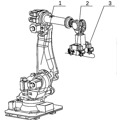
The catheter system equipment includes a catheter insertion robot, as shown in . This robot has a main body and a catheter insertion fixture attached to it. The fixture includes two spaced-apart catheter insertion components. Two catheter insertion robots are positioned along the fin conveyor line and spaced apart to improve the efficiency of tube fitting.
. Tube insertion robot. 1. Tube insertion robot, 2. U-shaped tube component, 3. Tube insertion fixture.
The clamping system consists of a clamping cylinder and two clamping ends. Each clamping end is equipped with a shrink end, and the two clamping ends are set apart. Each clamping end forms a clamping recess, where the pipeline component is securely held in the clamping position created by the two recesses.
3.4. Expansion Pipe System
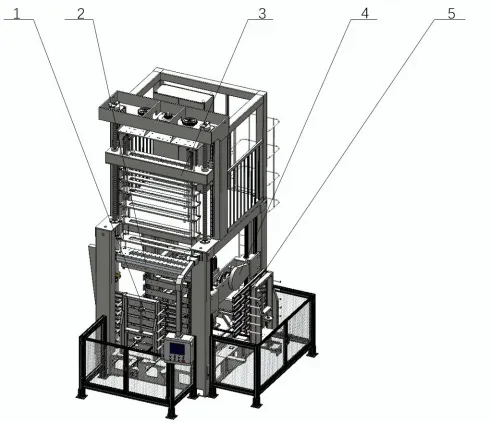
As shown in , the tube expansion system mainly comprises a vertical tube expansion mechanism. The tube expansion machine consists of a tube expansion station and a tube expansion controller. The tube expansion station can rotate 360° to facilitate the placement and removal of heat exchanger fins by the feeding and discharging robot.
The vertical expansion tube equipment features a vertically oriented layout structure. Its core components include the base support, guide columns, hydraulic drive mechanism, power oil station, diameter expansion adjustment unit, workpiece positioning fixture, and electrical control cabinet. The system’s control is automated using a programmable logic controller (PLC), complemented by a human-machine interaction touch interface, ensuring the stability of the processing process and operational safety [
41].
. Bulging tube machine. 1. Automatic door, 2. Clamping claw, 3. Expansion tube position, 4. Flaring mobile mechanism, 5. Rotary table.
As shown in , the drying system primarily consists of a tunnel dryer. During the punching and tube insertion processes, a small amount of oily substance is sprayed onto the fins of the heat exchanger to facilitate the operations. The goal of the drying process is to remove these oily residues to prevent them from volatilizing into the air when the air conditioning system operates, which could lead to environmental pollution and potential health risks. As shown in , this is a tunnel dryer.
. Tunnel dryer. 1. Return air duct, 2. Motor, 3. Air outlet, 4. Heating tube, 5. Cooling room, 6. Drying conveyor belt.
The tunnel dryer consists of a drying conveyor belt, return air ducts, outlets, heating tubes, cooling chambers, and motors. A robot at the top of the dryer places the heat exchanger onto the conveyor belt. The conveyor belt then transports the heat exchanger to the drying heating area, where two heating zones prevent the heat exchanger from accumulating. After the drying process, the heat exchanger is moved to the cooling chamber for cooling. Once cooled, the heat exchanger is removed from the dryer by a robot at the bottom [
42].
4. Analysis of Aluminum Sheet Processing
4.1. Analysis of Fin Forming Process
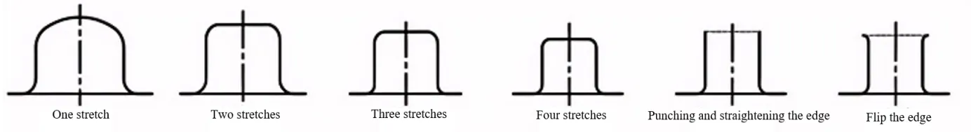
Given the complex structure of the fins and the requirement for mass production, the forming process must involve multiple stages of plastic processing, including continuous drawing, precision punching, and flanging. Traditional single-process molds and composite molds have limitations in processing efficiency and consistency. This study adopts a continuous progressive die scheme with automatic feeding capabilities to overcome these challenges, enabling high-precision and efficient production. illustrates the typical process flow for fin stamping. shows the shapes of the fins after being stamped by different processes.
. Typical stamping process of Air conditioning fins.
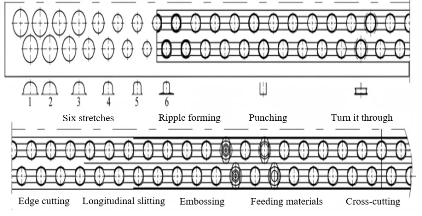
. The layout of the Air conditioning fins forming. The numbers 1 to 6 indicate that the fin has been extended six times.
The deep drawing process, a core stamping step in fin forming, requires a systematic design of parameters based on the product’s structural characteristics. For most fins, continuous deep drawing typically requires more than three cycles. However, the number of processes can be reduced for products with lower hole height requirements (typically less than one-third of the fin diameter). When the target hole diameter is ϕ 78 mm, theoretical calculations suggest that 34 deep drawing cycles are necessary, with the single deep drawing coefficient controlled within the range of 0.8 ± 0.05. Experiments have demonstrated that increasing the number of deep drawing cycles to 5~6 can significantly improve wall thickness uniformity and reduce the risk of cracking. Given the high-flange forming characteristics of thin plate fins, a 6-cycle deep drawing scheme was adopted, and a spherical punch design (with a curvature radius R = 2t, where t is the plate thickness) was used to promote the directional flow of the blank in the die cavity, resulting in a 12~15% increase in flange height. The key forming parameters, including the gap between the convex and concave dies and the fillet radius, were optimized through orthogonal experiments, as shown in [
43].
In the flanging process, the design parameters and gap control of the punch are crucial to achieving high forming quality. Experimental data and theoretical calculations indicate that the flanging punch generates significant tangential tensile stress on the fin material during operation, causing the material thickness to decrease by approximately 15–20%. To ensure optimal forming quality, the flanging gap should be controlled within the range of (0.9~0.95)t0, with a precise gap value of 0.24 mm (where t0 is the initial material thickness). The specific mold dimensions are as follows: the diameter of the flanging punch is ϕ 8.25 ± 0.01mm, and the diameter of the die is ϕ 8.49 ± 0.01mm. This combination ensures uniform material flow and prevents defects such as wrinkling or cracking [
44].
In the design of the heat exchanger fin progressive die, optimizing the sampling scheme is key to ensuring production efficiency and product quality. shows the shape of the air conditioner fins after each process is completed during the fin forming process.
.
Deep drawing convex and concave die forming parameters unit: mm.
| Drawing Number |
Punch Diameter |
Diameter of Punch Ball Head |
Punch Profile Radius |
Die Diameter |
| Parameter 1 |
Parameter 2 |
Parameter 3 |
Parameter 1 |
Parameter 2 |
Parameter 3 |
Parameter 1 |
Parameter 2 |
Parameter 3 |
Parameter 1 |
Parameter
2 |
Parameter
3 |
| 1 |
ϕ 17.5 |
ϕ 17.5 |
ϕ 19 |
ϕ 28 |
ϕ 28 |
ϕ 26 |
ϕ 7 |
ϕ 7 |
ϕ 7 |
ϕ 18.4 |
ϕ 18.8 |
ϕ 19.8 |
| 2 |
ϕ 17.5 |
ϕ 17.5 |
ϕ 19 |
ϕ 28 |
ϕ 28 |
ϕ 26 |
ϕ 7 |
ϕ 7 |
ϕ 7 |
ϕ 18.4 |
ϕ 18.8 |
ϕ 19.8 |
| 3 |
ϕ 14.3 |
ϕ 14.3 |
ϕ 15.2 |
ϕ 30 |
ϕ 30 |
ϕ 28 |
ϕ 5.5 |
ϕ 5.5 |
ϕ 5.5 |
ϕ 15.2 |
ϕ 15.6 |
ϕ 16 |
| 4 |
ϕ 11.8 |
ϕ 11.8 |
ϕ 12.2 |
ϕ 32 |
ϕ 32 |
ϕ 32 |
ϕ 4 |
ϕ 4 |
ϕ 4 |
ϕ 12.7 |
ϕ 13.1 |
ϕ 13.1 |
| 5 |
ϕ 9.8 |
ϕ 9.8 |
ϕ 10 |
ϕ 36 |
ϕ 36 |
ϕ 36 |
ϕ 2.8 |
ϕ 2.8 |
ϕ 2.8 |
ϕ 10.7 |
ϕ 11.1 |
ϕ 11.1 |
| 6 |
ϕ 8.2 |
ϕ 8.2 |
ϕ 7.9 |
ϕ 38 |
ϕ 38 |
ϕ 38 |
ϕ 2 |
ϕ R2 |
ϕ 1.8 |
ϕ 9.1 |
ϕ 9.2 |
ϕ 8.8 |
4.3. Die Design for Tablet Punching Machines
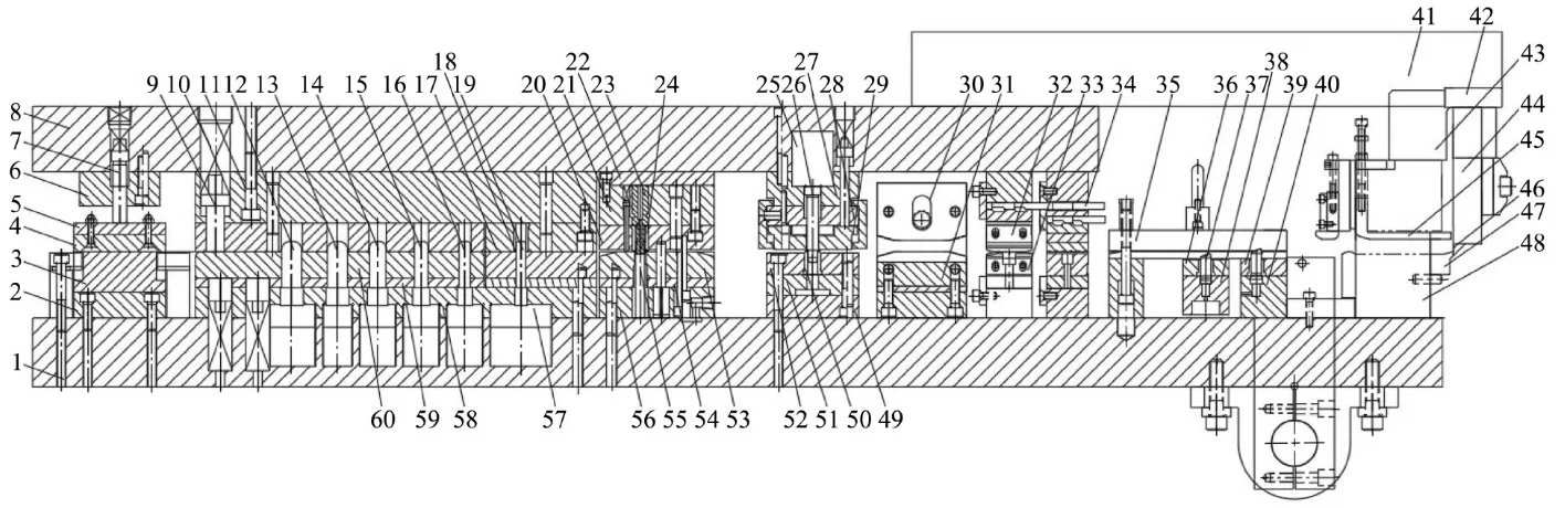
As shown in , the multi-station progressive die is designed with a modular approach, incorporating nine processes: blanking, deep drawing (using a ball head punch with R = 1.5t), precision punching (with a clearance of 8%t), flanging (with a 30° cone angle), double-sided trimming (with a tool edge clearance of 0.05 mm), embossing (with a depth of 0.3 ± 0.02 mm), and cross-cutting. The die features a main structure with dimensions of 1230 mm (L) × 580 mm (W) × 245 mm (closure height). It utilizes a four-guide-post ball die frame (SKF linear bearings, with guidance accuracy of ±0.01 mm) to ensure high motion stability [
45].
. Sectional view of mold structure. 1. Lower die seat, 2. Pressing pad, 3. Guide block, 4. Wool felt, 5. Press plate, 6. Pressing pin fixing plate, 7. Pressing pin, 8. Upper die seat, 9. Press rod, 10. Spring, 11. Pad, 12. Deep drawing punch, 13. Deep drawing punch, 14. Deep drawing punch, 15. Deep drawing punch, 16. Deep drawing punch, 17. Deep drawing die, 18. Deep drawing die sleeve, 19. Deep drawing punch, 20. Punching die sleeve fixing plate, 21. Punching punch fixing plate, 22. Punching pad, 23. Punching punch, 24. Punching flanging die sleeve, 25. Flanging wedge, 26. Flanging punch, 27. Wedge fixing plate, 28. Flanging punch fixing plate, 29. Flanging unloading plate, 30. Cutting edge knife block, 31. Cutting edge lower knife block, 32. Longitudinal cutting upper knife block, 33. Longitudinal cutting lower knife block 34. Knife pad, 35. Cover plate, 36. Adjustable feeding cover plate, 37. Feeding nail, 38. Adjustable feeding plate, 39. Fixed feeding cover plate, 40. Feeding fixing plate, 41. Striking rod, 42. Striking block, 43. Limiting block, 44. Sliding plate, 45. Inverted material plate, 46. Longitudinal cutting upper knife block, 47. Longitudinal cutting lower knife block, 48. Longitudinal cutting knife seat, 49. Flanging lower pad, 50. Flanging die sleeve, 51. Flanging pad, 52. Die plate, 53. Punching unloading plate, 54. Punching pressing plate, 55. Punching die, 56. Die fixing plate, 57. Flanging wedge, 58. Deep drawing punch fixing plate, 59. Press plate, 60. Unloading plate.
5. Analysis of the Tube Expansion Process
The tube expansion equipment is a specialized tool designed to create a high-strength connection between metal pipes and pipe plates. It is commonly used in heat exchangers, refrigeration systems, and boiler pressure vessels. This equipment operates on the principle of plastic deformation, utilizing either mechanical expansion or hydraulic drive to induce controlled deformation in the pipe diameter, resulting in an interference fit with the pipe plate hole [
46]. The expansion lengths of pipes with different outer diameters also vary, as shown in .
.
Expansion length of different pipe outer diameters, Unit: mm.
| Outer Diameter of Pipe |
Length of the Extended Hose Fitting |
The Length of the Welded Pipe That Extends Out |
| ≤25 |
3 + 2 |
1 ± 0.5 |
| >5–38 |
4 + 2 |
2 ± 0.5 |
| <28 |
5 + 2 |
3 ± 0.5 |
5.1. Overview of Expansion Joint Process
The expansion process of the heat exchange tube and fin is shown in :
. The process of the expansion pipe machine expansion. 1. Fin, 2. Heat exchanger tube, 3. Expansion head.
- (1)
-
The expansion joint process is assumed to occur at room temperature, and the thermal effects on material behavior and deformation are neglected. This simplification allows the mechanical analysis to focus solely on stress and strain responses driven by mechanical forces, without accounting for temperature-induced material property changes or thermal expansion.
- (2)
-
It is assumed that both the heat exchange tubes and fins are made of ideal elastoplastic materials. This means that the materials exhibit elastic behavior under small stresses (recoverable deformation) and plastic behavior under larger stresses (permanent deformation). Additionally, the materials are considered isotropic, meaning they have uniform mechanical properties in all directions. This simplifies the analysis by treating the materials as having consistent strength and stiffness regardless of the direction of applied forces.
- (3)
-
It is assumed that the central axes of the expansion head, heat exchange tubes, and fins coincide. This alignment ensures the expansion process occurs symmetrically, with all components expanding uniformly along the same central axis. This simplifies the analysis by eliminating any misalignment or eccentricity in the expansion process, ensuring that the forces applied are evenly distributed across the system.
Based on the unexpanded heat pipe-fin assembly shown in , this study developed a quasi-static mechanical analysis model. Under room temperature conditions (T = 20 ± 2 °C), the material is assumed to be ideal elastoplastic and isotropic, with the expansion head, heat pipe, and fin being strictly coaxial (eccentricity error < 0.01 mm).
. Selection position of the heat exchange copper tube and fin.
- (1)
-
Analysis of mechanical behavior during the R-angle acting stage before the expansion head: As shown in , at the beginning of the tube expansion process, the hydraulic drive system pushes the expansion rod at a constant speed (v = 0.8 ± 0.1 mm/s), causing the expansion head with a leading fillet (R = 2.0 ± 0.1 mm) to contact the inner wall of the heat exchange tube.
. Force analysis of the fin.
During the expansion process, the fin experiences an oblique force applied by the heat exchange tube. Its mechanical behavior can be quantitatively analyzed through vector decomposition, as shown in
.
In this context, P
x represents the axial force, N; α is the tangent of the contact angle between the heat exchange copper tube and the fin relative to the horizontal line; and P
y is the radial force applied to the fin, N.
Under the action of force, the fins expand radially and move along the axial direction, due to the base between the fins. The gap is very small. Suppose the axial movement distance of the fins is greater than the gap, compression will occur between the fins, causing the fin holes to become straight walls, deformation will cause certain positions of the straight wall of the fin holes to not come into contact with the outer wall of the heat exchange tubes, which is not conducive to the adhesion between the heat exchange tubes and the fins. To reduce the deformation of the fins along the axial direction, it is necessary to decrease the axial force acting on the fins, that is, to reduce sinα and cosα increase in size.
According to the positional relationship of contact points, as shown in , there are:
In the formula, R
c represents the radius of the fin hole, m; L
1 is the vertical distance between the axisymmetric line and the center of the R-angle in front of the expansion head, m; R
f is the radius of the R-angle in front of the expansion head, m; R
B is the radius of the expansion head, m; and t′ is the thickness of the heat exchange copper tube at that moment, mm; Since L
1 is a constant, the sum of the two terms is directly represented by L.
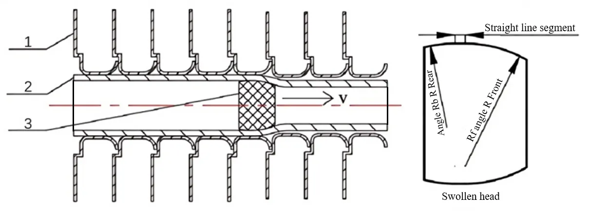
. Geometric position of the heat exchange copper tube and fin.
According to the formula, one can start from the dimensions of the expansion head, heat exchange tubes and fins to reduce the axial force. Reduce the diameter of the expansion head, decrease the wall thickness of the heat exchange tubes or increase the inner diameter of the fin holes. Under the condition that the production requirements and conditions are met, select the appropriate parameters of the expansion joint material.
- (2)
-
Mechanical analysis of the action stage of the straight section of the expansion head:
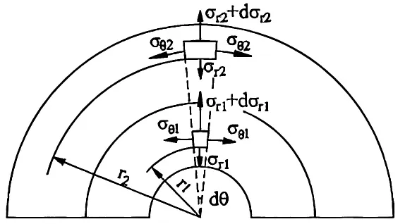
As shown in , when the expansion head moves to contact the heat transfer tube-fin assembly in the straight section, the system enters the steady-state expansion stage. Its mechanical characteristics can be simplified into a double-layer cylinder model for analysis. Among them, the arrow direction is the forward direction of the expansion head, and the dotted box is the main expansion area of the expansion head and the fin. Micro-element bodies with circumferential dθ angles, radial dr Thicknesses, and axial lengths of 1 were respectively cut off from the heat exchange tubes and fins. Their force conditions are shown in .
. Screenshot of the model.
. Forces on heat exchange copper tubes and fin microelements.
When analyzing the force balance of microelements of heat exchange tubes, the axisymmetric force state under the column coordinate system is considered, and the following equilibrium equation system is established:
Since dθ is small and higher-order terms are ignored, it can be simplified as:
In the formula, σ
r1 is the radial stress of the microelement of the heat transfer tube, Pa; and σ
θ1 is the circumferential stress of the microelement of the heat transfer tube, Pa.
According to the third strength theory, there are:
In the formula, σ
S1 is the yield strength of the heat transfer tube, MPa.
According to the formula, its integral is obtained as follows:
According to the boundary conditions σ
rn = −P and σ
rw = 0, the pressure at which the heat transfer tube has maximum plastic deformation:
In the formula, K
1 is the ratio of the outer diameter r
w to the inner diameter r
n of the heat exchange tube when it undergoes maximum plastic deformation [
47].
In the mechanical analysis of the contact between the heat transfer tube and the fin, the equilibrium equation of the radial microelement of the fin is established based on the theory of elastic mechanics. The derivation process is as follows:
It can be simplified as:
In the formula, σ
r2 is the radial stress of the fin microelement, Pa; and σ
θ2 is the circumferential stress of the fin microelement, Pa.
Then the radial strain of the fin microelement is:
The circumferential strain of the fin microelement is:
- (3)
-
Load-unloading stage of the head:
At the end of the expansion process, the system enters the unloading rebound stage when the straight section of the expansion head has completely passed through the contact area and no radial pressure is applied to the rear R-angle. The mechanical behavior during this stage can be described as follows:
The fin buckling amount is $$\Delta_1$$:
Under the action of residual contact pressure P
c, the elastic recovery behavior of the heat exchange tube and fin can be calculated by the following formula:
Combined with the above formula, the residual contact pressure, P
c can be obtained:
5.2. Finite Element Simulation of the Expansion Joint Process of Heat Exchangers
In actual operation, the tube expansion machine is capable of expanding dozens of heat exchange smooth tubes and hundreds of fins simultaneously. To facilitate a more focused study of the expansion process, a simplified model consisting of a single heat exchange tube and five fins.
Since Marc 2017 software does not provide advanced capabilities for establishing three-dimensional models of heat exchangers, a more specialized modeling tool, SolidWorks, is used. SolidWorks is capable of creating accurate three-dimensional models of complex systems, which is crucial for studying the expansion joint process.
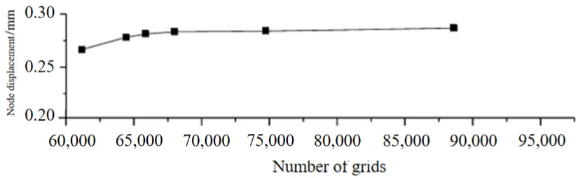
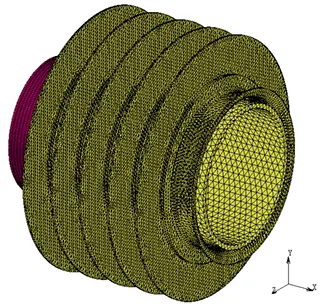
For different numbers of grid models, the required operation time varies. Generally speaking, the operation time will increase exponentially with the number of grid cells. Under the condition of ensuring the accuracy of model calculation, improving the calculation efficiency by simplifying the model is the conventional practice of using finite element simulation. A grid independence analysis was conducted to reduce the influence of the number of grids on the results. The displacement of the same position node of the heat exchange tube was selected as the analysis result, and the curve graph shown in was obtained. As the number of grids increases, the curve gradually grows and flattens. Considering the accuracy of the results, the operation time is reduced, and the number of grids selected is 67,061. The final grid division is shown in .
. Grid independence of the three-dimensional model of the Heat exchanger.
. Mesh division of the three-dimensional overall model of the heat exchanger.
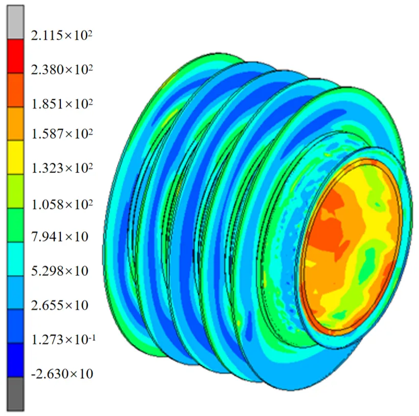
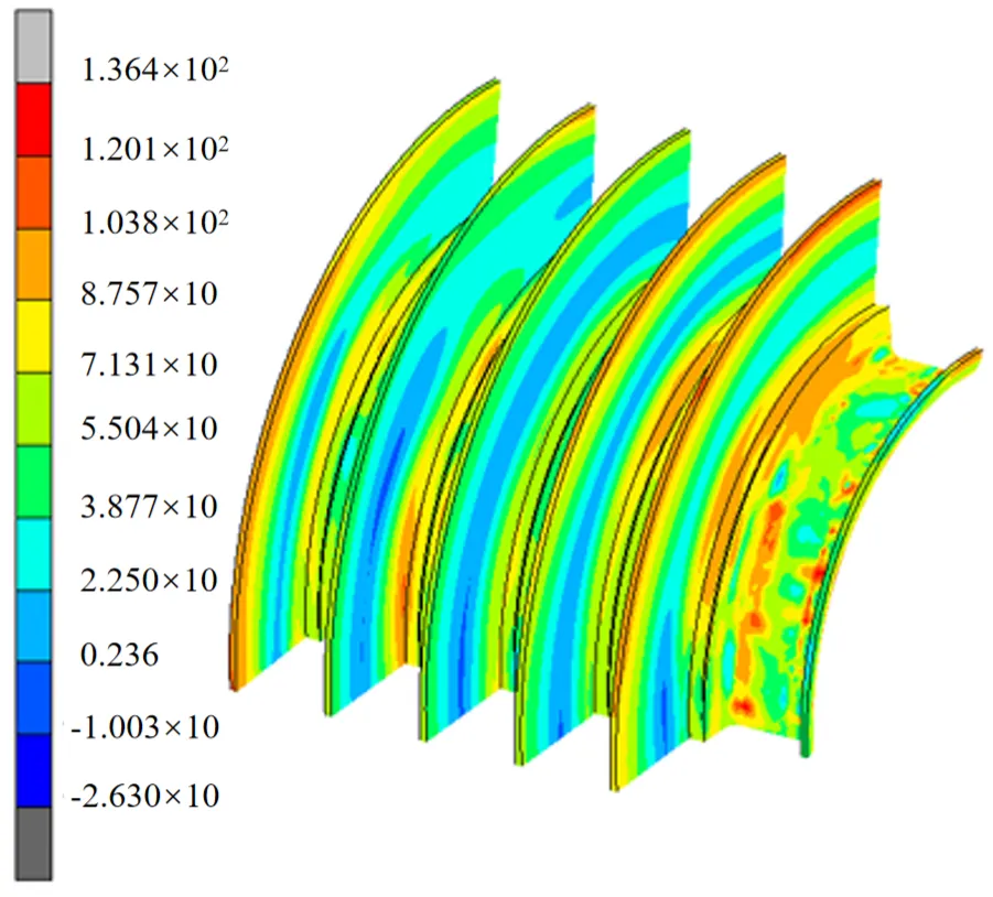
The finite element simulation of the three-dimensional model was completed using the current production parameters, and the corresponding simulation results were obtained. shows an expansion joint—the equal effect diagram of the rear light tube and the fin. As can be seen from the figure, the equivalent stress value of the smooth tube is generally larger than that of the fin. During the entire expansion process, the smooth tube has already yielded and undergone plastic deformation, and most of the fins have also undergone plastic deformation. A quarter of the fin model was cut, as shown in . The equivalent stress distribution of the fins becomes smaller and smaller along the radial direction. Stress concentration mainly occurs at the protrusions and fillets, which are mainly related to the geometry of the fins. Since the fin material is plastic and the fins are not subject to external loads such as alternating loads in the working environment of the heat exchanger, the influence of stress concentration on the strength of the fins can be ignored[
48].
. The overall equal-effect diagram of the light tube and the fin.
. Equal-effect diagram of fins.
When simulating the hydraulic expansion joint of the heat exchanger, the copper tube model was simplified to expedite the computational process without compromising the simulation’s validity. Specifically, a model with five fins was used for the analysis. To ensure that the simplified model accurately represents the real-world scenario, it is necessary to verify the simulation results through comparison with experimental data.
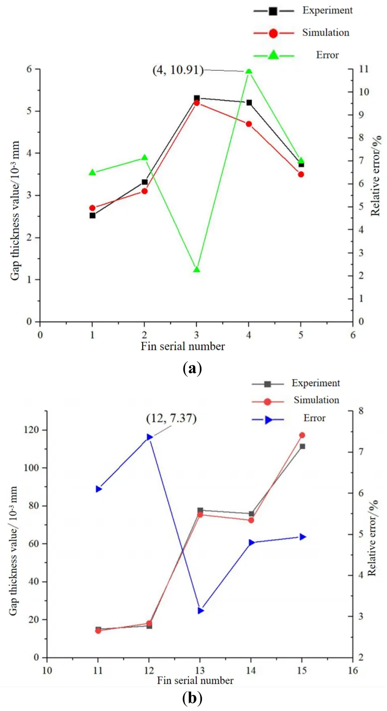
As can be seen from , the simulation result for the gap thickness at the front end of the copper tube is the largest when compared to the experimental result, with a relative error of 10.91%. The relative errors for the remaining four measurement points are all within 10%. At the rear end of the copper tube, the maximum relative error between the simulation result and the experimental data is 7.37%, with all errors still within 10%. The gap thickness values at both the front and rear ends of the copper tube obtained from the simulation are not much different from the experimental results. This indicates that the simulation model is accurate and meets the required accuracy standards. The small discrepancies observed between the simulation and experimental results fall within acceptable limits, confirming that the simulation model is reliable for further analysis and optimization.
. Comparison of gap thickness values between simulation and experiment. (<b>a</b>) Comparison of the thickness values of the gap at the front end of the copper tube; (<b>b</b>) Comparison of the thickness values of the gap at the rear end of the copper tube.
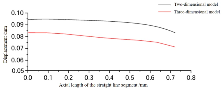
The node displacements of the inner walls of the straight segments of the fins in the three-dimensional and two-dimensional models after expansion were extracted, respectively, and the obtained data are shown in the figure. As shown in . The displacements at different node positions on the straight line segment vary. The displacement gradually decreases along the path from the left end to the right end of the straight line segment. By comparing the displacement situations of the two models, the displacement of the two-dimensional model after the expansion joint is larger, but the difference between the two does not exceed 15%. Moreover, the displacement change trends of the three-dimensional and the two-dimensional models are consistent. It can be considered that the two-dimensional model has a certain degree of correctness. It can be applied to the subsequent optimization of process parameters.
. The linear segment displacement of the fins in the three-dimensional model and the two-dimensional model.
6. Analysis of the Drying Process
6.1. Overview of Drying Process
The presence of residual volatile oil and its associated corrosion mechanisms in the manufacturing process of heat exchangers has emerged as a critical factor impacting product quality. During processing, a substantial amount of mineral oil-based lubricating and cooling medium is utilized to stamp fins and form copper tubes. For aluminum foil stamping, sulfur-containing extreme pressure cutting oil is required, and hydraulic oil is consumed during the bending of copper tubes. In a humid and hot environment, these residual oils can oxidize and degrade, producing 1200 ppm of formic acid and 800 ppm of acetic acid within 30 days. This degradation significantly reduces the pH value at the contact interface from an initial 6.8 to 3.2, leading to corrosion of the copper tubes [
49].
6.2. Constant Temperature Analysis of Heat Exchanger Furnaces
Fin oil and copper tube oil are the primary processing oils for heat exchangers. Although both fall under the category of volatile oils, they exhibit significant differences in physical properties. Laboratory tests indicate that the density of copper tube oil is approximately 9.9% higher than that of fin oil, which directly affects their volatility. Under standard test conditions (120 °C for 10 min), the volatility rates of fin oil and copper tube oil reach at least 42% and 22%, respectively [
50,
51,
52,
53].
However, notable differences exist between the actual production environment and laboratory conditions. The production site operates within a higher temperature range (150–180 °C) and utilizes a shorter drying time (2.5 min). Studies have shown that when the temperature is increased to 180 °C, the activation energy for the volatilization of copper tube oil decreases to 45.2 kJ/mol. According to the Arrhenius equation, each 10 °C increase in temperature can enhance the volatilization rate by a factor of 1.8. Although the tunnel dryer experiences temperature fluctuations of ±8 °C, optimizing the process parameters ensures that the temperature remains above 165 °C for more than 2.5 min, which guarantees the complete vaporization of copper tube oil.
7. The Design of the Production Line Process Equipment System
7.1. The Fixture of the Punching Machine Offline
The function of the chip machine offline robot is to remove the heat exchanger fin from the access mechanism and place it on the conveyor belt. a shows the chip machine offline robot fixture schematic diagram:
. The diagram of the punch offline robot fixture and workpiece positioning. (<b>a</b>) The diagram of the punching line robot fixture. 1. Clamping claw, 2. Fixture connection plate, 3. Guide rail, 4. Cylinder, 5. Baffle; (<b>b</b>) Punching strip offline robot fixture claw groove; (<b>c</b>) Heat exchanger insertion positioning steel needle diagram. 1. Fin, 2. Positioning a steel needle.
The punch line clamp consists of symmetrically arranged clamping jaws, specifically the first and second lower clamping pieces. Each jaw has a clamping part designed to secure the two ends of the positioning pin. The clamping jaws are actuated by a cylinder, which drives the second lower clamping piece to move back and forth [
54,
55].
The punch strip clamping fixture holds the positioning steel needle, with grooves provided on the jaws to facilitate the clamping. Before the fixture clamps the heat exchanger fins, the position of the heat exchanger workpiece must be accurately aligned, as illustrated in b. Upon inserting multiple positioning steel needles, the aluminum sheets that form the condenser can still move vertically. Still, their movement along the X-axis, Y-axis, and around the X-axis, Y-axis, and Z-axis is restricted by the positioning of steel needles. This configuration allows for limited movement in the Z-axis direction.
7.2. The Fixture of the End Plate Robot
The function of the end plate robot fixture is to install the end plate on both sides of the heat exchanger fin, restrain the movement of the heat exchanger fin in the Z-axis direction, and achieve the complete positioning of the heat exchanger fin. As shown in , the end plate robot clamps the end plate.
The connecting middle beam is provided with a piston push head extending to the clamping position of the end plate. In the end plate of the robot forearm, the piston push head is pushed by the piston push head driving device. The pushing power member is fixed on the connecting middle beam, and the piston push head is fixed at the output end of the pushing power member.
The end plate positions the workpiece by positioning pillars A, B, and C and a jaw side plate. The jaw side plate clamps the workpiece from both sides towards the middle, limiting its movement and rotation in the X-axis direction. Pillars A, B and C restrict the workpiece’s movement and rotation in the Y-axis direction [
56].
. End plate robot fixture. (<b>a</b>) Schematic diagram of end plate robot operation. 1. Clamping claw, 2. Piston push head, 3. End plate; (<b>b</b>) Fixture diagram of end plate robot. 1. Positioning column A, 2. Positioning column B, 3. Positioning column C.
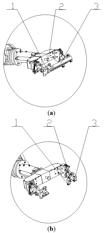
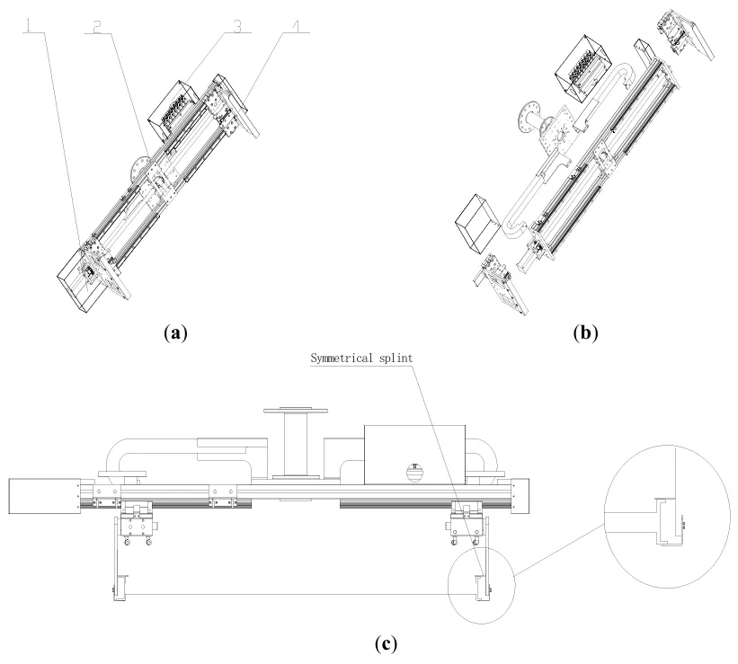
The function of the dryer upper and lower line fixture is divided into two kinds, one is to remove the heat exchanger that has completed the tube expansion process from the tube expansion station, the second is to remove the heat exchanger that has completed the drying from the drying conveyor belt, as shown in a is the schematic diagram of the dryer upper and lower line fixture [
57].
Figure 27. Schematic diagram of drying machine upper and lower line fixture. (<b>a</b>) dryer upper and lower line fixture diagram. 1. Motor, 2. Slide rail, 3. Electric control box, 4. Clamp plate; (<b>b</b>) dryer upper and lower line fixture explosion diagram; (<b>c</b>) Working drawings of dryer upper and lower line fixtures.
As shown in c, the fixture plate on the drying line utilizes a double-sided symmetrical clamp, which facilitates the positioning of the heat exchanger during clamping and transportation. A thin layer of adhesive film is applied to the clamp plate to enhance friction between the clamp plate and the end plates of the heat exchanger. The symmetrical clamp plates on both sides of the fixture secure the end plates at both ends of the heat exchanger, thereby restricting its rotation and movement along the Y and Z axes, while allowing rotation along the X axis. To control movement along the X axis, a thin layer of adhesive film is applied to the clamp plate to increase friction between the clamp plate and the end plates of the heat exchanger. Given that the upper and lower line robots of the dryer move slowly, restriction of the X-axis movement degree of freedom is not necessary [
58].
7.4. The Maintenance and Control of Clamping Force
PID control is widely used in industrial process control (such as temperature, pressure, flow, etc.) due to its simple algorithm and strong robustness. It can maintain high reliability, especially in complex systems where mathematical models are difficult to obtain precisely. Its core advantage lies in the fact that it can adapt to different control requirements by adjusting three parameters: proportional coefficient (Kp), integral time (TI), and differential time (TD).
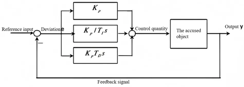
PID is the abbreviation of the first letters of Proportion (proportion), Integral (integral), and Differential (differential). It is a closed-loop control algorithm that integrates the three links of proportion, integral and differential. In a closed-loop control system, a feedback loop is introduced. By taking advantage of the deviation between the output (actual value) and the input (target value), the system is controlled to prevent deviation from the predetermined target. The closed-loop control system, also known as the feedback control system, has a specific control process as shown in the following figure:
The proportional link can proportionally reflect the deviation signal of the control system; that is, the output is proportional to the input deviation, which can be used to reduce the deviation of the system. The formula for this stage is as follows:
u—Output
K
p—Proportional coefficient
e—Deviation.
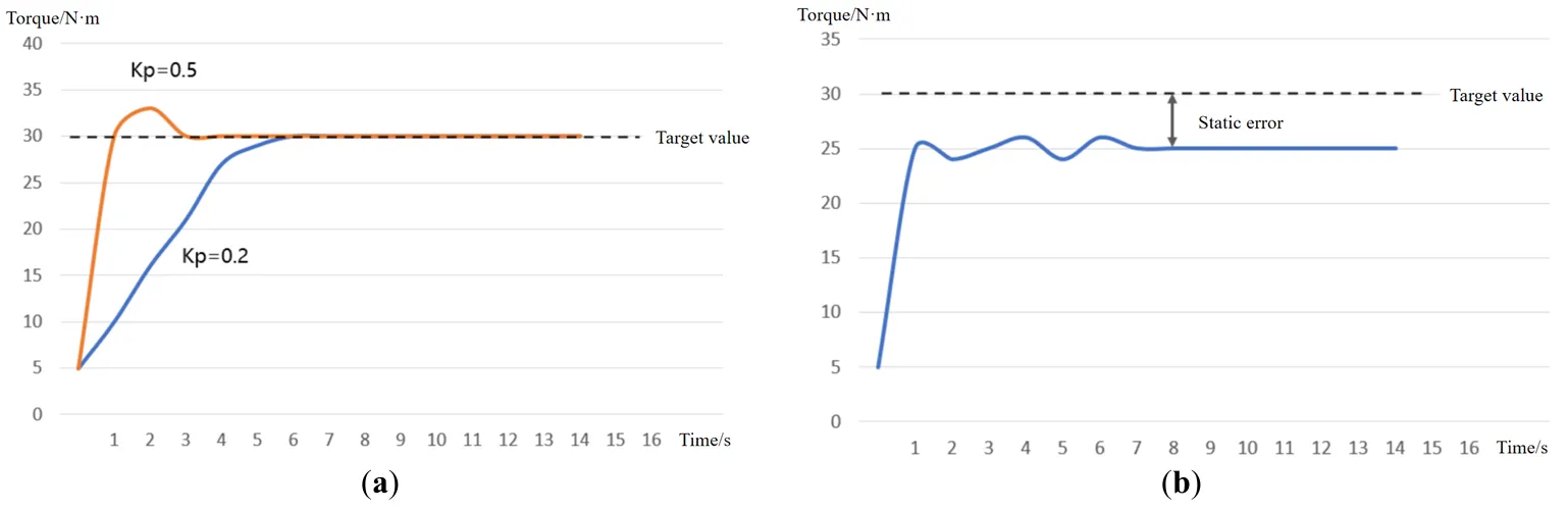
In practical applications, if only the proportional link is controlled, it may cause a problem in the system: static error. Static error refers to the deviation between the target and the measured values when the system control process tends to stabilize [
59].
The integration stage can integrate the deviation E. The integration stage will keep functioning as long as there is a deviation. It mainly eliminates static errors and improves the system’s accuracy. After introducing the integration link, the formula of proportion + integration link is as follows:
From the above formula, it can be known that when the integration coefficient K
i or the cumulative deviation is larger, the output will be greater, and the time for the system to eliminate static errors will be shorter.
During the process of clamping workpieces with fixtures, the power element must consistently maintain a certain clamping force to secure the workpiece. A servo motor in conjunction with a PID control algorithm is employed for the clamping force of robotic fixtures, as illustrated in . The servo motor provides precise torque output, and strain gauge force sensors are installed on the fixture. These sensors operate based on the principle of resistive strain, which allows them to convert changes in strain on mechanical components into changes in resistance. This conversion enables the measurement of physical quantities such as force, pressure, and torque [
60,
61,
62]. As shown in , the Error curve graph of the PID algorithm is presented.
. Error curve graph of the PID algorithm. (<b>a</b>) Proportional link error curve graph; (<b>b</b>) Error elimination curve graph in the integration stage.
First, the target clamping force threshold is set based on the material, weight, and friction coefficient of the object to be clamped. When the servo motor detects contact with the object, it drives the gripper to close quickly until it contacts the surface, as indicated by a force sensor trigger. Subsequently, real-time force feedback is continuously provided, with the force sensor monitoring the actual clamping force between the gripper and the object’s contact surface at a high sampling frequency (typically 1 kHz or higher). The sensor data is transmitted in real-time to the controller via a communication interface [
63].
Error calculation:
PID regulate:
Motor torque adjustment: The controller adjusts the output torque of the servo motor in real time according to the PID output to ensure that the actual clamping force is always close to the target value. If the object slides or deforms (resulting in the actual F falling), the motor automatically increases the torque compensation. In the formula, the unit of F is N and the unit of torque is N·m.
8. Design Methodologies for Production Lines
8.1. The Design of the System Architecture
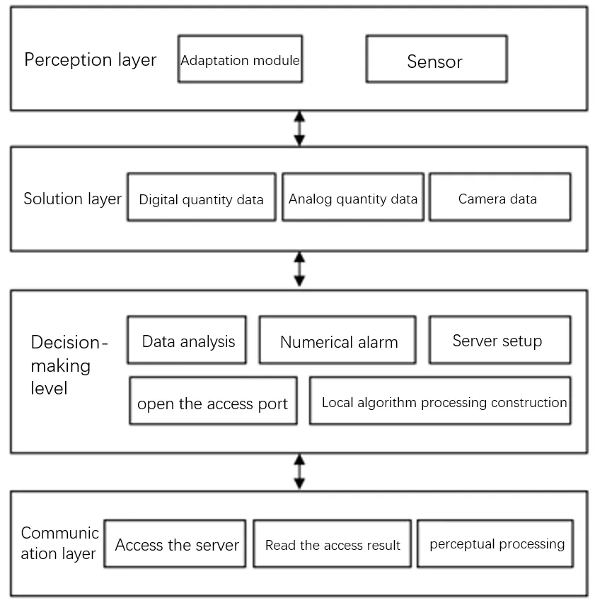
As shown in , this paper adopts a hierarchical architecture design, comprising four core components: the perception layer, the solution layer, the decision-making layer, and the communication layer.
- 1.
-
Perception Layer: This layer is responsible for the real-time collection and data conversion of environmental physical quantities through adaptation modules and sensor arrays. It enhances the multi-source information perception capability, ensuring comprehensive environmental data acquisition.
- 2.
-
Solution Layer: The solution layer handles the real-time processing and noise suppression of digital, analog, and visual data. This ensures the reliability and security of the data, maintaining the integrity of the information as it is processed.
- 3.
-
Decision-Making Layer: This layer performs data analysis, issues abnormal alarms, and constructs a hybrid computing environment. Additionally, it provides system access interfaces, enabling interaction with other system components and external systems.
- 4.
-
Communication Layer: The communication layer ensures the reliable transmission of server interactions and perceived data using efficient transmission protocols. This completes the closed-loop data flow, facilitating seamless and reliable data exchange throughout the system.
These layers form a robust framework capable of real-time data collection, processing, analysis, and transmission, ensuring the system’s overall efficiency and reliability [
64].
. System architecture diagram.
8.2.1. Intelligent Perception System for Production Lines
Multi-dimensional data acquisition can integrate various sensors, such as those for temperature, pressure, flow, vibration, and corrosion, to monitor key parameters of the heat exchanger in real-time. These parameters include the inlet and outlet temperatures of the refrigerant, heat exchange efficiency, and the degree of scaling on the tube wall. By replacing traditional distributed sensors, this approach eliminates data silos and provides a comprehensive operational profile.
Edge-side data fusion and preprocessing are employed to perform data filtering (such as noise removal), feature extraction (such as the rate of change in temperature difference), and anomaly detection (such as a sudden increase in pressure drop) within the module. This process reduces the amount of data that needs to be uploaded by more than 50%, lowering the load on cloud computing and enhancing response speed. The processed data is transmitted in real-time to the central controller or edge computing unit through standard interfaces (such as Modbus, CAN bus), enabling dynamic regulation (such as adjusting the opening degree of the expansion valve). This closed-loop control system avoids the lag inherent in traditional open-loop systems.
Temperature Sensing System: Infrared thermometers and PT100 temperature sensor arrays are installed at key workstations, such as copper tube processing, fin stamping, and brazing, to monitor material and process temperatures. The temperature measurement range should cover −20 ℃ to 600 ℃, with an accuracy of ±0.5 ℃.
Pressure Monitoring System: Piezoresistive pressure sensors are installed in processes such as hydraulic forming and air tightness testing. These sensors, with a range of 0–10 MPa and an accuracy of 0.25%FS, monitor processing and system pressures in real-time.
Visual inspection system: It adopts industrial cameras combined with edge detection machine vision algorithms to conduct online inspection of parameters such as the fin spacing of heat exchangers, the straightness of copper tubes, and welding quality. The resolution of the camera should be at least 5 million pixels and be equipped with a ring light source to ensure high imaging quality.
Vibration and Noise Monitoring: ADXL1002BCPZ MEMS acceleration sensors are installed in processes prone to mechanical vibration, such as stamping and tube expansion, to monitor the operating status of the equipment. These sensors should have a frequency response range of 10 Hz to 10 kHz.
By incorporating these systems, the heat exchanger manufacturing process can achieve higher precision, reliability, and efficiency through advanced monitoring and control techniques [
65].
8.2.2. Edge Computing and Internet of Things Module Design
Local real-time processing via edge computing enables direct handling of sensor data (such as temperature, pressure, flow rate,
etc.) on edge devices located close to the heat exchanger (such as gateways and embedded modules). This approach reduces reliance on cloud computing and lowers latency. It allows for rapid response to anomalies (such as refrigerant leakage and scaling warnings), prevents the spread of faults due to network delays, and enhances system reliability.
Edge Device Layer: This layer is deployed at key nodes of the production line (such as brazing machines, tube expansion machines, and inspection stations). It is equipped with NVIDIA Jetson AGX Xavier high-performance embedded processors that support real-time data acquisition and local computing. TensorFlow Lite lightweight AI inference frameworks are integrated to run models for device status monitoring and defect detection.
Edge Gateway Layer: This layer uses Advantech UNO series industrial-grade edge computing gateways equipped with Cortex-A72 multi-core ARM processors. These gateways run on Linux or real-time operating systems (RT-Linux). They are responsible for data aggregation, protocol conversion (e.g., Modbus to MQTT/OPC UA), and data caching, with support for SD card or SSD storage expansion.
Edge Server Layer: Deployed at the workshop level, this layer employs Siemens SIMATIC IPC industrial servers. It runs Kubernetes edge clusters and supports data preprocessing and process optimization algorithms containerized microservices. InfluxDB Local databases are provided to store short-term historical data (7 to 30 days), supporting rapid query and analysis.
Remote Monitoring and Collaboration via IoT: The Internet of Things (IoT) modules upload heat exchanger data to the cloud platform, enabling coordination with fans and pumps, multi-device linkage and cross-regional management. Operation and maintenance personnel can view the real-time operational status and remotely debug parameters through mobile phones or computers, reducing on-site inspection costs.
By implementing this hierarchical architecture, the system can achieve rapid anomaly detection and response, efficient data processing, and enhanced system reliability, all while reducing operational costs and dependency on cloud infrastructure. This setup ensures a robust and efficient monitoring and control system for heat exchanger production and maintenance.
8.2.3. The Module of Data Acquisition and Decision-Making
The data acquisition and decision-making module of the central air conditioning heat exchanger serves as the “intelligent brain” of the system. It is responsible for real-time data aggregation, analysis, modeling, and dynamic control. This module integrates data from the heat exchanger body sensors (temperature, pressure, flow), environmental sensors (temperature and humidity), and equipment status signals (valve opening, compressor frequency). Unifying data formats (such as JSON/OPC UA) addresses the compatibility issues associated with multi-source heterogeneous data.
Dynamic Energy Efficiency Analysis and Decision-Making: The system calculates key indicators (such as the heat transfer coefficient and the Coefficient of Performance (COP) energy efficiency ratio) in real-time. PID algorithm control instructions are generated through preset rule bases or Long Short-Term Memory (LSTM) prediction AI models. These instructions automatically adjust parameters such as refrigerant flow rate and fan speed, ensuring that the system operates within the optimal energy efficiency range at all times [
66].
Data Acquisition Architecture: The architecture adopts a three-tier system comprising the edge layer, workshop layer, and cloud layer:
- 1.
-
Edge Layer: Intelligent sensors and PLCs (Programmable Logic Controllers) are deployed at the device level, responsible for millisecond-level raw data acquisition.
- 2.
-
Workshop Layer: The industrial gateway handles data cleaning, format conversion, and short-term storage.
- 3.
-
Cloud Layer: The big data platform is used for long-term storage and in-depth analysis.
High-Speed Acquisition Technology: The system employs high-speed acquisition for key process parameters (such as welding current and pressure), achieving millisecond-level acquisition. FPGA (Field-Programmable Gate Array) technology is also utilized to enable multi-channel synchronous acquisition with a synchronization accuracy of ±10 μs. To handle network fluctuations, a circular buffer is equipped with a default cache capacity of 4 h of data [
67].
This architecture and technology framework supports:
Real-Time Data Processing: Enables direct and immediate processing of sensor data at the edge, enhancing responsiveness and reliability.
Dynamic Control: Automatically adjusts operational parameters to maintain optimal energy efficiency.
Comprehensive Data Management: Ensures seamless data flow and compatibility across different layers and formats.
Robust Fault Handling: Uses high-speed acquisition and buffering to prevent data loss during network interruptions.
The central air conditioning heat exchanger can achieve superior operational efficiency, reliability, and energy management by implementing such a robust system.
9. Applications
The practical application effect of the intelligent production line case is verified through the comparison and analysis of specific production data. The intelligent production line significantly shortens the production cycle, improves product yield, and reduces production costs. By leveraging whole-process automation, real-time data-driven decision-making, and precise control of materials and energy consumption, the intelligent production line exhibits advantages in six key dimensions: research and development, efficiency, quality, cost, flexibility, and environmental protection. As a result, the air conditioning manufacturing industry has identified the development of intelligent production lines as a core direction at the provincial level. A comparison of the production efficiency between intelligent production and traditional production lines is shown in Table 3 and Table 4.
Table 3.
Comparison of production line transformation productivity.
| Category |
Daily Production
Time (min) |
Daily Output
(Unit) |
Crew
(Person) |
Production
Takt Time(S/Unit) |
UPPH |
| Traditional |
|
|
|
|
|
Production
Line
|
600 |
820 |
47 |
660 |
2.03 |
| Intelligent |
|
|
|
|
|
Production
Line
|
600 |
1333 |
20 |
280 |
7.75 |
UPPH (Units Per Person per Hour) is one of the core indicators for measuring production efficiency in the manufacturing industry, indicating the quantity of qualified products produced per person per hour. It directly reflects the rationality of personnel allocation and operational efficiency, and is often used in production planning, cost control and performance management.
Table 4.
Comparison between Traditional Production and Smart Production Lines.
| Comparison Dimension |
Traditional Manual Production |
AI intelligent Manufacturing |
Efficiency Improvement/Advantage |
| Production speed |
The average is 60 to 120 s per unit |
8 s per unit |
Increase by 7 to 15 times |
| Average daily production capacity |
The single line is approximately 3000 units per day |
The single line is 12,000 units per day |
Increase by 300% |
| Human resource demand |
200 people per production line |
The dark factory is unattended 24 h a day |
Reduce the workforce by more than 90% |
| Product qualification rate |
About 97% |
99.9% |
The quality inspection accuracy is eight times that of manual inspection |
| Energy utilization rate |
Conventional energy consumption, no dynamic optimization |
Photovoltaic energy storage combined with AI dispatching has reduced carbon emissions by 85.7% |
Annual carbon reduction exceeds 6000 tons |
| Flexible production level |
It takes 45 min to change the cable and only supports large quantities of a single model |
3-min quick model change, multi-model mixed production line |
Respond to customized requirements |
The intelligent production line has achieved a systematic leap over the traditional production mode by deeply integrating the Internet of Things and robot technology. In terms of efficiency, the production time of a single air conditioner has been reduced from the traditional manual 60–120 s to 8 s, and the daily production capacity of a single line has increased by 300% (reaching 12,000 units per day), achieving an exponential speed-up. The labor cost has been revolutionarily reduced. The 24-h unmanned operation mode of the dark factory reduces the reliance on labor by more than 90% compared with the traditional production line. Breakthrough progress has been made in quality control. AI visual quality inspection has raised the product qualification rate to 99.9%. Multi-spectral imaging technology has achieved 100% automatic error prevention for components, and the defect interception accuracy is more than eight times that of manual inspection.
The intelligent production line demonstrates a clear superiority over traditional production methods across multiple key dimensions, including efficiency, cost, quality control, environmental impact, and flexibility. This shift to intelligent manufacturing enhances production capabilities and aligns with modern sustainability and efficiency goals, paving the way for future advancements in the air conditioning manufacturing industry.
10. Conclusions
This study presents a fully integrated intelligent production line for multi-split central air conditioning systems, which addresses inefficiencies in traditional production methods, including low automation, high energy consumption, and unstable product quality. This design establishes a seamless closed-loop system by leveraging advanced Industry 4.0 technologies such as sensor networks, programmable logic controllers (PLCs), industrial Ethernet, edge computing, and digital twin frameworks. This system enables real-time perception, efficient data transmission, intelligent analysis, decision-making, and automatic execution, thereby optimizing the production process and enhancing overall operational performance. Integrating these cutting-edge technologies fosters significant improvements in automation, energy efficiency, and product consistency, enabling smarter and more sustainable manufacturing solutions for multi-split central air conditioning systems.
- (1)
-
One of this research’s key innovations is optimising the production line layout, which integrates multiple subsystems into a cohesive, automated workflow. These subsystems include the punching machine feeding system, end plate installation system, tube insertion system, tube expansion system, and drying system. Combining these subsystems has streamlined the production process, enhancing both efficiency and precision. The intelligent management platform, built on a modular architecture, enables comprehensive monitoring throughout the production process. This platform ensures operational transparency, allows for predictive maintenance, and supports adaptive process optimization, helping to maintain high levels of performance and reduce downtime. Furthermore, the PID control algorithm has been implemented to improve the accuracy of key processes, particularly in areas such as clamping force retention and pipe expansion. This control algorithm ensures that these processes are executed with greater precision, contributing to overall production consistency and quality. Additionally, a finite element simulation of the pipe expansion process was conducted to better understand the mechanical behavior during the process and refine the design. This simulation supports the development of more effective fixtures and process parameters, ensuring that the pipe expansion process operates within optimal conditions.
- (2)
-
Compared to traditional methods, this intelligent production system has achieved a 300% increase in daily production capacity, with output rising from 3000 units per day to 12,000 units per day. The shift to a 24-h unmanned “dark factory” operation has resulted in a labor cost reduction of over 90%, demonstrating significant operational cost savings. The integration of an artificial intelligence quality inspection system has led to a product qualification rate of 99.9%, ensuring consistently high-quality products with minimal defects. Moreover, dynamic optimization has substantially improved energy efficiency, further reducing costs. By incorporating photovoltaic energy storage, the system has achieved an 85.7% reduction in carbon emissions, contributing to sustainability goals and positioning the production line as a more environmentally responsible solution.
- (3)
-
In addition to its direct industrial applications, this study also makes a valuable contribution to the broader field of smart manufacturing by demonstrating the feasibility and benefits of digital-physical integration. The developed methods, such as the hierarchical system architecture and edge-cloud collaboration framework, are not only beneficial for multi-split central air conditioning production but can also be adapted to other manufacturing fields. This adaptability enhances the scalability and interoperability of the system, making it a versatile solution that can be applied across various industries to improve automation and operational efficiency.
Author Contributions
Conceptualization, Z.Z. and Y.F. (Yuewen Feng); Methodology, Y.H. and X.M.; Software, B.L. and G.L.; Validation, S.C. and G.J.; Formal Analysis, X.S. and Y.Z.; Investigation, X.Y. (Xu Yan) , X.Y. (Xianxin Yin) and S.W.; Data Curation, J.W. and Q.B.; Writing—Original Draft Preparation, Y.F. (Yudi Fei); Writing—Review & Editing, C.L.; Funding Acquisition, C.L.
Ethics Statement
Not applicable.
Informed Consent Statement
Not applicable.
Data Availability Statement
Not applicable.
Funding
This study was financially Supported by National Natural Science Foundation of China (Grant Nos.52375447, 52305477 and 52105457), the Shandong Provincial Natural Science Foundation of China (Grant Nos. ZR2023QE057, ZR2024QE100 and ZR2024ME255), the Shandong Provincial Science and Technology SMEs Innovation Capacity Improvement Project (Grant No. 2024TSGC0239), the Special Fund of Taishan Scholars Project, the Shandong Province Youth Science and Technology Talent Support Project (Grant No.SDAST2024QTA043), and the Open Funding of Key Lab of Industrial Fluid Energy Conservation and Pollution Control, Ministry of Education (Grant Nos. CK-2024-0031, CK-2024-0035 and CK-2024-0036).
Declaration of Competing Interest
The authors declare that they have no known competing financial interests or personal relationships that could have appeared to influence the work reported in this paper.
References
-
1.
Dani S, Rahman A, Jin J, Kulkarni A. Cloud-Empowered Data-Centric Paradigm for Smart Manufacturing.
Machines 2023,
11, 451. doi:10.3390/machines11040451.
[Google Scholar]
-
2.
Davis J, Edgar T, Porter J, Bernaden J, Sarli M. Smart manufacturing, manufacturing intelligence and demand-dynamic performance.
Comput. Chem. Eng. 2012,
47, 145–156. doi:10.1016/j.compchemeng.2012.06.037.
[Google Scholar]
-
3.
Alhama Blanco PJ, Abu-Dakka FJ, Abderrahim M. Practical Use of Robot Manipulators as Intelligent Manufacturing Systems.
Sensors 2018,
18, 2877. doi:10.3390/s18092877.
[Google Scholar]
-
4.
Ding K, Lei JY, Felix TSC, Hui J, Zhang F, Wang Y. Hidden Markov model-based autonomous manufacturing task orchestration in smart shop floors.
Robot. Comput. Integr. Manuf. 2020,
61, 101845.1–101845.9. doi:10.1016/j.rcim.2019.101845.
[Google Scholar]
-
5.
Ahmmed MS, Isanaka SP, Liou F. Promoting Synergies to Improve Manufacturing Efficiency in Industrial Material Processing: A Systematic Review of Industry 4.0 and AI.
Machines 2024,
12, 681. doi:10.3390/machines12100681.
[Google Scholar]
-
6.
Errandonea I, Beltrán S, Arrizabalaga S. Digital Twin for maintenance: A literature review.
Comput. Ind. 2020,
123, 103316. doi:10.1016/j.compind.2020.103316.
[Google Scholar]
-
7.
Farbiz F, Habibullah MS, Hamadicharef B, Maszczyk T, Aggarwal S. Knowledge-embedded machine learning and its applications in smart manufacturing.
J. Intell. Manuf. 2023,
34, 2889–2906. doi:10.1007/s10845-022-01973-6.
[Google Scholar]
-
8.
Hu S, Li C, Li B, Yang M, Wang X, Gao T, et al. Digital Twins Enabling Intelligent Manufacturing: From Methodology to Application.
Intell. Sustain. Manuf. 2024,
1, 10007. doi:10.35534/ism.2024.10007.
[Google Scholar]
-
9.
Suleiman DY, Li Q, Li B, Zhang Y, Zhang B, Liu D, et al. Digital Twin and Artificial Intelligence in Machining: A Bibliometric Analysis.
Intell. Sustain. Manuf. 2025,
2, 10005. doi:10.70322/ism.2025.10005.
[Google Scholar]
-
10.
Ryalat M, ElMoaqet H, AlFaouri M. Design of a Smart Factory Based on Cyber-Physical Systems and Internet of Things towards Industry 4.0.
Appl. Sci. 2023,
13, 2156. doi:10.3390/app13042156.
[Google Scholar]
-
11.
Wang L, Chen X, Liu Q. A Lightweight Intelligent Manufacturing System Based on Cloud Computing for Plate Production.
Mob. Netw. Appl. 2017,
22, 1170–1181. doi:10.1007/s11036-017-0862-5.
[Google Scholar]
-
12.
Zheng P, Wang H, Sang Z, Zhong RY, Liu Y, Liu C, et al. Smart manufacturing systems for Industry 4.0: Conceptual framework, scenarios, and future perspectives.
Front. Mech. Eng. 2018,
13, 137–150. doi:10.1007/s11465-018-0499-5.
[Google Scholar]
-
13.
Mienye ID, Sun Y. A Survey of Ensemble Learning: Concepts, Algorithms, Applications, and Prospects.
IEEE 2022,
10, 99129-99149. doi:10.1109/ACCESS.2022.3207287.
[Google Scholar]
-
14.
Wang JL, Xu CQ, Zhang J, Zhong R. Big data analytics for intelligent manufacturing systems: A review.
J. Manuf. Syst. 2022,
62, 738–752. doi:10.1016/j.jmsy.2021.03.005.
[Google Scholar]
-
15.
Huang JT, Huang SH, Moghaddam SK, Yuqian Lu Y, Wang G, Yan Y, et al. Deep Reinforcement Learning-Based Dynamic Reconfiguration Planning for Digital Twin-Driven Smart Manufacturing Systems with Reconfigurable Machine Tools.
IEEE Trans. Ind. Inform. 2024,
20, 13135–13146. doi:10.1109/TII.2024.3431095.
[Google Scholar]
-
16.
Huang Z, Fey M, Liu C, Beysel E, Xu X, Brecher C, et al. Hybrid learning-based digital twin for manufacturing process: Modeling framework and implementation.
Robot. Comput. -Integr. Manuf. 2023,
82, 102545. doi:10.1016/j.rcim.2023.102545.
[Google Scholar]
-
17.
Çınar ZM, Abdussalam Nuhu A, Zeeshan Q, Korhan O, Asmael M, Safaei B. Machine Learning in Predictive Maintenance towards Sustainable Smart Manufacturing in Industry 4.0.
Sustainability 2020,
12, 8211. doi:10.3390/su12198211.
[Google Scholar]
-
18.
Zhang J, Kang X, Ye Z,
Liu L,
Tao G,
Cao H. Development and testing of a wireless smart toolholder with multi-sensor fusion.
Front. Mech. Eng. 2023,
18, 55. doi:10.1007/s11465-023-0774-y.
[Google Scholar]
-
19.
Chen S, Huang Z, Guo H. An End-to-End Deep Learning Method for Dynamic Job Shop Scheduling Problem.
Machines 2022,
10, 573. doi:10.3390/machines10070573.
[Google Scholar]
-
20.
Bi ZM, Liu YF, Krider J, Buckland J, Whiteman A, Beachy D, et al. Real-time force monitoring of smart grippers for Internet of Things (IoT) applications.
J. Ind. Inf. Integr. 2018,
11, 19–28. doi:10.1016/j.jii.2018.02.004.
[Google Scholar]
-
21.
Wu L, Zhang Y, Liu Z, Qin A, Zhang C, Song X, et al. Intelligent ManufacturingFactory: A Bibliometric Analysis of Global Research Hotspots and Progress.
Intell. Sustain. Manuf. 2024,
1, 10018. doi:10.70322/ism.2024.10018.
[Google Scholar]
-
22.
Velandia DMS, Kaur N, Whittow WG, Conway PP, West AA. Towards industrial internet of things: Crankshaft monitoring, traceability and tracking using RFID.
Robot. Comput. -Integr. Manuf. 2016,
41, 66–77. doi:10.1016/j.rcim.2016.02.004.
[Google Scholar]
-
23.
Wang H, Luo H, Ren L, Huo M, Jiang Y, Kaynak O. Data-Driven Design of Distributed Monitoring and Optimization System for Manufacturing Systems.
IEEE Trans. Ind. Inform. 2024,
20, 9455–9464. doi:10.1109/TII.2024.3383491.
[Google Scholar]
-
24.
Ding K, Zhang Y, Chan FTS, Zhang C, Lv J, Liu Q. A cyber-physical production monitoring service system for energy-aware collaborative production monitoring in a smart shop floor.
J. Clean. Prod. 2021,
297, 126599. doi:10.1016/j.jclepro.2021.126599.
[Google Scholar]
-
25.
Meng ZZ, Wu ZP, Gray J. RFID-Based Object-Centric Data Management Framework for Smart Manufacturing Applications.
IEEE Internet Things J. 2019,
6, 2706–2716. doi:10.1109/JIOT.2018.2873426.
[Google Scholar]
-
26.
Wang XQ, Liu MZ, Liu CH, Ling L, Zhang X. Data-driven and Knowledge-based predictive maintenance method for industrial robots for the production stability of intelligent manufacturing.
Expert Syst. Appl. 2023,
234, 121136.1–121136.20. doi:10.1016/j.eswa.2023.121136.
[Google Scholar]
-
27.
Zhang XY, Ming XG, Bao YG. A flexible smart manufacturing system in mass personalization manufacturing model based on multi-module-platform, multi-virtual-unit, and multi-production-line.
Comput. Ind. Eng. 2022,
171, 108379. doi:10.1016/j.cie.2022.108379.
[Google Scholar]
-
28.
Liu Q, Leng JW, Yan DX, Zhang D, Wei L, Yu A. Digital twin-based designing of the configuration, motion, control, and optimization model of a flow-type smart manufacturing system.
J. Manuf. Syst. 2021,
58, 52–64. doi:10.1016/j.jmsy.2020.04.012.
[Google Scholar]
-
29.
Wu QC, Mao YS, Chen JX, Wang C. Application Research of Digital Twin-Driven Ship Intelligent Manufacturing System: Pipe Machining Production Line.
J. Mar. Sci. Eng. 2021,
9, 338. doi:10.3390/jmse9030338.
[Google Scholar]
-
30.
Yang J, Son YH, Lee D, Noh SD. Digital Twin-Based Integrated Assessment of Flexible and Reconfigurable Automotive Part Production Lines.
Machines 2022,
10, 75. doi:10.3390/machines10020075.
[Google Scholar]
-
31.
Leng J, Chen Z, Sha W, Lin Z, Lin J, Liu Q. Digital twins-based flexible operating of open architecture production line for individualized manufacturing.
Adv. Eng. Inform. 2022,
53, 101676. doi:10.1016/j.aei.2022.101676.
[Google Scholar]
-
32.
EL Ghadoui M, Mouchtachi A, Majdoul R. A hybrid optimization approach for intelligent manufacturing in plastic injection molding by using artificial neural network and genetic algorithm.
Sci. Rep. 2023,
13, 21817. doi:10.1038/s41598-023-48679-0.
[Google Scholar]
-
33.
Kim YG, Lee S, Son J, Bae H, Do Chung B. Multi-agent system and reinforcement learning approach for distributed intelligence in a flexible smart manufacturing system.
J. Manuf. Syst. 2020,
57, 440–450. doi:10.1016/j.jmsy.2020.11.004.
[Google Scholar]
-
34.
Yin H, Huang X, Cao E. A Cloud-Edge-Based Multi-Objective Task Scheduling Approach for Smart Manufacturing Lines.
J. Grid. Comput. 2024,
22, 9. doi:10.1007/s10723-023-09723-5.
[Google Scholar]
-
35.
Ling S, Guo D, Li M, Rong Y, Huang GQ. Heterogeneous demand–capacity synchronization for smart assembly cell line based on artificial intelligence-enabled IIoT.
J. Intell. Manuf. 2024,
35, 539–554. doi:10.1007/s10845-022-02050-8.
[Google Scholar]
-
36.
Yuan D, Tang D, Ni Y, Li X, Gao Z, Yu W, et al. A Forming Line for the Inner Shell of a Central Air Conditioning Unit. CN Patent 114227280A, 25 March 2022.
-
37.
Wang H, Zhou Z, Feng Y, Zhang Y, Ma X, Li B, et al. Central air conditioning indoor machine intelligent assembly line and coating system design.
Manuf. Technol. Mach. Tools 2025,
10, 186–198. doi:10.19287/j.mtmt.1005-2402.2025.10.019.
[Google Scholar]
-
38.
Saari LM, Kääriäinen J, Ylikerälä M. Maturity Model for the Manufacturing Industry with Case Experiences.
Intell. Sustain. Manuf. 2024,
1, 10010. doi:10.35534/ism.2024.10010.
[Google Scholar]
-
39.
Chen W. Intelligent manufacturing production line data monitoring system for industrial internet of things.
Comput. Commun. 2020,
151, 31–41. doi:10.1016/j.comcom.2019.12.035.
[Google Scholar]
-
40.
Chen L, Zheng Y, Cai Z, Zhu H. Fin Type Heat Exchanger for Central Air Conditioner. CN Patent 222799175U, 25 April 2025.
-
41.
Fan Z. The Flat Tube Heat Exchanger Tube Expanding Process Integration Research. Master’s Thesis, Wuhan University of Science and Technology, Wuhan, China, 2023.
-
42.
Tang D, Li D, Peng Y. Optimization to the tube–fin contact status of the tube expansion process.
J. Mater. Process. Technol. 2011,
211, 573–577. doi:10.1016/j.jmatprotec.2010.11.010.
[Google Scholar]
-
43.
Ma DB, Qu MF. Research on on-line Monitoring Method of Automatic Production Line based on Industrial Internet of Things. In Proceedings of the 2020 IEEE International Conference on Industrial Application of Artificial Intelligence (IAAI), Harbin, China, 25–27 December 2020, pp. 492–496.
-
44.
Ni C, Wang X, Deng X. Radiator Fin Stamping Forming Machine. CN Patent 117505711A, 6 February 2024.
-
45.
Jie Chu J, Zhu M, You Y, Jin T. Air conditioning fin forming process and mold design.
Mold Ind. 2023,
49, 27–31. doi:10.16787/j.cnki.1001-2168.dmi.2023.05.005.
[Google Scholar]
-
46.
Chen M, Zhang Y, Liu B, Zhou Z, Zhang N, Wang H, et al. Design of Intelligent and Sustainable Manufacturing Production Line for Automobile Wheel Hub.
Intell. Sustain. Manuf. 2024,
1, 10003. doi:10.35534/ism.2024.10003.
[Google Scholar]
-
47.
Liang W. Research on the Optimization of Expansion Welding Process Parameters for Air Conditioning Heat Exchangers. Ph.D. thesis, South China University of Technology, Guangzhou, China, 2020. doi:10.27151/d.cnki.ghnlu.2020.001490.
-
48.
Xia Q, Li Z, Long X, Long C. Air-conditioning finned tube expanding process of buckling deformation and the relevant parameters study.
J. South China Univ. Technol. 2016,
44, 33–39.
[Google Scholar]
-
49.
Sun Y, Wang S, Zheng H, Wang X, He M. Solubilities of
R-1233zd(
E) in Three Lubricating Oils and Impact of Oil Retention on the Evaporator Performance.
J. Chem. Eng. Data 2024,
69, 1832–1841. doi:10.1021/acs.jced.4c00018.
[Google Scholar]
-
50.
Vijay KV, Shahin K. Artificial Intelligence and Machine Learning for Sustainable Manufacturing: Current Trends and Future Prospects.
Intell. Sustain. Manuf. 2025,
2, 10002. doi:10.70322/ism.2025.10002.
[Google Scholar]
-
51.
Li Y, Li M, Li Y, Cai W, Yao L. Experimental investigation on the heat transfer performance of falling film evaporation with lubrication oil on horizontal tubes having different structures.
Int. J. Therm. Sci. 2021,
160, 106669. doi:10.1016/j.ijthermalsci.2020.106669.
[Google Scholar]
-
52.
Qian Y, Bian S, Zhao P, Wang T, Hua Y, Liu Y, et al. The investigation of evaporation behavior of lubricating oil droplet at high ambient temperature.
Int. Commun. Heat Mass Transf. 2020,
117, 104689. doi:10.1016/j.icheatmasstransfer.2020.104689.
[Google Scholar]
-
53.
Wang Z, Liu M, Zhao H, Gu K, Fan L, Feng L. Experimental investigation of evaporation and auto-ignition characteristics of lubrication oil droplets.
Int. Commun. Heat Mass Transf. 2025,
164, 108802. doi:10.1016/j.icheatmasstransfer.2025.108802.
[Google Scholar]
-
54.
Qingdao Zhiyan Automation Equipment Co., Ltd. A Clamping Claw Replacement Component for a Palletizing Robot. CN Patent 222986976U, 17 June 2025.
-
55.
Chen Z, Meng L, Zhou Y, Yu C, Chen B, Meng W. Grasping Device, Air Conditioner Outdoor Unit Production Line and Grasping Method. CN Patent 118769290A, 15 October 2024.
-
56.
Wan N, Wang Z, Mo R. An intelligent fixture design method based on smart modular fixture unit.
Int. J. Adv. Manuf. Technol. 2013,
69, 2629–2649. doi:10.1007/s00170-013-5134-3.
[Google Scholar]
-
57.
Fu W, Campbell MI. Concurrent fixture design for automated manufacturing process planning.
Int. J. Adv. Manuf. Technol. 2015,
76, 375–389. doi:10.1007/s00170-014-6247-z.
[Google Scholar]
-
58.
Nelaturi S, Rangarajan A, Fritz C, Kurtoglu T. Automated fixture configuration for rapid manufacturing planning.
Comput. -Aided Des. 2014,
46, 160–169. doi:10.1016/j.cad.2013.08.028.
[Google Scholar]
-
59.
Avalle M, Priarone PC, Scattina A. Experimental and numerical characterization of a mechanical expansion process for thin-walled tubes.
J. Mater. Process. Technol. 2014,
214, 1143–1152. doi:10.1016/j.jmatprotec.2013.12.011.
[Google Scholar]
-
60.
Jo C, Hwang S, Kim H. Clamping-Force Control for Electromechanical Brake.
IEEE Trans. Veh. Technol. 2010,
59, 3205–3212. doi:10.1109/TVT.2010.2043696.
[Google Scholar]
-
61.
Li Y, Shim T, Shin DH, Lee S, Jin S. Control System Design for Electromechanical Brake System Using Novel Clamping Force Model and Estimator.
IEEE Trans. Veh. Technol. 2021,
70, 8653–8668. doi:10.1109/TVT.2021.3095900.
[Google Scholar]
-
62.
Jiping L, Faping Z, Jianhua Z, Qian H, Ma N. Quantitative Optimization of Workpiece–fixture System’s Clamping Forces.
International Journal of Computational Intelligence Systems 2011,
4, 402–409. doi:10.1080/18756891.2011.9727799.
[Google Scholar]
-
63.
Sheng J, Zhang Q, Li H, Shen S, Ming R, Jiang J, et al. Digital twin driven intelligent manufacturing for FPCB etching production line.
Comput. Ind. Eng. 2023,
186, 109763. doi:10.1016/j.cie.2023.109763.
[Google Scholar]
-
64.
Li C, Lu P, Zhu W, Zhu H, Zhang X. Intelligent Monitoring Platform and Application for Building Energy Using Information Based on Digital Twin.
Energies 2023,
16, 6839. doi:10.3390/en16196839.
[Google Scholar]
-
65.
Huang X. Intelligent remote monitoring and manufacturing system of production line based on industrial Internet of Things.
Comput. Commun. 2020,
150, 421–428. doi:10.1016/j.comcom.2019.12.011.
[Google Scholar]
-
66.
Gong Q, Zhang Y, Chen G, Wang H. The intelligent production line configuration strategy.
Int. J. Prod. Econ. 2025,
285, 109647. doi:10.1016/j.ijpe.2025.109647.
[Google Scholar]
-
67.
Yin Z, Xu F, Li Y, Fan C, Zhang F, Han G, et al. A Multi-Objective Task Scheduling Strategy for Intelligent Production Line Based on Cloud-Fog Computing.
Sensors 2022,
22, 1555. doi:10.3390/s22041555.
[Google Scholar]