With the continuous innovations in the fields of biomedicine, aerospace, automobiles, semiconductors, and electronics, the requirements for material processing technology are also increasing day by day [
1]. However, some hard and brittle materials are facing great challenges in traditional technological processing [
2]. Therefore, a large number of new processing techniques have been developed to handle these hard and brittle materials. For instance, ceramic materials with high-temperature resistance and insulation performance are indispensable in the electronics and aerospace industries [
3]. Semiconductor silicon is the basic material for integrated circuit manufacturing, and its processing quality directly affects the performance and output of chips [
4]. Electronic devices are developing towards miniaturization, so that the requirements for the flatness and surface roughness of silicon wafers are also constantly increasing [
5]. Ceramic materials such as alumina and aluminum nitride are used as electronic packaging materials, which could effectively dissipate heat and protect electronic components [
6]. In addition, quartz crystals act as frequency control components in communication devices, and their accuracy and stability are crucial for the normal operation of electronic equipment [
7].
Hard and brittle materials are prone to surface damage in traditional grinding processes, including cracks and edge fractures [
8]. The contact force between the grinding wheel and the workpiece can easily lead to stress concentration [
9]. Once the stress exceeds the fracture strength of the substrate, microcracks would occur and spread. This kind of surface damage not only impairs the appearance quality of the workpiece but, more seriously, undermines its final mechanical properties. For instance, in the grinding of optical glass, tiny surface cracks may cause light scattering and absorption during the propagation process, thereby affecting the imaging quality of the optical system [
10]. When processing ceramic parts, surface cracks may become the source of fracture, shortening their service life [
11]. The high hardness of hard and brittle materials also leads to the rapid wear of grinding wheels during mechanical machining. During the grinding process of hard and brittle materials, the grinding wheel wears out rapidly. Generally, frequent dressing and replacement are required, which increases processing costs and time, and also affects the stability of processing accuracy. For example, when grinding silicon carbide ceramics, the high wear rate of the grinding wheel leads to low processing efficiency. The shedding and clogging of abrasive particles after wear further aggravate the damage to the workpiece [
8]. In addition, the uneven wear of grinding wheels makes it challenging to ensure the flatness and dimensional accuracy of the machined surface [
12], and lower processing parameters are required to reduce surface damage [
13]. However, this leads to low processing efficiency and makes it difficult to meet the demands of large-scale production. For example, in the grinding of ceramic materials, a smaller feed rate and cutting depth are usually adopted to avoid the formation of microcracks, which greatly prolongs the processing time [
14]. In addition, the removal mechanism of hard and brittle materials is relatively complex, and traditional processing methods are difficult to achieve effective material removal, further limiting the processing efficiency.
To break through the technical bottlenecks, such as rapid wear of micro-tools, low input of cutting energy, and poor retention of micro-structure shapes, inspired by special processing techniques, researchers have introduced various energy fields, such as electrochemistry, laser, and ultrasonic technology into conventional grinding technology [
15]. For example, Laser-assisted micro-grinding utilizes thermal energy to improve surface properties and then uses the mechanical action of abrasive grains to remove materials. Electrochemical-assisted micro-grinding integrates the electrochemical anodic dissolution effect and the mechanical removal effect of abrasive grains to achieve high-quality and high-precise processing. Ultrasonic vibration changes the contact state between the tool and the workpiece by using the sound field, promoting the mechanical removal efficiency. The energy field-assisted micro-cutting technology that utilizes one or more special energy fields and mechanical energy fields to synergistically remove materials that can not only solve the microstructure processing defects caused by the contradiction between size effect, processing efficiency, and functional requirements, but also improve the machinability of hard and brittle materials. However, achieving effective coupling and precise control of the energy field and grinding force field in energy field-assisted grinding is a key issue. The matching relationship between different energy field parameters (such as ultrasonic frequency, amplitude, laser power, spot size,
etc.) and grinding parameters (such as grinding speed, feed rate,
etc.) is very complex and very depending on the material [
16]. At present, parameter selection largely relies on experience and extensive experimental exploration, lacking systematic theoretical guidance and precise control methods. For example, adjusting the ultrasonic vibration parameters in real time with the coupling of ultrasonic waves and grinding force fields to achieve the best processing effect remains an urgent issue.
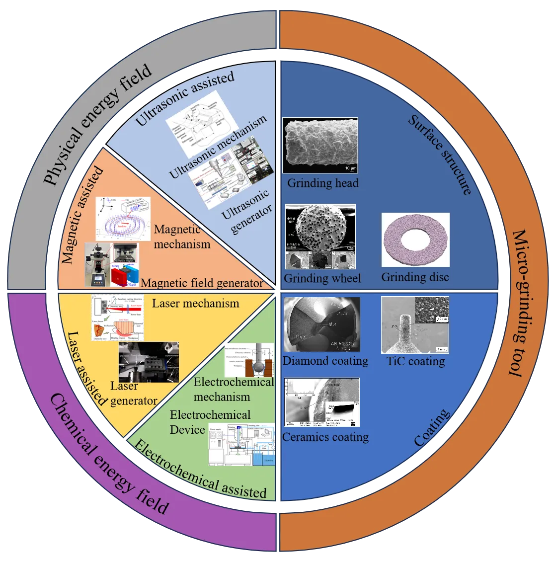
As shown in , this paper focuses on introducing the research progress of energy field-assisted grinding for hard, brittle and difficult-to-machine materials, and systematically expounds the research status and development trends in related fields. Firstly, the types and selection of grinding tools are introduced in detail to enable a clear understanding of the processing procedure. Secondly, the in-depth research on the mechanisms, devices, and performance of various energy field-assisted technologies, including ultrasonic field-assisted, laser-assisted, magnetic field-assisted, and electrochemical-assisted grinding, are discussed. The latest achievements in the material removal mechanism, parameter optimization, and processing quality during the energy field-assisted grinding process are introduced. Next, the challenges and solutions currently faced by energy field-assisted grinding technology are discussed, providing ideas and directions for research and development in this field. Finally, the future development trend of energy field-assisted grinding technology for hard, brittle, and difficult-to-machine materials are explored. Through this review, we hope to comprehensively showcase the research progress and development trends in the field of energy field-assisted grinding for hard, brittle, and difficult-to-machine materials, promote the continuous innovation and application of this technology, and drive the development of related industries.
. Tools and physical-chemical coupling energy fields for energy field-assisted grinding.
To achieve high-precision, high-quality and low-damage processing of brittle, hard and difficult-to-machine materials, different types of grinding tools have been developed. These grinding tools are usually designed and manufactured at the micro or even nanometer scale [
16]. Compared with traditional grinding processing, they have the characteristics of smaller size and higher precision, and can precisely remove the workpiece, thereby changing or shaping specific microstructure or three-dimensional (3D) tiny parts [
17]. The following section will introduce it in two aspects: surface structure and coatings [
18], aiming to better discuss the processing procedures and select suitable grinding tools for efficient processing.
2.1. Grinding Tools with Microstructures
Different surface structures are naturally applied in different processing scenarios. Common surface structure grinding tools are classified into wheel-type, head-type, discs, and handle type grinding tools [
19]. Among them, grinding wheel type and grinding head type grinding tools are used most frequently [
20]. The wheel-type grinding tools can be further classified into flat and cup-shaped grinding wheels according to their overall shape [
21]. Another commonly used type of grinding tool can be classified into cylindrical, spherical, and conical grinding heads, based on their overall shape. Head-type grinding tools are made by bonding a large number of small abrasive particles together with adhesives [
22]. Due to the rotational movement of the grinding head or the relative movement, abrasive particles penetrate into the workpiece like micro-cutting tools. Once the pressure exceeds the yield strength of the substrate, the material begins to undergo plastic deformation or breakage. As the grinding head keeps moving forward, the abrasive grains further shear the material, causing the material to separate from the workpiece in the form of fragments [
23]. In this way, the material is removed, and the micro-cutting process is successfully completed. The overall interaction between the grinding head and workpiece is reflected through the change of grinding force during the grinding process. These changes have an impact on multiple aspects, including brittle-plastic deformation, processing accuracy, surface quality of the workpiece, and the durability of the cutting tool throughout the entire grinding system [
24].
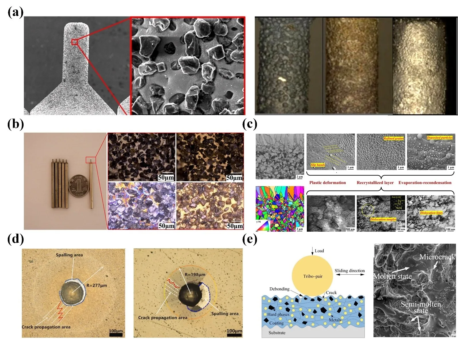
As shown in a, to explore the grinding behavior of electroplated diamond grinding wheels during the high-speed grinding of silicon nitride, Hwang et al. [
25] described the relationship between the morphology of grinding wheels and grinding behaviors such as grinding force, specific grinding energy, and surface roughness. The protrusion height of the abrasive grains of the grinding wheel follows a normal distribution, which serves as the benchmark for analyzing the subsequent wear process. The alumina abrasive grains used in the simulation test are shown in b, Rypina et al. [
26] investigated the influence of different abrasive geometries on the micro-cutting process of alumina. It was found that the geometric features of the abrasive grains and their orientation in the cutting direction would significantly affect the material removal process and the surface morphology. Wang et al. [
27] analyzed the morphology of the particle distribution on the grinding wheel before and after vibration, as shown in c. The simulation results provide crucial visual support for the conclusion regarding the relationship between the distribution of grinding wheel grains and the surface morphology. Wang et al. [
28] investigated the influence of material structure on the machinability of spinel-fixed abrasive grinding, and established the mapping relationship between the atomic percentage of grinding debris and aluminum element (d). Arrabiyeh et al. [
29] fabricated a fully micro-textured surface on hard and brittle materials with a micro-grinding tool, whose wear states under different parameters are shown in e. Surface microstructure is crucial for improving cutting performance and extending tool life. Pratap et al. [
30] carried out micro-texturing on the micro-grinding tool. By reducing the contact length with the workpiece, grinding force, and heat generation, the micro-texture was intermittently cut. The manufacturing steps of the unprocessed and different types (T1, T2, T3, T4, T5) of textured tools are shown in f. Among these, the commercial standard tool without texture treatment (T1) is used as the comparison benchmark. A microcavity at the center of the end face in T2, designed to reduce material dragging and stagnation at the zero cutting speed position at the tool center. A microgroove along the diameter of the end face in T3, which can improve the flow pattern of micro-chips and provide two passive zones around the tool periphery. T4 has two mutually perpendicular micro grooves designed, thus forming four passive zones around the tool. T5 has four intersecting micro grooves designed, forming eight passive zones around the tool, with the lowest intermittent ratio and contact area ratio.
In addition, the processing effect of microstructures on micro-grinding tools depends on factors such as the materials of the grinding tool and workpiece, the material being processed, shape and size, and grinding parameters. Wang et al. [
31] investigated the influence of carbon concentration gradient in the 20CrMnTi carburized steel gears after grinding with WD-201 microcrystalline corundum grinding wheels on microhardness, retained austenite,
etc., which verified the burn control ability of the grinding wheel in oil-based grinding fluid, and revealed the role of its fine crystal structure in reducing surface defects. Ren et al. [
32] analyzed the influence of different parameters on grinding quality. The feed rate is directly related to the chipping width and grinding quality. Moreover, when operating at a lower feed rate, a smaller chipping width and better grinding quality can be achieved. As the spindle speed increases, the surface roughness decreases slightly. Meanwhile, Shihab et al. [
33] proposed a method for optimizing process parameters through the analysis of the grey correlation degree matrix. It was found that the feed rate has the greatest influence on the average roughness and microhardness. The combination that generates the maximum grey correlation degree value is a cutting speed of 175 m/min, a feed rate of 0.1 mm/rev, and a cutting depth of 1 mm. Based on the proposed grey system theory, Singh et al. [
34] determined the optimal processing parameter combination through a hybrid optimization technique combining grey relational and principal component analysis. It was found that when the combined voltage is 16 V, the electrolyte concentration is 45 g/L, and the tool feed rate is 0.3 mm/min, the material removal rate is increased to 20.867 mm
3/min, outperforming other experimental combinations.
Therefore, the latest application of advanced preparation technology would undoubtedly bring new opportunities for the manufacturing of surface-structured micro-grinding tools. Specifically, 3D printing, laser processing, and chemical vapor deposition technology can achieve rapid manufacturing and high-precision processing of complex-shaped grinding tools. This, in turn, can significantly improve the performance and quality of these grinding tools. In addition, the development of intelligent grinding tools has become a prominent trend, with its core being the dynamic optimization of the processing process through adaptive grinding technology. The methods include real-time acquisition of grinding force, spindle power, and wheel wear data through multi-sensor fusion, and dynamic optimization driven by intelligent algorithms. This includes model-based control strategies that adjust the feed rate based on real-time grinding force to achieve improved accuracy and efficiency. Moreover, machine learning is also adopted, enabling intelligent numerical control systems to control leading errors within the micrometer range. Multi-modal control strategies integrate process adaptation, model adaptation and intelligent adaptation. In summary, all these advancements can comprehensively enhance processing efficiency and quality.
. (<b>a</b>) Schematic diagrams of the single-layer electroplated wheels of the new wheel and worn wheel, as well as scanning electron microscope micrographs of the fragments [
25]. (<b>b</b>) Geometric shapes of the abrasive grains used in the simulation [
26]. (<b>c</b>) Geometric models of two types of alumina abrasive grains [
35]. (<b>c</b>) The initial abrasive grain distribution and final surface morphology on the of the grinding wheel [
27]. (<b>d</b>) The energy spectrum analysis results of the grinding debris, including the atomic percentage and the distribution map of aluminum elements [
28]. (<b>e</b>) Post-processing images of micro-grinding tools and processing structures under different parameter combinations [
29]. (<b>f</b>) Design and manufacturing steps with different types of textured tools [
30].
In the ultra-precision grinding of hard and brittle materials, an extremely thin layer of functional coating is usually deposited on the surface of grinding tools via specific process technologies, to improve its hardness, wear resistance, corrosion resistance,
etc. Common coating materials for micro-grinding tools include metal coatings (such as titanium, chromium,
etc.), ceramic coatings (including alumina, zirconia,
etc.), and carbon-based coatings (such as diamond-like carbon coatings,
etc.), each of these has unique performance features [
35]. Ceramic coatings can effectively withstand the high temperature and stress generated when grinding hard and brittle materials, thereby extending the service life of grinding tools [
36]. Metal coatings usually have a certain degree of hardness and toughness, enabling them to withstand impacts and wear that occur during the grinding process [
37]. Carbon-based coatings possess high hardness and excellent chemical stability, demonstrating outstanding performance in harsh processing environments. All of these coatings on grinding tools can reduce surface roughness and enhance the processing quality of the machined workpiece. Wen et al. [
36] compared the cubic boron nitride coated micro-grinding tools to diamond-coated micro-grinding tools with the same particle size. The microscopic morphology of the TiC coated tool surface after micro-abrasive jet treatment is shown in a, it was found that the diamond-coated micro-grinding tools have better surface quality and are more suitable for grinding hard and brittle materials. To improve the grinding performance and service life of micro-grinding tools, Wang et al. [
37] prepared hydrogenated diamond-like carbon coating, siliconized diamond-like and TiC coated micro-grinding tools by optimizing the sputtering coating process, and revealed the influence on the surface quality of the workpiece machined by different coated micro-grinding tools, as shown in b. To enhance the high-temperature oxidation resistance of the coating, Qian [
38] adopted the femtosecond laser cladding technology with high-frequency pulse to remelt the material and reduce the surface roughness of the MCrAlY coating (c). The iron-based amorphous composite coating includes the original cladding layer and the coating after remelting treatment, reflecting the influence of the laser cladding process on the surface morphology.
. (<strong>a</strong>) Surface morphology of abrasive grains on TiC coated micro-grinding tools [<a href="#B36" class="html-bibr">36</a>]. (<strong>b</strong>) Micro-grinding tools with hydrogenated diamond-like carbon coating, siliconized diamond-like and TiC coatings prepared by vacuum sputtering coating technology [<a href="#B37" class="html-bibr">37</a>]. (<strong>c</strong>) Laser cladding of the MCrAlY coating [<a href="#B38" class="html-bibr">38</a>]. (<strong>d</strong>) Surface morphology after indentation test on diamond coatings [<a href="#B39" class="html-bibr">39</a>]. (<strong>e</strong>) High-speed arc spraying of FeNiCrAl-B<sub>4</sub>C-TiB<sub>2</sub> composite coatings and the schematic diagram of the friction process [<a href="#B40" class="html-bibr">40</a>].
As shown in
d, Yan [
39] deposited diamond coatings on cemented carbide tools to enhance grinding performance, and the diamond coatings of different structures could improve wear resistance and extend their service life. Indentation experiments on mixed-structured coatings with varying CH
4 contents under a 588-N load verified the rationality of multilayer micro-nanocrystalline diamond coating from the perspective of mechanical properties. Zhu et al. [
40] deposited FeNiCrAl-B
4C and FeNiCrAl-B
4C-TiB
2 coatings on the Q235 steel substrate by using high-speed arc spraying technology (
e). The two iron-based coatings present similar layered structures, and the main wear mechanism of the FeNiCrAl-B
4C-TiB
2 coating is brittle fracture. Abhishek et al. [
41] analyzed the performance of dry micro-abrasive sandblasting technology by observing the morphology of the surface coating. It was found that when using single-layer electroplated cubic borax nitride (CBN) grinding wheels for contour grinding of nickel-based superalloys, the grinding energy generated is relatively low. Yao et al. [
42] ground Aermet100 ultra-high strength steel using resin-bonded white alumina (WA) grinding wheels and cubic boron nitride (CBN) grinding wheels, and found that the grinding temperature had a greater impact on residual stress. When the grinding rate was high, tensile stress was prone to occur on the surface, and the depth of the residual stress layer increased with the temperature rise. The influence layer thickness of the CBN grinding wheel was smaller and was mainly dominated by the grinding force. For the WA grinding wheel, it was mainly dominated by grinding temperature, and the depth of the softening layer increased with the rise in temperature. Oztrk et al. [
43] compared copper-based and iron-based corundum grinding wheels with surface microstructures and found that the service life of iron-based corundum tools was relatively longer. Ociepa et al. [
44] studied the condition of finishing high carbon steel with low-content polycrystalline CBN grinding tools and determined that the optimal state was a feed rate of 0.3 mm/rev. Huang et al. [
45] characterized the surface coating and microstructure of polycrystalline CBN abrasive particles by using the Voronoi diagram theory. The CBN particles and crack branches would affect the size distribution and the overall toughness of abrasives. Shi et al. [
46] explored the influence of heat treatment on microcrystalline adhesives of CBN grinding tools. Different heat treatment processes mainly change the contents of LiALSi
2O and LiAlSiCO
2 in the microcrystalline adhesives. This, in turn, led to changes in the coefficient of thermal expansion (CTE) of the adhesive and had an impact on the bending strength of CBN grinding tools with microcrystalline adhesives.
In summary, the selection of coatings should consider factors such as the material properties of the workpiece, process requirements, and the environment, as well as the compatibility between the coating and the grinding tools. However, maintaining sufficient bonding strength between the coating and the substrate remains a key issue. When the bonding force is not strong enough, the coating is prone to peeling off during the grinding process, which will reduce the service life of grinding tools. Furthermore, when preparing micro-grinding tools, 3D printing technology can quickly form complex structures and achieve lightweight design, but its material selection is limited. Laser processing can achieve sub-micron high-precision cutting or surface texture modification, but thermal influence can easily cause material deformation. Chemical vapor deposition (CVD) greatly improves the wear resistance and chemical stability through super-hard coatings, but the process temperature limits the selection of substrates, and the deposition rate is relatively slow. These preparation technologies need to be selected based on specific requirements such as precision, complexity, and durability.
Traditional grinding processes often fail to meet the manufacturing requirements of precision components in terms of processing accuracy and high quality in some high-tech fields such as aerospace, electronic information, and biomedicine. Moreover, with the increase demand for hard, brittle, and difficult-to-machine materials, the introduction of energy fields for auxiliary grinding is of great significance. However, as an emerging technology, it still faces difficulties to varying degrees in many aspects [
3].
- (1)
-
Precise regulation of energy field parameters. Energy field-assisted grinding involves various parameters, including laser power, pulse frequency, spot size within the laser field, as well as magnetic field intensity and direction etc. These parameters interact with each other and have a complex coupling relationship with the process parameters of grinding. To precisely control these parameters and achieve the expected processing effect, a large number of experiments and detailed data analysis are indispensable.
- (2)
-
Monitoring and evaluation of energy field effects. The microscopic mechanism of material removal under the influence of the energy field is rather complex. It requires numerous physical, chemical, and other changes, and it is difficult to understand it relying only on a single measurement method fully. On the other hand, at present, there is still a lack of an effective and comprehensive evaluation index system to measure the overall impact of energy field-assisted grinding. The existing traditional indicators such as surface roughness and material removal rate, often fail to fully reflect the profound impacts brought by the energy field, such as improving processing accuracy and quality. This situation is not benefit to the further optimization of the energy field-assisted grinding process.
3.1. Physical Energy Field-Assisted Grinding
The implication of physical energy field-assisted grinding in hard and brittle materials depends on various unique physical effects. Aiming to alter the interaction between abrasive particles and the workpiece, and improve the influence of the physical state of the material. Through these manners, the grinding effect and processing quality can be improved. Physical energy field-assisted grinding requires the transfer and conversion of different forms of energy within the machining system. For example, in an ultrasonic field, electrical energy is converted into high-frequency mechanical vibration energy via an ultrasonic transducer. Once physical energies are transferred to the grinding area, they will interact with the abrasive particles and the workpiece, thereby changing the traditional grinding mode that relies solely on mechanical grinding force.
3.1.1. Mechanism
Ultrasonic-assisted grinding is a composite processing technology that ingeniously combines ultrasonic vibration with traditional grinding methods. During this process, high-frequency electrical signals are converted into high-frequency mechanical vibrations by ultrasonic transducers and then amplified by amplitude rods before being transmitted to the grinding tool. Under the influence of ultrasonic vibration, abrasive particles adhering to grinding tools will repeatedly impact and rub against the surface of hard and brittle materials at high speed. This dynamic interaction can effectively remove materials, therby enabling the processing of hard and brittle materials that are usually difficult to handle only through traditional grinding.
Usually, high-frequency vibration is generated in a single direction, such as the axial or radial direction of grinding wheel. During the cutting process of the workpiece, the abrasive particles only have additional motion caused by the vibration in that specific direction. This is one-dimensional (1D) ultrasonic vibration-assisted grinding [
4], and the ultrasonic vibration is simultaneously applied to the grinding tool or workpiece in two mutually perpendicular directions. If one direction can be along the feed direction of grinding and the other direction can be perpendicular to the surface of the workpiece, it namely two-dimensional (2D) ultrasonic vibration-assisted grinding [
8]. At this time, the cutting trajectory of abrasive particles becomes complex and diverse. Compared with 1D ultrasonic vibration, this method can further improve surface quality, accuracy and material removal efficiency. Meanwhile, the three-dimensional (3D) ultrasonic vibration-assisted grinding includes the feed direction during the grinding process, the direction perpendicular to the workpiece, and another lateral direction perpendicular to the first two directions. In 3D space, the cutting trajectory of abrasive particles presents an extremely complex form, featuring high dynamics, intermittence and irregularity. Ding et al. [
47] analyzed the kinematics of a single diamond grain by considering the influence of the compound grinding system and trajectory, and the 3D ultrasonic-assisted grinding highly reduced the surface roughness compared with 2D ultrasonic-assisted grinding.
In addition, processing parameters have a significant impact on the performance of ultrasound-assisted grinding. Li et al. [
48] analyzed the influence of vibration direction on grinding characteristics and surface morphology through the simulation of abrasive motion. The processing results under different amplitudes show that as the amplitudes of the workpiece and tool increase, the normal force in the grinding force decreases at a faster rate than the tangential force. Wen et al. [
49] proposed that when the ultrasonic amplitude is 4 μm, the surface contact performance of the workpiece is the best. At this time, the surface roughness of the processed workpiece is reduced by ~24% compared to the conventional grinding surface. Under the same load, the contact stiffness of the ultrasonic-assisted grinding surface is increased by at least 68%, and the maximum local contact pressure is reduced by ~17%. Abdollahi et al. [
50] found that the vibration amplitude has the most significant effect on improving the material removal rate and enhancing the thickness of the recast layer. The optimal parameters, that is, the vibration amplitude of 40 μm, the modulation frequency of 1200 Hz, and the gas pressure of 0.25 MPa, a material removal rate of 2.0 m
3/min, are optimized with the response surface method.
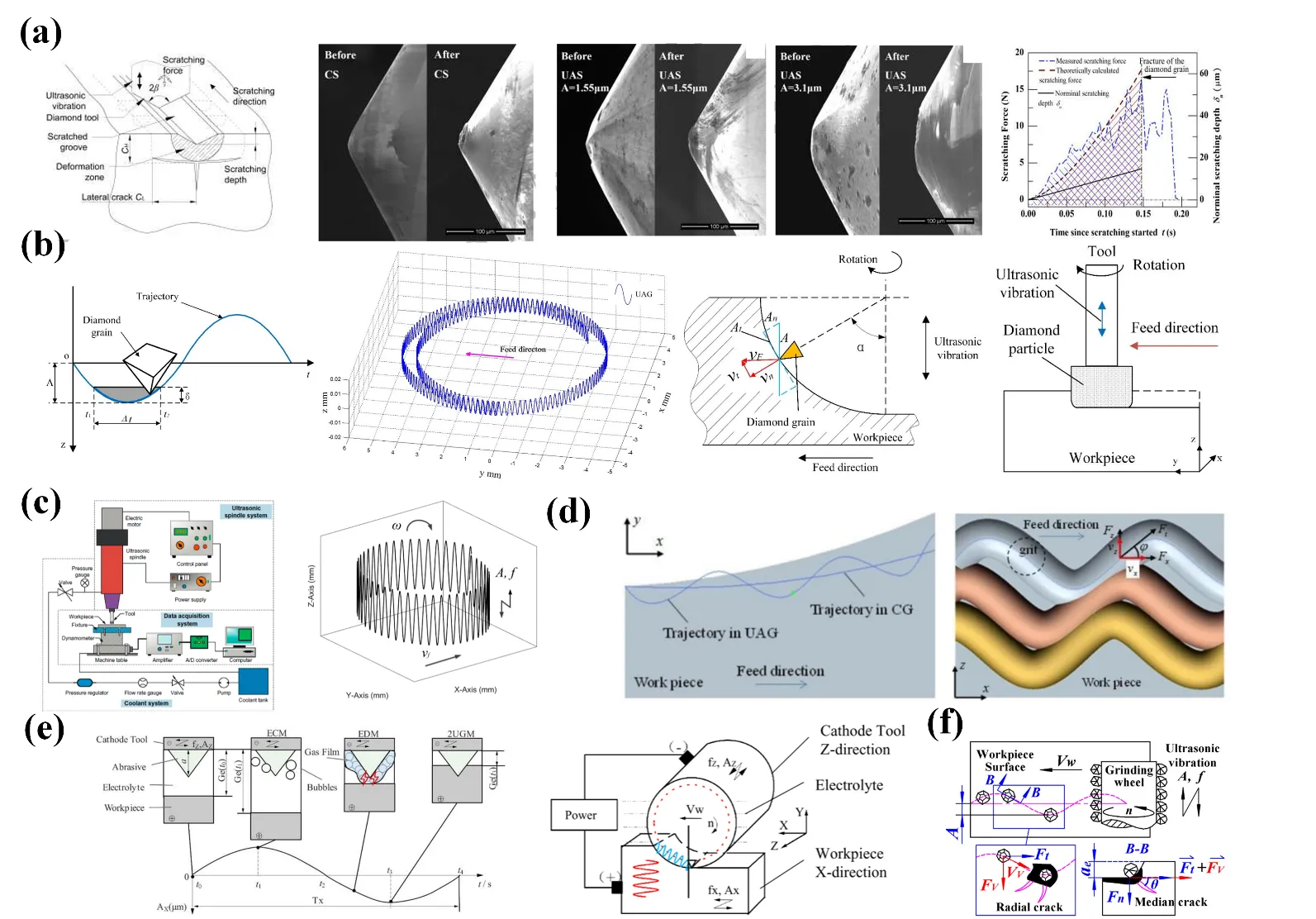
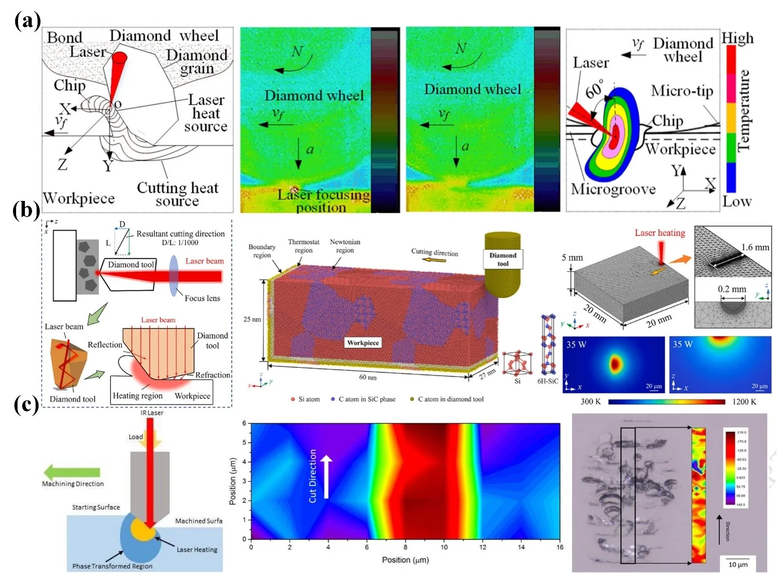
Taking the single-particle cutting behavior during ultrasonic-assisted grinding of hard and brittle materials as the research object, Zheng et al. [
51] proposed to establish an ultrasonic-assisted scratch model and explained the variation law of related mechanical parameters, as shown in
a. To predict the cutting force during the ultrasonic-assisted grinding process of hard and brittle materials, Kang et al. [
52] established a cutting force model considering the influence of diamond abrasive grains on the transition fillet of grinding tool (
b). To evaluate the influence of process parameters on the surface quality of ultrasonic-assisted end-face grinding of SiCp/Al composites, Zheng et al. [
53] conducted a single-factor experiment in an ultrasonic vibration machining center and found that the 3D surface fractal dimension increased nonlinearly with the spindle speed and amplitude and decreased with the increase of feed rate and cutting depth. The grinding schematic diagram and abrasive grain trajectory are shown in
c. This method is suitable for processing workpieces with complex shapes, such as molds for components in the aerospace field. For instance, when processing aircraft engine blades with spatially distorted surfaces, 3D ultrasonic vibration-assisted grinding enables abrasive particles to fully utilize ultrasonic vibration in all directions, which can better ensure high precision and good surface quality of the blade surface, and meet the processing requirements of complex-shaped workpieces in various positions.
Chen et al. [
54] studied the changes in surface roughness during ultrasound-assisted dry grinding of 12Cr2Ni4A steel with large-diameter grinding wheels. According to the Kinematic characteristics, feed depth and speed have a significant influence on ultrasound-assisted grinding. Furthermore, due to the Poisson effect, the ultrasound-assisted dry grinding of large-diameter grinding wheels is a combination of axial and radial ultrasound-assisted grinding. Radial vibration improves surface roughness by deepening individual grinding trajectories, while axial vibration smooths the surface topography by increasing the interaction and overlap of adjacent cutting trajectories, as shown in
d. To study the influence of the vibration direction on the processing effect of SiCp/Al composites, Li et al. [
48] proposed the ultrasound-assisted grinding-electrolysis-electrical discharge machining technology. The workpiece is removed through electrolytic dissolution, grinding, and discharge corrosion. The surface became smoother through tangential grinding and electrolytic-electrical discharge machining, resulting in a reduction of grinding force and surface roughness, as shown in
e. Therefore, controlling the ultrasonic frequency properly can play an auxiliary role in grinding and is expected to achieve high-quality and high-precision processing [
55].
. (<strong>a</strong>) Schematic diagram of material removal in the ultrasonic-assisted scratch process [<a href="#B51" class="html-bibr">51</a>]. (<strong>b</strong>) Movement trajectory of a single abrasive grain during the ultrasonic-assisted grinding [<a href="#B52" class="html-bibr">52</a>]. (<strong>c</strong>) Schematic diagram of ultrasonic vibration-assisted end face grinding and the movement trajectory of abrasive grains [<a href="#B53" class="html-bibr">53</a>]. (<strong>d</strong>) Cutting movement trajectories in the <em>x</em>-<em>y</em> plane and <em>x</em>-<em>z</em> plane during ultrasonic-assisted grinding [<a href="#B54" class="html-bibr">54</a>]. (<strong>e</strong>) 2D ultrasonic-assisted machining mechanism of ultrasound-assisted grinding-electrolysis-electrical discharge machining [<a href="#B48" class="html-bibr">48</a>]. (<strong>f</strong>) The movement and force conditions of abrasive grains during axial ultrasonic vibration-assisted cylindrical grinding [<a href="#B56" class="html-bibr">56</a>].
Selecting the appropriate ultrasound-assisted grinding method provides a theoretical basis for the high-precision processing of hard and brittle materials. Sun et al. [
56] conducted a theoretical analysis to establish the kinematic function of a single abrasive grain (
f) and collected data such as grinding force and surface roughness. It has been found that axial ultrasonic vibration can increase the dynamic contact length and reduce the thickness of grinding chips. Xiang et al. [
57] suggested that the ultrasonic-assisted grinding significantly changes the movement characteristics of abrasive grains during ordinary cylindrical processing. The trajectory of abrasive grain movement becomes longer, the grinding efficiency increases, and the surface quality of the workpiece is significantly improved. By establishing a kinematic function model, it is found that under the same material removal rate, Ultrasonic vibration-assisted grinding enhances material removal rate, reduces surface roughness, and minimizes damage by superimposing high-frequency and micro-amplitude ultrasonic vibrations [
58]. Yang et al. [
59] established the contact rate model during intermittent machining based on the kinematic analysis of ultrasonic vibration-assisted grinding. The motion trajectory of ultrasonic vibration-assisted grinding is longer than that of ordinary grinding, which is helpful for improving the surface quality of certain aviation materials [
60]. Frank et al. [
61] analyzed the kinematics of meshing between grains and workpieces through single-grain scratch tests. When ultrasonic vibration is superimposed on the grinding process, the material removal amount of each grain is increased, and the impact effect of ultrasound-assisted grinding would cause fragmentation around the generated scratches. Chen et al. [
54] revealed that ultrasound-assisted dry grinding can reduce the negative impact of cutting fluid on the environment and improve the surface quality of the machined object. Mao et al. [
62] improved the performance of the grinding wheel by altering the structure of the working surface, allowing the coolant to enter the grinding area for effective lubrication. When using CBN grinding wheels for ultrasound-assisted dry grinding of 12Cr2Ni4A steel, the surface roughness can be reduced by 30% compared with ordinary dry grinding. Moreover, the physical effects of ultrasound-assisted grinding are often combined with other processing methods, such as plasma electrolytic oxidation technology,
etc., all of which have achieved favorable results [
63].
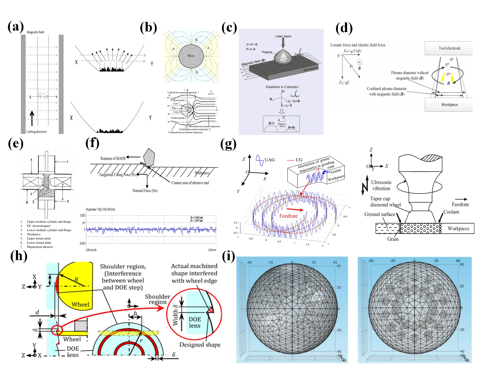
Magnetic field is another important physical-assisted grinding method. During the processing, a magnetic field is applied to the working area. Material removal can be achieved by taking advantage of the specific distribution and movement patterns formed by abrasive particles under the influence of a magnetic field. Magnetic abrasive particles are subjected to magnetic force, causing them to aggregate, arrange and present chain or brush-like structures. Then, these abrasive particles come into contact with the workpiece, under the combined action of grinding force and magnetic force, to cut, scrape and squeeze the workpiece, thereby effectively removing the material. Among numerous experiments, magnetic field assistance is often used as a means to optimize processing properties rather than directly participating in cutting operations. Of course, the role of the physical energy field in the micro-grinding of hard and brittle materials cannot be ignored. Zhang et al. [
64] used magnetic field-assisted technology to reduce energy consumption and thermal deformation in wire electrical discharge machining to improve processing performance and reduce energy consumption and thermal deformation. In the optical instrument manufacturing industry, the demand for optical components in astronomical telescopes is constantly increasing. Because in a space with an extremely large temperature difference, the diffraction lens is very sensitive to reducing chromatic aberration caused by thermal expansion. To solve this problem and achieve the fine processing of synthetic silica lenses, Suzuki et al. [
65] proposed a magnetic-assisted polishing method. The optical lenses were grounded using sharp-edge diamond grinding wheels, and then the shape deviation and changes in surface roughness were evaluated through grinding and polishing tests.
During the ultrasonic vibration and magnetic field-assisted diamond composite cutting of titanium alloys, Deng et al. [
66] discovered that the magnetic field could suppress the surface ripples and unevenness caused by material recovery during ultrasonic assisted diamond cutting of titanium alloys, as shown in
a. Through theoretical modeling and experimental verification of the movement trajectory of magnetic abrasive grains, Peng et al. [
67] proposed a method for abrasive wire-saw in a magnetic field was proposed. The magnetic field environment and the different movement trajectories of magnetic abrasive grains in the magnetic field are shown in
b. Ye et al. [
68] found that the magnetic field-assisted laser drilling process can produce a deeper drilling depth, and generate confined plasma plumes and relatively less residue, as shown in
c.
To clarify the differences in magnetic fields during the processing of different materials, Ming et al. [
69] took the magnetic material SKD11 and the non-magnetic material Ti6Al4V as workpieces, and conducted a series of electrical discharge machining experiments with different magnetic intensities and servo voltages. When the magnetic intensity increases, the energy of the discharge channel becomes more concentrated, so as to improve the energy utilization efficiency and material removal rate. Because the debris of the magnetic material is more likely to be discharged from the discharge gap under the action of the magnetic field, as shown in
d. Singh et al. [
70] optimized the process parameters to achieve offline monitoring in the magnetic field-assisted abrasive flow machining process. The experimental device system is shown in
e. Kanish et al. [
71] investigated the key parameters of magnetic field-assisted abrasive finishing based on the Taguchi orthogonal array, including the electromagnetic voltage, machining clearance, electromagnet speed, abrasive size, and feed rate. The contact situation of the magnetic abrasive brush with the workpiece is shown in
f. Ding et al. [
72] conducted comparative experiments using brazed grinding wheels with specific grain distribution to explore the material removal mechanism of ultrasound-assisted grinding of SiC ceramics (
g). As the thickness of the undeformed chips increased, the material removal mechanism changed from ductile removal to brittle fracture. Suzuki et al. [
65] utilized the magnetic field-assisted polishing method to precisely process the silica diffraction lens, visually presenting the geometric interference problem existing when grinding convex lenses, as shown in
h. Zhao et al. proposed the magnetic-assisted ultra-precision grinding technology for processing nickel-based alloys, which can directly suppress the vibration of the grinding wheel by utilizing the magnetic field [
73]. In
i, Tang et al. [
74] investigated the auxiliary processing effect of the magnetic field through the meshing of periodic and concentrated magnetic fields. Du et al. [
75] explored the evolution mechanism of the solidification structure and the changes in mechanical properties during the selective laser melting process of AlSi10Mg alloy under a static magnetic field. A static magnetic field could lead to a reduction in the dendrite spacing in the molten pool, refine the grains and improve the mechanical properties. Cui et al. [
76] reported the frictional performance of graphene nanofluid lubricants at the interface between grinding wheels and workpieces, providing a basis for the collaborative optimization of processing parameters and lubrication conditions in magnetic field-assisted grinding.
According to the above research, it can be evident that ultrasonic assistance can effectively reduce grinding force, optimize the material removal mechanism, and thus make the grinding process more stable and efficient. Meanwhile, the magnetic field assistance can regulate the movement trajectory of abrasive grains, further improving the stability and accuracy of the grinding operation. These physical effect energy field-assisted methods have successfully solved problems such as microcracking and precision control during the grinding process of hard and brittle materials.
. (<strong>a</strong>) The variation of parameters such as electrode gap, current density and pressure within one vibration cycle [<a href="#B66" class="html-bibr">66</a>]. (<strong>b</strong>) The distribution of the magnetic field around the wire and the movement of magnetic abrasive particles in the magnetic field [<a href="#B67" class="html-bibr">67</a>]. (<strong>c</strong>) The confinement effect of the magnetic field on laser-induced plasma [<a href="#B68" class="html-bibr">68</a>]. (<strong>d</strong>) The influence of the magnetic field on the processing of silicon [<a href="#B69" class="html-bibr">69</a>]. (<strong>e</strong>) Schematic diagram of the offline monitoring [<a href="#B70" class="html-bibr">70</a>]. (<strong>f</strong>) Contact situation of the magnetic abrasive with the workpiece [<a href="#B71" class="html-bibr">71</a>]. (<strong>g</strong>) Overlap of abrasive grain trajectories in ultrasound-assisted grinding [<a href="#B72" class="html-bibr">72</a>]. (<strong>h</strong>) Interference area between the edge of the grinding wheel and the steps [<a href="#B65" class="html-bibr">65</a>]. (<strong>i</strong>) Meshing situation of periodic magnetic field and concentrated magnetic field [<a href="#B74" class="html-bibr">74</a>].
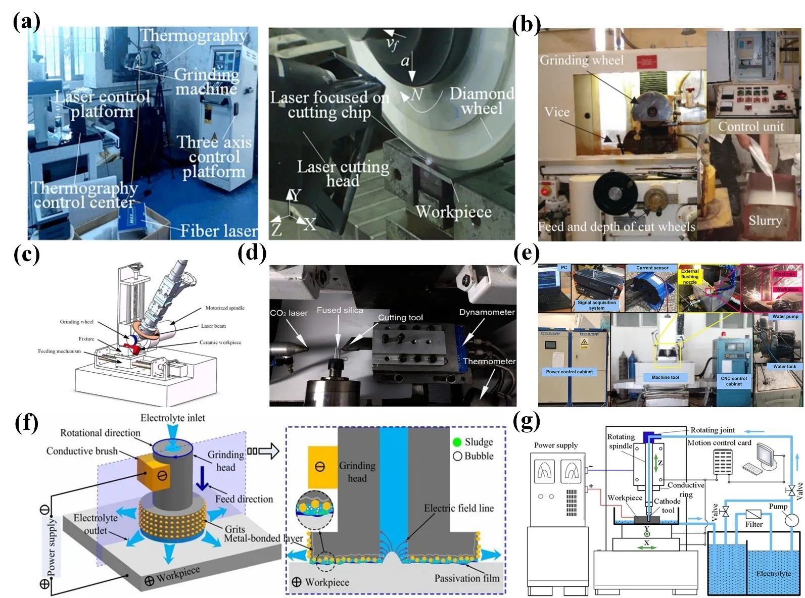
3.1.2. Devices and Performance
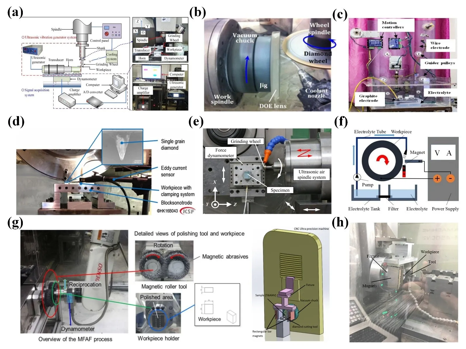
Most of the experiments on ultrasound-assisted grinding are conducted on CNC machines. Yang et al. [
59] carried out grinding tests on CNC lathes and used ceramic-bonded CBN grinding heads. The device diagram is shown in
a. Wu et al. suggested that the grinding force and surface roughness decrease with the increase of spindle speed and ultrasonic amplitude, but increase with the increase of feed rate and cutting depth in ultrasonic vibration-assisted grinding [
77]. Suzuki et al. [
65] conducted different magnetic field-assisted grinding experiments, the differences in their devices mainly lie in the magnetic field generation devices, except for the common electromagnetic coils and permanent magnets, as shown in
b. The ultrasound-assisted grinding device adopted by Rattan et al. [
78] mainly consists of a processing chamber, electrode wire, workpiece feed unit and DC power supply, and uses neodymium iron boron disc permanent magnets. A brass wire with a diameter of 100 μm is used as the tool electrode (cathode), and a graphite wire with a diameter of 20 mm is used as the circular counter electrode (anode). The experimental setup is depicted in
c.
Heike et al. [
61] adopted an ultrasonic generator that regarded as specially designed plate with multiple resonant frequency responses, which could vibrate workpieces of different sizes and weights during the grinding process (
d). Li et al. analyzed the potential formation mechanisms of surface integrity under different ultrasonic-assisted grinding proceses and found that the abrasive particles have spatial movement trajectories and a gradually increasing cutting depth [
79]. In addition to CNC machine tools, there are also cases where ultrasonic vibration processing is carried out on precision grinding machines, as shown in
e. Sun et al. [
56] equipped the precision grinding machine with an ultrasonic vibration air spindle system, which generates axial ultrasonic vibration by the spindle vibrator and applies it to the grinding wheel. Wang et al. [
80] provided the magnetic field by an external Nd-Fe-B permanent magnet that was directly placed below the machining gap to assist in electrochemical machining (
f) As shown in
g, the design by wang et al. [
81] can present different magnetic flux densities at different target positions around the roller, enabling the magnetic abrasive to generate a reorganization mechanism each time. Khali et al. [
82] used a composition of four neodymium magnets, which were fixed on a custom steel frame to generate a magnetic field in the grinding experiment, as shown in
h.
. (<strong>a</strong>) Experimental device for ultrasonic vibration-assisted grinding [<a href="#B59" class="html-bibr">59</a>]. (<strong>b</strong>) Basic components of the experimental device such as grinding wheels and workpieces [<a href="#B73" class="html-bibr">73</a>]. (<strong>c</strong>) The magnetic field-assisted grinding device includes a processing chamber, electrode wire and DC power supply [<a href="#B78" class="html-bibr">78</a>]. (<strong>d</strong>) The experimental device for single-particle scratch testing including ultrasonic units and single-particle diamonds [<a href="#B61" class="html-bibr">61</a>]. (<strong>e</strong>) The grinding experiment system consists of precision grinding machines, ultrasonic vibration air spindle systems, force gauges, and grinding wheels [<a href="#B58" class="html-bibr">58</a>]. (<strong>f</strong>) Schematic diagram of cylindrical precision polishing machine tools with the electrolyte tube, magnet, pump, and filter [<a href="#B80" class="html-bibr">80</a>]. (<strong>g</strong>) The experimental setup mainly consists of a double magnetic roller tool, a 6-degree-of-freedom mechanical arm, and a dynamometer [<a href="#B81" class="html-bibr">81</a>]. (<strong>h</strong>). The experimental setup includes cutting tools, a magnetic field source and machine tools [<a href="#B82" class="html-bibr">82</a>].
When building the energy field-assisted grinding device, it is necessary to ensure that the structural design is reasonable and the energy field parameters are precisely regulated to meet the process requirements and stability. To address the issues of low energy conversion efficiency and heat generation in ultrasonic transducers, the industry typically employs a cooling structure combining thick copper electrode plates with compressed air to reduce temperature rise through forced convection. At the same time, a pre-stressed sleeve design is adopted to minimize energy loss caused by mechanical vibration [
79]. Yang et al. [
83] introduced different ultrasonic generators and auxiliary processing devices. The relationship among their ultrasonic frequencies, amplitudes, and contact times is shown in
a. Yang et al. [
77] performed the influence of amplitude on the grinding force of CNC lathes, as shown in
b. Xiang et al. [
57] studied the conditions of ultrasound-assisted high-speed grinding on a five-axis machining center. The motion characteristics, grinding force, surface quality of the workpiece, and abrasive wear of single-CBN abrasive grains. The worktable moves up and down to achieve tool feed, and the workpiece rotates at high speed through the machine tool spindle. The wear conditions of a single CBN abrasive grain after ultrasonic-assisted grinding and conventional grinding are depicted in
c. Intelligent and sustainable manufacturing systems provide more convenient tools for the processing of hard and brittle materials [
84]. Chen et al. [
85] adopted an improved CNC machining center and installed a specially designed ultrasonic vibration device to conduct 3D ultrasonic vibration-assisted grinding of zirconia ceramics (
d). Heike et al. [
79] conducted ultrasonic scratch experiments on plates with multiple resonant frequency responses. The influence of material accumulation and removal is shown in
e. Ming et al. [
69] constructed a magnetic field on the electrical discharge machining tool to process some complex-shaped and high-performance materials. The movement trajectory of the electron beam is demonstrated in
f. The main difference of the device developed by Suzuki et al. [
65] lies in the magnetic field generation device. The working principle and structure of the magnetic field-assisted polishing system on the four-axis (X, Y, Z, C) ultra-precision machine tool (
g).
. (<strong>a</strong>) Schematic diagram of tool-workpiece contact and cutting characteristics in ultrasonic vibration-assisted machining [<a href="#B83" class="html-bibr">83</a>]. (<strong>b</strong>) The influence of amplitude on grinding force in ultrasonic vibration-assisted grinding [<a href="#B77" class="html-bibr">77</a>]. (<strong>c</strong>) Two states of contact grinding and separation between a single abrasive grain and workpiece [<a href="#B57" class="html-bibr">57</a>]. (<strong>d</strong>) The 2D and 3D grinding force waveform diagram of ultrasonic vibration-assisted grinding [<a href="#B85" class="html-bibr">85</a>]. (<strong>e</strong>) Scratch profile during ultrasonic workpiece oscillation and the penetration depth of ultrasonic stimulation [<a href="#B79" class="html-bibr">79</a>]. (<strong>f</strong>) Simulation results of particle path on workpiece surface under conventional and ultrasonic assisted scratch conditions [<a href="#B69" class="html-bibr">69</a>]. (<strong>g</strong>) Single-particle scratch test experiment with ultrasonic unit and specific single-particle diamond [<a href="#B73" class="html-bibr">73</a>].
In summary, the device selected for magnetic field-assisted grinding experiments is based on the material, such as precision grinding machines, micro-nano abrasive grinding wheels, CNC machine tools,
etc. Most magnetic field generating devices have both magnetic field control and regulation capabilities, and are finally equipped with measurement and monitoring devices. At present, with the assistance of physical energy fields, there are several problems with the experimental devices of ultrasonic waves and magnetic fields. The energy conversion efficiency of ultrasonic transducers is rather limited. During high-energy output, unstable phenomena such as heating may occur. In the magnetic field experimental device, it is quite difficult to precisely control and rapidly adjust the magnetic field. Some devices for processing techniques that require dynamic changes in the magnetic field. At the same time, the magnetic field has a certain degree of interference with the surrounding equipment, which can affect the normal function of electronic components. Therefore, effective shielding measures need to be taken.
3.2. Chemical Energy Field-Assisted Grinding
Chemical energy field-assisted grinding shows significant advantages in the micro-grinding of hard, brittle, and difficult-to-machine materials. For instance, a magnetic field forms a flexible grinding tool through the magnetorheological effect, reducing the impact of abrasive grains on the workpiece. High-frequency vibration generates impact crushing and micro-forging effects, reducing the critical cutting force and minimizing the depth of subsurface damage and edge chipping. The laser field, with its high-energy beam, can precisely control the action area, efficiently and intensively process specific areas. At the same time, by altering the chemical properties of the material surface, it makes hard materials relatively fragile, thus enhancing grinding efficiency and reducing time costs. The electrochemical field, by gently and precisely controlling the chemical state of the material surface, enables it to reach the softened state before grinding, reducing grinding force and energy consumption. The combination of the two mechanisms makes chemical energy field-assisted grinding a highly promising method for micro-grinding of hard and brittle materials in industrial applications.
3.2.1. Mechanism
Hard and brittle materials are generally composed of specific chemical bonds, such as ionic and covalent bonds contained in ceramic materials. For laser-assisted grinding, when the laser is irradiated onto the surface of hard and brittle materials, its high energy density enables the materials to absorb photon energy. Once the photon energy reaches or exceeds the bond energy of the chemical bonds in the material, it will trigger the breaking of these chemical bonds. From a chemical perspective, this change in the chemical structure of the material makes the previously stable material have higher chemical activity in specific local areas, thus laying a solid foundation for the subsequent removal of the material. For instance, under laser irradiation, the chemical bonds within ceramic materials are broken, weakening the connections between atoms. Therefore, through mechanical means such as grinding, it becomes much easier to remove the materials in which these chemical bonds are activated in this way
Furthermore, for some composite hard and brittle materials, lasers can selectively act on specific chemical bonds of different components. This selective effect leads to obvious chemical structural changes among various components, which in turn helps to control the material removal process more precisely and effectively, and meet the requirements of microfabrication of hard and brittle materials. Meanwhile, in specific processing scenarios, chemical reagent gases can be deliberately introduced into the processing area. The high temperature generated by lasers can promote chemical reactions between these gases and hard and brittle materials, thereby generating new compounds. These newly formed compounds are either easier to remove during the subsequent grinding process or help improve the surface quality. If some compounds with lubricating properties are produced, this can effectively reduce the friction and material damage in the grinding process. When cutting silicon nitride, due to the large tool wear and cutting force, the surface integrity is poor, and the material removal rate is limited. Therefore, Bahman et al. [
86] proposed a laser-assisted grinding process to overcome the technical limitations existing in the grinding of silicon nitride. Wang et al. [
87] demonstrated that compared with conventional grinding processing, when laser-assisted processing of AL
2O
3P/Al composite materials, the cutting force and tool wear were reduced by 30–50% and 20–30%, respectively. Hu et al. [
88] proposed that laser-assisted dry micro-grinding aims to improve the surface quality of difficult-to-machine materials. The grinding model and the steady-state temperature distribution are shown in
a. Liu et al. [
89] studied the influence of laser-assisted processing on the processing mechanism of RB-SiC. The schematic diagram of the laser-assisted slotting experiment, the path of the laser beam in the diamond tool, and the molecular dynamics model of the RB-SiC nano-cutting simulation are depicted in
b. The subsurface damage mechanism is mainly manifested as the tool geometric parameters influencing the degree of damage by regulating the stress field, temperature field and phase transformation evolution.
. (<strong>a</strong>) Theory model of laser-assisted micro-grinding and its temperature distribution [<a href="#B88" class="html-bibr">88</a>]. (<strong>b</strong>) Schematic diagram of the laser scanning path in the diamond tool, the molecular dynamics (MD) model of RB-SiC and the simulation results of laser-induced temperature zone [<a href="#B89" class="html-bibr">89</a>]. (<strong>c</strong>) Schematic diagram of the laser-assisted processing of sapphire, and its stress map and surface morphology [<a href="#B90" class="html-bibr">90</a>].
To explore the role and mechanism of laser-assisted processing in reducing damage during the finishing process of sapphire surfaces, Langan et al. [
90] employed an universal micro-friction meter to process the sapphire crystals with different laser wavelengths and powers. Compared with the traditional single-point diamond turning, the surface damage of sapphire processed with laser assistance is greatly reduced, and the residual stress condition is improved. The higher laser power can effectively alleviate the problems of fracture, crack, and fragmentation, as shown in c. The parameters of laser processing include power, wavelength, pulse frequency, and scanning speed
etc. Among them, a higher laser power can cause the material to heat up and soften more quickly, but it is also prone to causing thermal damage. Fortunato et al. [
91] established a finite element model to analyze the thermal stress generated by laser irradiation and predict crack formation. At the same time, attention should also be paid to the influence brought by grinding parameters. Ma et al. [
92] found that when laser-assisted grinding alumina ceramics, the processing parameter that laser power has the greatest impact on surface roughness. The second key parameters are the grinding depth and the rotational speed of the grinding wheel. Therefore, the optimal surface roughness value can be obtained using appropriate processing parameters. Rashid et al. [
93] studied the processing states under different laser powers and concluded that the cutting force used for titanium alloys in laser-assisted processing was significantly reduced. Singh et al. [
94] investigated the changes in microstructure and microhardness of the heat-affected zone (HAZ) caused by different scanning speeds. A 3D transient finite element model of the moving laser heat source was developed to predict the temperature distribution in the workpiece. Commercial lasers can be classified into blue, green, and purple lasers based on their different laser wavelengths. Among them, green laser has been widely used in laser-assisted etching of silicon due to its ideal absorption effect [
95]. Ultraviolet lasers with shorter wavelengths can theoretically be better absorbed by metallic materials [
96], but currently there are few commercial applications in this regard. So far, laser-assisted processing technology for hard and brittle materials has only been attempted under laboratory conditions [
97]. Due to its inevitable thermal instability and relatively immature technology, its application is still limited. For instance, Song [
98] explored that the processing effect was not stable under different spindle speeds, feed rates, pulse duty cycles, and different grinding tools.
As for the electrochemical field, the method of removing materials by controlling electrochemical reactions is fundamentally different from mechanical materials removal relying on mechanical grinding. This method effectively avoids the physical damage that mechanical force may cause to the workpieces. For hard and brittle materials such as quartz and sapphire which are highly sensitive to processing stress, this is a gentle yet effective material removal method. During the electrochemical process, a passivation film forms on the workpiece. This is a dense oxide or other compound film formed by the chemical reactions of atoms on the surface under the conditions of electrolyte and potential. This passivation film exhibits stable chemical properties, preventing excessive dissolution of the material and thereby protecting the workpiece.
On the other hand, during the subsequent grinding process, when the abrasive particles come into contact with and remove this film, a new surface will be exposed. Subsequently, this newly exposed surface once again participates in the electrochemical dissolution and passivation process. This cyclic process keeps the material surface in a chemically controlled and favorable state during the grinding process, which is conducive to obtaining a smoother and higher-quality processing surface.
After the electrochemical grinding technology was introduced in 1952, the feasibility of its application in stainless steel titanium alloys has been confirmed in past studies [
99]. For example, Li et al. [
100] used electrochemical grinding to process Ti-6Al-4V alloy. Tehrani et al. [
101] investigated four processing states in electrochemical assisted grinding by considering the intensity of electrochemical anodic dissolution and the degree of electrochemical overcutting that occurs during the material removal process. Among them, the application of direct current (DC) pulse power supply can effectively regulate the electrochemical overswitching phenomenon. Kong et al. [
102] proposed a new type of ultrasonic-assisted electrochemical grinding technology that combines electrochemical drilling, mechanical grinding, and ultrasonic vibration to create high-quality holes on superalloys. Ucak et al. [
103] employed electrochemical assisted grinding of nickel-based superalloys and discussed the influence of abrasive grain types and electrical parameters on roughness and overcutting. Zhu et al. [
104] proposed an electrochemical drilling and grinding method for precision machining of small holes. Keeping the balance between electrochemical effects and mechanical grinding is the key to improving the machining accuracy and surface quality of the complex parts. Xu et al. [
105] used brazed diamond grinding wheels instead of electroplated diamond grinding wheels in electrochemical assisted grinding could extend the durability of tools, and the adoption of optimized voltage and electrolyte temperature could highly improve the material removal rate.
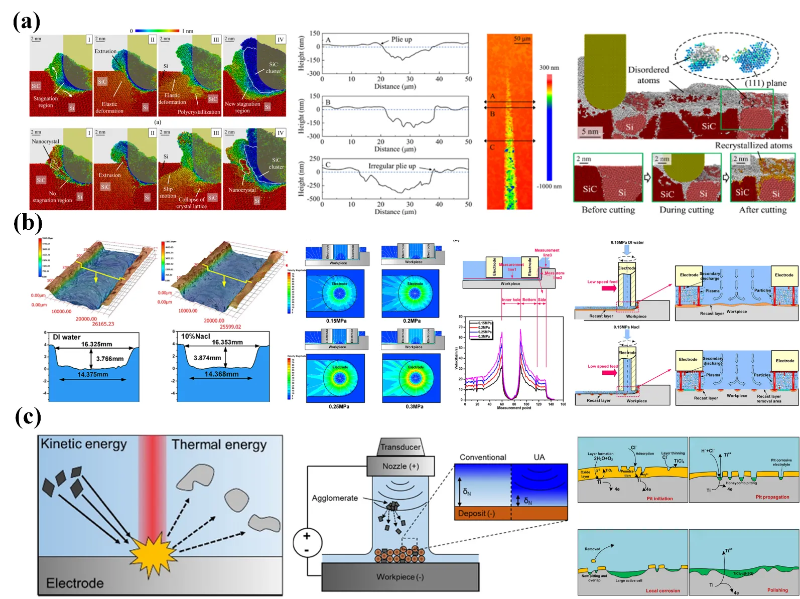
Recently, Zhu et al. [
106] adopted electrochemical grinding technology on stainless steel materials and the flowchart of the working method and the processing procedure are shown in a. To explore the electrochemical jet machining technology, Wirtz et al. [
107] improved the quality and accuracy of the workpiece through micromachining and surface modification. The relevant situation of mass transfer and the control effect during the electrodeposition process is shown in b. Compared with electrical discharge machining, Ahmet et al. [
108] found that electrochemical grinding could effectively improve surface roughness, which is closely related to the oxide film. The schematic diagram of the processing procedure and surface morphology processed under different pulse currents is shown in c. Ming et al. [
69] investigated the influence of magnetic field-assisted electrical discharge machining on the processing properties of magnetic and non-magnetic materials. The influence of the magnetic field on the movement of debris is shown in d. The discharge state is monitored in real time through the programmable system-on-chip, and the servo feed speed and planetary motion parameters are dynamically adjusted by the indirect self-tuning regulator. Meanwhile, the rotational magnetic field is utilized to accelerate the discharge of molten material. As for other difficult-to-machine alloys, Niu et al. [
109] processed Inconel 718 alloy through electrochemical assisted milling and grinding. The schematic diagram of the electrolyte flow and the flow velocity distribution of the cross-section during the machining process are shown in e. To explore new deep grinding technologies, improve processing performance, and solve problems such as grinding heat and wheel wear during the deep grinding process, Ge et al. [
110] carried out a series of electrochemical deep grinding experiments. During the electrochemical assisted grinding process, the anode material removal mechanism changes significantly. Mechanical grinding can not only scrape off the electrolytic products on the machined surface but also grind the insoluble components in the substrate, as shown in f.
. (<strong>a</strong>) Schematic diagram of the ultrasonic-assisted electrochemical grinding process, including the experimental setup and the sketch of the processing area [<a href="#B106" class="html-bibr">106</a>]. (<strong>b</strong>) The influence of hydrogen evolution and the mechanism of geometric and true flatness in electrodeposition [<a href="#B111" class="html-bibr">111</a>]. (<strong>c</strong>) Schematic diagram of the electrochemical grinding process of abrasives [<a href="#B108" class="html-bibr">108</a>]. (<strong>d</strong>) The influence of servo voltage on the formation of discharge pits and the magnetic field on the movement of debris [<a href="#B69" class="html-bibr">69</a>]. (<strong>e</strong>) The overall layout diagram of the magnetic field-assisted electrochemical machining machine tool [<a href="#B109" class="html-bibr">109</a>]. (<strong>f</strong>) Schematic diagram of the electrochemical deep grinding process and removal mechanism [<a href="#B110" class="html-bibr">110</a>].
The chemical energy field holds significant value in the micro-grinding of hard and brittle materials. Through technologies such as laser fields and electrochemical fields, the grinding accuracy, efficiency, and surface quality have been enhanced, providing an effective approach for the precise processing of hard and brittle materials. However, some challenges still need to be overcome. In the field of laser-assisted grinding, precisely controlling laser parameters is complex, and a large number of experiments are required to determine the optimal parameters. As for the electrochemical assisted grinding, issues such as electrolyte selection, electrode corrosion, and polarization could highly affect the processing stability. In the future, with the development of intelligent control systems, it is expected to achieve real-time optimization of chemical energy-field parameters. Meanwhile, the emergence of new materials will promote the development of more eco-friendly and stable electrolytes and corrosion-resistant electrodes, further enhancing processing stability and environmental friendliness.
3.2.2 Devices and Performance
During the laser-assisted grinding, various types of lasers are usually used to emit light beams, and most of them are equipped with scanners to inspect the surface condition of the workpiece. According to the positional relationship between the optical path and the spindle, lasers can be roughly classified into side-axis lasers (where the laser beam is in a position parallel to the grinding wheel), coaxial lasers (where the laser beam is coaxially arranged with the grinding wheel), and rear-mounted laser-assisted micro-grinding devices (where the laser emission device is set behind the grinding wheel). Hu et al. [
88] proposed a novel laser-assisted dry micro-grinding technology for fabricating micro-grooves of various workpieces such as cemented carbide, die steel, and quartz glass. The laser beam is focused on the chip rather than the workpiece.
Through the coupling of the thermal energy output by the laser and the shear heat, the chip is removed to obtain an intact surface (a). Yehia et al. [
112] employed an electrochemical assisted grinding machine, which is composed of an electrolyte tank, an electrolytic pump, a cathode wheel, a DC power supply,
etc., and is capable of mechanical operation (b). The NaCl solution was used as the electrolyte to study the influence of the electrolyte concentration and feed rate.
. (<strong>a</strong>) Experimental equipment for laser-assisted grinding process [<a href="#B88" class="html-bibr">88</a>]. (<strong>b</strong>) Experimental equipment for mixed abrasive electrochemical grinding, including electrolyte tank, cathode wheel, and DC power supply [<a href="#B112" class="html-bibr">112</a>]. (<strong>c</strong>) Experimental equipment includes the combination mode of a laser system and a 3-axis grinding machine [<a href="#B92" class="html-bibr">92</a>]. (<strong>d</strong>) Laser-assisted grinding experimental platform with CW-CO<sub>2</sub> laser, lathe, cutting tools and measuring instruments [<a href="#B98" class="html-bibr">98</a>]. (<strong>e</strong>) Physical diagram of the electrochemical processing system [<a href="#B113" class="html-bibr">113</a>]. (<strong>f</strong>) Principle of the electrochemical end face grinding device [<a href="#B114" class="html-bibr">114</a>]. (<strong>g</strong>) The main components of the experimental equipment including the machine tools, electrolyte supply, power supply, motion control and data acquisition units [<a href="#B110" class="html-bibr">110</a>].
In c, Ma et al. [
92] combined the fiber laser system with the three-axis grinding machine to achieve laser-assisted grinding. Song et al. [
98] adopted a CO
2 laser processing system, adjusted to a diameter of 3 mm through an optical system, and was used to irradiate the workpiece, as shown in d. Xu et al. [
115] used a 6-degree-of-freedom robotic arm equipped with a laser generator to ensure the accurate focusing position of the laser beam. In fact, it replaced the function of a machine tool with a robot. Xu et al. optimized the thermal environment of CNC grinding machines based on an improved neural network and designed an interface that could simplify the operation process, thereby streamlining the operation procedures [
116]. Zhang et al. [
113] adopted a five-axis CNC milling machine, which could achieve translation along the X, Y, and Z axes, rotation along the A and C axes, and rotation along the Z axis. The positive end of DC power supply is connected to a conductive rod, and the negative end is connected to an electrode. The power supply voltage, gap voltage and current are monitored through a signal acquisition system (e). Wang et al. [
114] adopted the self-developed electrochemical grinding system as the experimental device, which mainly includes a marble platform, three motion axes, an electric spindle, a machine tool control system, as well as an electrolyte circulation and filtration system. The workpiece is used as the anode, made of steel, and the grinding head serves as the cathode. In electrochemical assisted grinding, the processing quality and efficiency is improved by superimposing translational motions (including linear and circular translation), as shown in f. The processing equipment developed by Ge et al. [
110] mainly consists of the machine tool, power supply, motion control and data acquisition unit (g).
Furthermore, Liu et al. [
89] fabricated microgrooves on polished RB-SiC using a five-axis ultra-precision machine tool and found that compared with traditional processing, the cutting force and fluctuation of laser-assisted processing of silicon carbide (RB-SiC) were lower. Among them, the grain orientation and distribution fluctuate with the cutting force, and as the cutting temperature increases, as shown in a. Zhang et al. [
113] established a five-axis CNC milling machine. A box for circulating working fluid was placed on the clamping table, with fixtures installed inside and conductive rods connected. The flow field under different flushing pressures is demonstrated in b. It includes the flow velocity distribution cloud map, curve, and the movement trajectories of particles,
etc. Speidel et al. [
111] developed an electrolyte injection device in combination with a power supply and auxiliary equipment to achieve electrochemical injection grinding. The mass transfer control during the electrodeposition process and the dissolution process of titanium alloys in electrochemical jet machining were analyzed, as shown in c.
. (<strong>a</strong>) Mapping diagrams of the relative atomic displacements of workpiece undergoes four removal stages in nano-cutting process, the contour of the processing groove during laser-assisted processing, and the distribution of disordered atoms [<a href="#B89" class="html-bibr">89</a>]. (<strong>b</strong>) Groove contours, electrode shapes, and process indicators during processing with different media, and the flow fields under different flushing pressures [<a href="#B113" class="html-bibr">113</a>]. (<strong>c</strong>) Schematic diagrams of electrochemical jet, ultrasound-assisted processing, and co-deposition [<a href="#B111" class="html-bibr">111</a>].
In electrochemical field-assisted grinding, the traditional DC power supply is usually adopted to drive the electrochemical-assisted grinding device [
117,
118]. Direct current is transmitted through the electrolyte to the processing area, composed of the workpiece and grinding tools. In addition, there is a pulsed electrochemical-assisted grinding device with an output of intermittent pulsed current. There are some dynamic electrochemical-assisted grinding devices, which adopt a power supply combining direct current and pulse power to ensure that the material can undergo stable electrochemical dissolution [
119]. The positive and negative electrodes and electrolyte are generally selected based on the experimental purpose.
Conceptualization, W.W.; Methodology, Z.Z.; Validation, B.G.; Formal Analysis, C.M.; Investigation, Z.Z.; Writing—Original Draft Preparation, W.W. and Z.Z.; Writing—Review & Editing, W.W. and Q.W.; Visualization, Q.W.; Supervision, C.M.; Project Administration, C.M.; Funding Acquisition, C.M.
Not applicable.
Not applicable.
All of the data is available on request.
This study was supported by the National Natural Science Foundation of China (52275405), Natural Science Foundation of Hunan Province (2025ZYQ142, 2023RC1078, 2024JJ6039), and Natural Science and Technology Plan Project of Changsha City (kh2301003).
The authors declare that they have no conflict of interest.