1. Introduction
The rapid advancement of unmanned aerial vehicle (UAV) technology is reshaping multiple domains of modern society, with expanding applications ranging from precision agriculture monitoring [
1] and emergency disaster response [
2] to urban logistics distribution [
3] and border security patrols [
4]. However, the endurance capacity of UAVs remains a core bottleneck, constraining their large-scale deployment. Despite annual improvements in battery energy density, traditional battery technologies struggle to meet prolonged high-intensity operational demands due to inherent physicochemical limitations.
The current limitations in UAV endurance and wireless charging technology severely hinder the execution of mission-critical tasks across various fields. For instance, in agricultural operations, drones are often required to monitor vast farmlands continuously, yet their typical flight endurance is only approximately 30 min. Frequent landings for battery replacement disrupt data collection and reduce operational efficiency, while manual battery swaps or reliance on ground-based charging stations increase operational costs and complexity. Similarly, in emergency disaster response, UAVs must operate for extended periods to deliver supplies or assess damage. However, traditional charging methods requiring wired connections or battery replacements introduce additional labor and logistical costs. Urban logistics drones also face analogous issues. High-density delivery networks demand rapid charging cycles, yet existing charging solutions expose urban logistics drones to delays, necessitating frequent returns to fixed charging stations. These existing technological shortcomings highlight the urgent need for a robust, high-efficiency wireless charging solution that addresses these operational constraints while enhancing reliability and adaptability in dynamic environments.
Concurrently, wired charging or battery replacement in complex environments often faces dual safety and reliability challenges. Against this backdrop, contactless wireless power transfer (WPT) technology has emerged as a focal point for both academia and industry. By enabling energy transmission through electromagnetic field coupling, this technology promises to overcome the physical constraints of UAV energy supply and establish a new technical paradigm for sustained operations.
Current mainstream WPT technologies primarily rely on magnetic resonance coupling principles [
5], which achieve energy transfer via magnetic field interactions between resonators. Nevertheless, these systems exhibit significant practical limitations: transmission efficiency undergoes nonlinear attenuation with increasing distance, receiver position deviation induces impedance mismatch, and insufficient parameter self-adaptation in dynamic scenarios leads to efficiency collapse or system instability. Although optimization strategies such as multi-coil configurations [
6], dynamic frequency tracking [
7], and coordinated multi-transmitter control have been proposed, these approaches typically compromise system robustness or increase hardware complexity, failing to satisfy UAV engineering requirements for lightweight design and high reliability. Anthony et al. [
8] developed an autonomous UAV charging platform utilizing machine vision to capture landing trajectories, enabling precise alignment with wireless charging stations. While achieving centimeter-level positioning accuracy, the system’s structural complexity results in prolonged landing durations, rendering it impractical for widespread real-world implementation.
For UAVs, their unique structural configurations necessitate specific modifications to traditional wireless charging coils to ensure compatibility with the aerial platform. Reference [
9] proposed an orthogonally coupled wireless charging system for UAVs, where the receiver coil was mounted on the landing gear and maintained a 90-degree vertical alignment with the transmitter coil, achieving 87% charging efficiency at 100 W power output. In reference [
10], a nonlinear parity-time (PT) symmetric principle was employed to construct a UAV wireless charging device, with the receiver coil positioned on the ventral side of the UAV, enabling power delivery at 10 W. Reference [
11] innovatively redesigned the UAV’s anti-collision frame by replacing it with a receiver coil, while studies [
12,
13] implemented planar air-core spiral coils beneath the landing gear for power transmission. Through a comprehensive analysis of these structural adaptations and their operational impacts, this study adopts the configuration with minimal interference to UAV functionality—installing the receiver coil beneath the landing gear for wireless charging implementation.
The compensation network constitutes a vital component in wireless charging systems, as the design of distinct compensation topologies enables diverse power transmission characteristics. In the abbreviation system outlined in , L represents inductor, C denotes capacitor, S signifies series compensation, and P indicates parallel compensation. Specifically, the LCL-S configuration adopts an inductor-capacitor-inductor (LCL) compensation network on the transmitter side and series capacitor compensation on the receiver side, while the S-S topology utilizes series capacitor compensation on both transmitter and receiver sides. The LCL-P structure combines an LCL-compensated transmitter with a parallel capacitor-compensated receiver, whereas the LCC-P configuration employs an inductor-capacitor-capacitor (LCC) compensation network on the transmitter side paired with a parallel capacitor-compensated receiver. This systematic nomenclature facilitates the precise characterization of compensation network architectures in wireless power transfer research.
. Unmanned aerial vehicle receiving coil.
In recent years, the Parity-Time (PT) symmetry principle [
13], originating from quantum mechanics, has provided revolutionary insights for WPT system design. PT-symmetric systems realize real eigenvalue spectra within non-Hermitian Hamiltonian frameworks through meticulously designed gain-loss distributions, thereby eliminating traditional reliance on strict Hermiticity. This characteristic endows PT-symmetric systems with unique energy regulation capabilities in optical waveguides and acoustic metamaterials, manifesting as high-sensitivity responses near exceptional points, unidirectional reflectionless transmission, and enhanced robustness under perturbations. Theoretically, integrating PT-symmetry into WPT systems could enable efficient and stable energy transmission within specific parameter ranges through dynamic gain-loss balancing. However, existing research predominantly focuses on theoretical verification under low-power static conditions, while applications in high-power dynamic systems (e.g., UAV wireless charging) confront multiple challenges.
First, PT symmetry implementation requires precise parameter matching, yet inevitable positional variations during UAV charging induce dynamic coupling coefficient fluctuations that disrupt gain-loss equilibrium. Second, under high-frequency, high-power operation, nonlinear effects in circuit components (e.g., magnetic core saturation and parasitic capacitance coupling) may drive systems away from PT-symmetric phases, causing efficiency degradation or oscillatory instability. To address these challenges, this paper proposes a high-efficiency UAV wireless charging system based on PT-symmetry principles. By constructing a non-Hermitian coupled resonator model, the system achieves efficient energy transmission through a dynamic balance between gain and loss units. Integrated with real-time parameter feedback mechanisms, the system adaptively compensates for coupling variations induced by UAV positional deviations, maintaining PT-symmetric phase stability. Compared with existing technologies, this design eliminates reliance on complex relay structures or high-precision positioning while significantly enhancing environmental adaptability without compromising transmission efficiency. Theoretical analyses and experimental results demonstrate that the proposed solution achieves stable high-efficiency energy transmission across typical UAV charging distances, exhibiting strong tolerance to horizontal receiver displacements. This work not only provides theoretical foundations for PT-symmetry applications in WPT but also pioneers new technical pathways for UAV endurance breakthroughs.
The paper is organized as follows: Section 2 elaborates on the implementation mechanism of PT symmetry in electromagnetically coupled systems and its role in regulating transmission efficiency; Section 3 details the system architecture design, parameter optimization methods, and dynamic control strategies; Section 4 experimentally validates the performance advantages of the system; Section 5 conducts a cost analysis, discusses industrial-scale implementation solutions, and examines the system’s limitations; Section 6 summarizes the entire paper and outlines future research directions.
2. System Overview and Modeling
2.1. System Circuit Structure
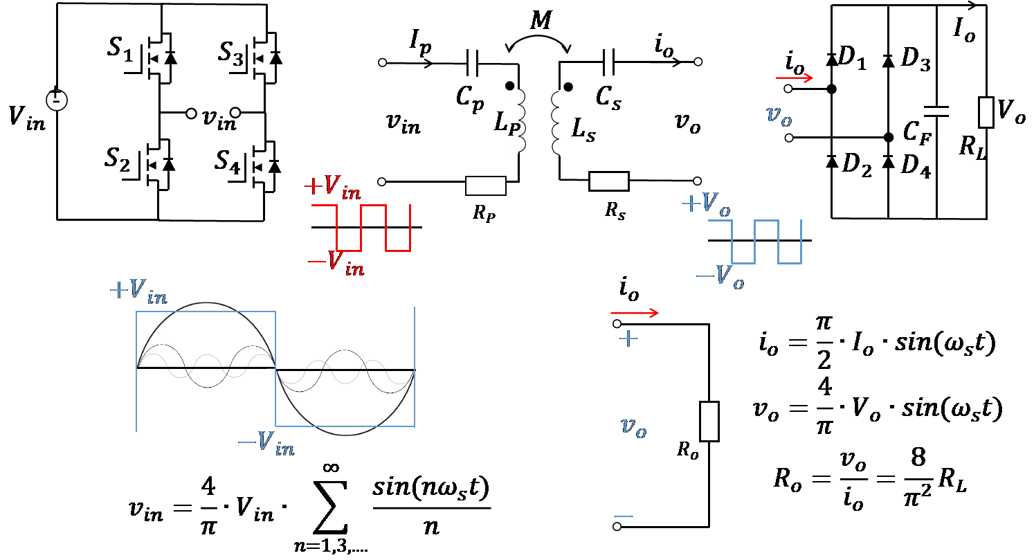
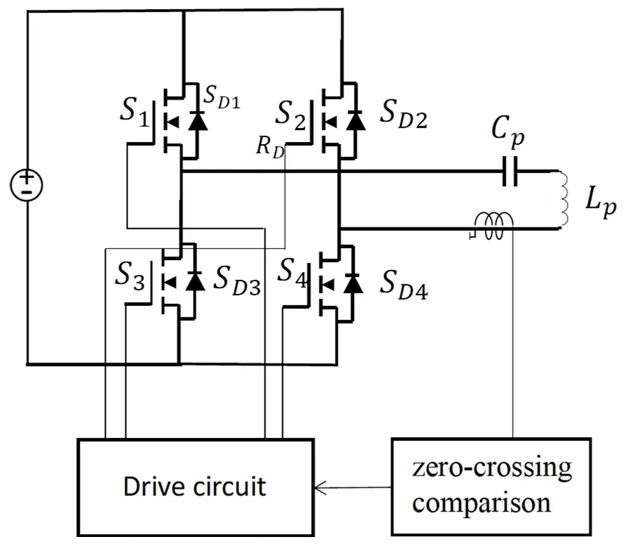
The wireless charging system for unmanned aerial vehicles (UAVs) primarily consists of two components. The first part is the transmitter located on the ground side, which comprises a DC power source
Vin, a full-bridge inverter circuit
S1−
S4, a transmitter-side compensation capacitor
Cp, the equivalent self-inductance of the transmitter coil
Lp, and the internal resistance of the transmitter coil
Rp. The second part is the receiver module on the UAV side, which includes the self-inductance of the receiver coil
Ls, the receiver-side compensation capacitor
Cs, the equivalent internal resistance of the receiver coil
Rs, a rectifier bridge
D1−
D4, an output filter capacitor
CF, and a load
RL.
As shown in
, the analytical expression of the high-frequency AC voltage
vin can be obtained through Fourier series expansion:
. System circuit structure.
The expression for the equivalent load resistance $$R_{o}$$ is given by:
During system operation, the DC input $$V_{i n}$$ is first converted into high-frequency AC $$v_{i n}$$ via the inverter bridge. The resulting signal then passes through the transmitter-side compensation capacitor Cp and the transmitter coil Lp, generating a high-frequency alternating magnetic field in the transmitter coil. The receiver coil is magnetically coupled to the transmitter coil via mutual inductance M, harvesting energy by capturing the alternating magnetic field. Subsequently, the received energy is processed through the receiver-side compensation capacitor Cs, the rectifier bridge, and the filter capacitor CF before being delivered to the load.
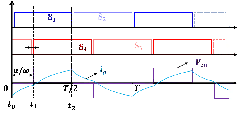
As shown in
, the high-frequency alternating current
vin is generated using a frequency-variable phase-shifting method. The switches
S1,
S2 and
S3,
S4 are driven by two sets of complementary PWM signals respectively. When
S1 and
S4 are turned on while
S2 and
S3 are turned off, a positive half-cycle waveform with amplitude of
Vin is generated. Conversely, when
S1 and
S4 are turned off while
S2 and
S3 are turned on, a negative half-cycle waveform with amplitude of −
Vin is produced. By controlling the phase delay between
S1,
S2 and
S3,
S4 switching pairs, the duty cycle of the high-frequency AC
vin can be effectively regulated.
. Frequency-Variable Phase-Shifted Full-Bridge Inverter Waveform.
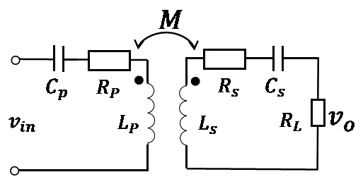
Thus, the entire wireless power transfer circuit can be equivalent to the equivalent circuit shown in
. This equivalent circuit consists of a high-frequency AC source
vin, a transmitting-end compensation capacitor
Cp, a transmitting-end coil self-inductance
Lp, a transmitting-end internal resistance
Rp, a receiving-end coil self-inductance
Ls, a receiving-end compensation capacitor
Cs, and a receiving-end internal resistance
Rs.
. Equivalent circuit diagram of WPT system.
In recent years, parity-time (PT) symmetry, as a novel non-Hermitian system regulation theory, has demonstrated unique application potential in the field of wireless power transfer (WPT). Originally proposed by Bender and Boettcher in 1998 within quantum mechanics, PT symmetry is fundamentally characterized by a system maintaining Hamiltonian invariance under the combined operations of parity (spatial inversion) and time reversal. Unlike traditional Hermitian systems, PT-symmetric systems permit precise balancing of gain and loss, thereby enabling real energy spectra and stable eigenmodes within specific parameter regimes. This property provides a new paradigm for energy regulation in classical wave systems, such as electromagnetic fields and acoustic waves.
In the context of WPT, PT symmetry has been introduced to address the efficiency sensitivity inherent in traditional magnetically coupled resonant systems. Conventional approaches rely on strong coupling and frequency matching between transmitting and receiving resonators, yet their transmission efficiency is highly susceptible to distance variations, load fluctuations, and environmental interference. Systems based on PT-symmetry principles establish a dynamic synergy between gain and loss terminals, allowing stable energy transfer under asymmetric parameter conditions. Specifically, when a system operates in the PT symmetry-broken phase, energy exhibits unidirectionally enhanced flow between terminals, whereas in the PT-symmetric phase, oscillatory energy exchange dominates. Such dynamic tunability enables PT-symmetric systems to adapt to complex operational demands, such as coupling coefficient fluctuations caused by drone attitude or distance variations during flight. Current research highlights two core advantages of PT-symmetric WPT systems: first, through active gain-loss regulation, these systems achieve highly efficient directional near-field energy transfer at critical coupling points. Second, their robustness against environmental disturbances significantly surpasses that of conventional resonant coupling schemes.
The coupled-mode model employs the modal amplitudes
ap and
as of the transmitter and receiver resonant networks to characterize variations in their stored energy, where the stored energy is quantified by |
ap|
2 and |
as|
2, respectively. By selecting
ap and
as as state variables, the coupled-mode equations governing the system illustrated in
can be derived as follows:
In the equation,
g =
g10 = Γ
10 represents the total gain at the transmitter side, where
g10 and Γ
10 denote the gain rate provided by the negative resistance and the intrinsic loss rate of the transmitter coil, respectively, with
g10 = $$v_{i n}$$/(2
Lp), Γ
10 =
Rp/(2
Lp). The total loss rate at the receiver side is given by Γ = Γ
L + Γ
20, where Γ
L is the load loss rate, and Γ
20 is the intrinsic loss rate of the receiver coil,Γ
L =
RL/(2
LS), Γ
20 =
RS/(2
LS), the coupling coefficient between the coils is $$k = M / \sqrt{L_{p} L_{s}}$$.
Performing parity inversion (
ap↔
as) and time reversal (
t↔
−t,
j↔−
j) on the system described by
Equation (3) yields the following coupled-mode equations:
From
Equation (3) and
Equation (4), it follows that to preserve the system’s invariance under parity-time reversal, the conditions ω
p = ω
s = ω
0 and
g = Γ must hold. Expressed in terms of circuit parameters, these requirements translate to$$1 / \sqrt{L_{p} C_{p}} = 1 / \sqrt{L_{s} C_{s}}$$. From a physical implementation perspective, this necessitates (1) Strict matching of the intrinsic resonant frequencies between the transmitter and receiver coils; (2)The design of a self-adjusting nonlinear saturable negative resistor to dynamically equilibrate the total gain rate at the transmitter with the total loss rate at the receiver. When the system parameters are matched and the condition ω
p = ω
s = ω
0 is satisfied, the characteristic equation of the system can be derived from
Equation (3) as:
By separating the real and imaginary parts of
Equation (5) and setting them equal to zero respectively, we obtain:
By solving
Equation (6), the expression for the steady-state solution can be obtained as: ω = ω
0, $$\omega_{H} = \omega_{0} + \sqrt{\kappa^{2} - \Gamma^{2}} , \omega_{L} = \omega_{0} - \sqrt{\kappa^{2} - \Gamma^{2}}$$. The critical coupling coefficient is defined as
κ =
κc. For
Equation (6), when
κ ≥
κc, three solutions exist, denoted as ω
0, ω
H, ω
L. According to Lyapunov stability theory, the solution ω
0 is unstable [
9]. Furthermore, since the system satisfies
g − Γ,under this condition, only two solutions (ω
H, ω
L) remain valid when
κ ≥
κc.When
κ <
κc, only a single real solution ω
0 exists. Consequently, the system operates at ω = ω
0. From
Equation (6), the gain provided by the negative resistance is derived as
g =
κ2/Γ. Since this fails to satisfy the condition
g ≠ Γ, the system is said to operate in the PT-symmetry-broken phase. Based on the preceding analysis, the system’s operational regime can be classified into PT-symmetric and PT-symmetry-broken phases according to the relationship between the system’s coupling coefficient
κ and its critical value
κc:
- ①
-
Symmetric and antisymmetric solutions (κ ≥ κc):
In the PT-symmetric regime where the system operates at ω
H, ω
L, substituting into
Equation (7) reveals an equal amplitude relationship between energy modes: |
a1|/|
a2| = 1. According to coupled-mode theory, the system’s output power
Po and transmission efficiency
η can be expressed as:
Equation (8) and
Equation (9) demonstrate that within the PT-symmetric regime, both the output power and transmission efficiency of the system remain independent of the coupling coefficient. Moreover, since the load dissipation typically dominates over the coil’s internal resistance losses, the system can achieve high transmission efficiency.
- ②
-
Asymmetric solution (κ < κc):
In the PT-symmetry-broken phase where the system operates at ω = ω
0,
Equation (7) yields an imbalanced amplitude relationship between energy modes: |
a1|/|
a2| = Γ/
k > 1. In this regime, the system exhibits reduced efficiency, with its output power and transmission efficiency given by:
Therefore, the magnetic field coupling region can be divided into strong and weak coupling zones based on the PT-symmetric condition. In the strong coupling zone, the system satisfies the PT-symmetric condition. In the weak coupling zone, the system fails to meet the PT-symmetric condition, and the operating frequency corresponds to the system's inherent resonant frequency. The physical interpretation is that the strong coupling zone represents the PT-symmetric region, while the weak coupling zone corresponds to the non-PT-symmetric region.
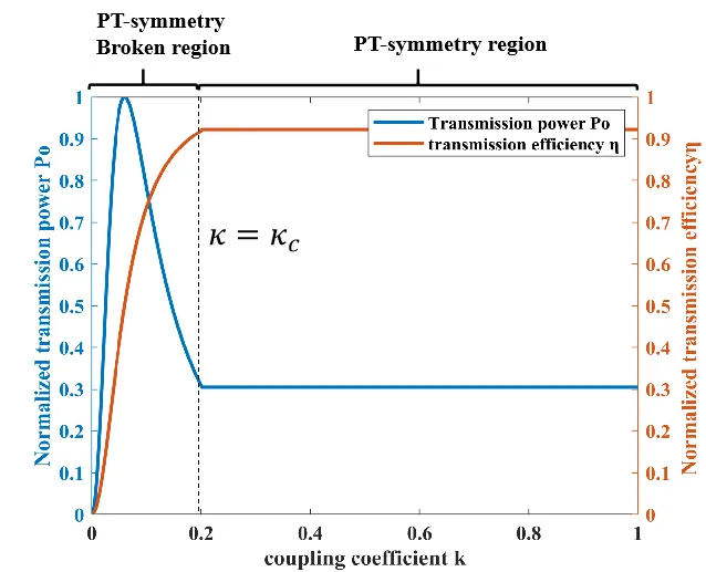
demonstrates the output characteristics of the parity-time symmetric wireless power transfer system. For the coupling coils in wireless power transfer systems, the coupling coefficient between coils gradually decreases as the inter-coil distance increases. When the inter-coil distance is relatively small with a coupling coefficient k > kc, the system operates in the PT-symmetric region (also referred to as the strong coupling regime). In this operational state, both the output power and system efficiency remain invariant with variations in the coupling coefficient, indicating that the system exhibits misalignment resistance where distance variations between coils do not affect its operational performance.
As the inter-coil distance increases and the coupling coefficient diminishes to
κ <
κc, the system transitions into the PT-broken region (termed the weak coupling regime). Within this operational domain, the system efficiency demonstrates a progressive decline with a decreasing coupling coefficient, accompanied by significant power deviation. Consequently, the system loses its robustness against variations in inter-coil distance within the PT-broken region.
. The relationship between output power, efficiency, and coupling coefficient.
3. Construction of the Coupling Structure and Control System
3.1. Design of Coupling Structure
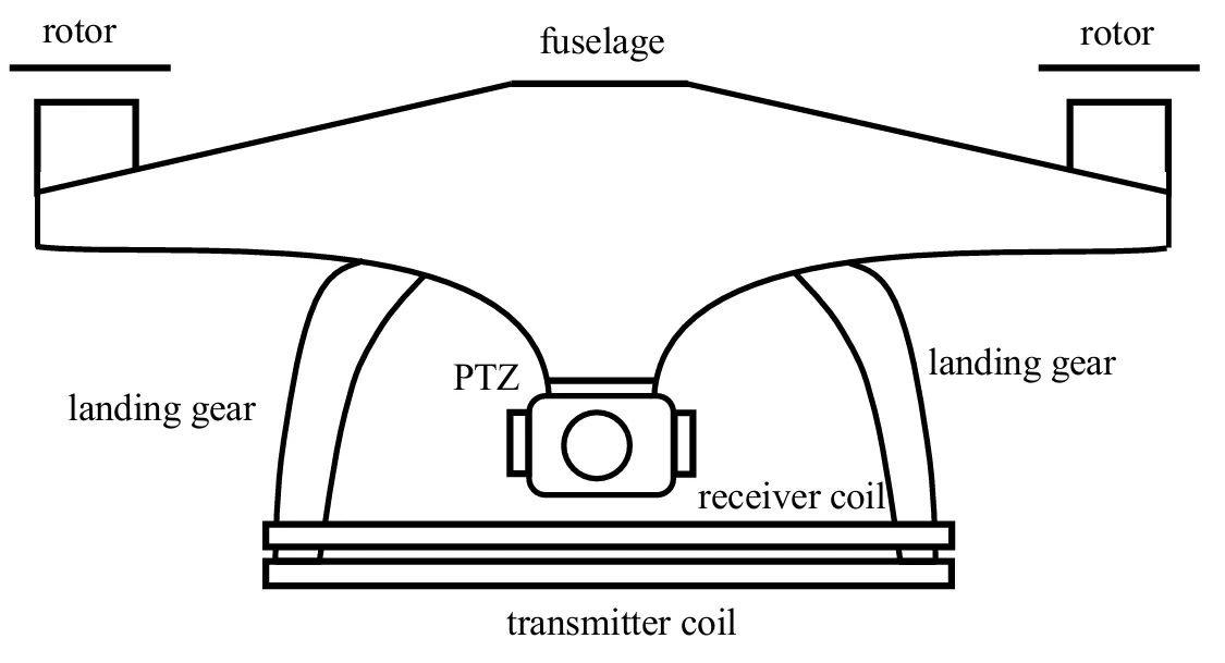
An unmanned aerial vehicle (UAV) is a complex aircraft composed of multiple critical systems.As illustrated in
, its typical structure includes a lightweight airframe (usually made of carbon fiber or aluminum alloy), a propulsion system (consisting of brushless motors, propellers, and electronic speed controllers), a power system (primarily using lithium polymer batteries), a flight control system (incorporating sensors such as main control chips, IMU inertial measurement units, barometers, magnetometers, and GPS modules), a communication system (encompassing remote control links, data transmission, and video transmission modules), mission payloads (such as camera gimbals or specialized detection equipment), and auxiliary systems (including obstacle avoidance sensors and navigation lighting). To minimize the impact of wireless charging coils on the UAV, the receiving coil of the proposed wireless charging system in this study is installed beneath the drone’s landing gear.
Figure 5. Schematic diagram of coupling coil installation position.
The transceiver coil model is further simplified. As illustrated in
,
Din1,
Dout1,
rin1,
rout1,
w1,
p1,
N1 are the outer diameter, inner diameter, outer radius, inner radius, wire diameter, turn spacing, and number of turns of the transmitting coil.
Din2,
Dout2,
rin2,
rout2,
w2,
p2,
N2 are the outer diameter, inner diameter, outer radius, inner radius, wire diameter, turn spacing, and number of turns of the receiving coil, where μ₀ is the vacuum permeability,
Davg is the coil’s mean diameter, and the self-inductance formulas are as follows:
The mutual inductance M between the two coils is calculated by:
. Schematic diagram of a planar air-core coil.
As illustrated in
, this study establishes a three-dimensional electromagnetic simulation model of a drone wireless charging system using COMSOL Multiphysics software. The transmitting and receiving coils adopt planar rectangular air-core structures, each with a side length of 40 cm. These coils are arranged symmetrically in a parallel configuration, with a central vertical spacing of 3 cm to simulate typical charging scenarios during drone hovering. The geometric parameters of the coils strictly adhere to design specifications: the conductor diameter is 1.98 mm, featuring a 10-turn tightly wound structure with inter-turn spacing controlled within 0.5 mm, ensuring optimal balance between coil compactness and electromagnetic performance. The simulation model is enclosed within a 1 m³ cubic air domain, where outer boundaries are assigned magnetic insulation conditions to eliminate external environmental interference. The computational domain is discretized using free tetrahedral meshing, with boundary layer mesh refinement implemented on coil surfaces to enhance numerical accuracy.
. Magnetic Field Simulation.
In the physical field configuration, the magnetic fields module is employed for frequency-domain quasi-static analysis, operating at a resonant frequency of 50 kHz. The coil conductor material is defined as copper (conductivity 5.998 × 10
7 S/m), with magnetic core losses intentionally neglected to focus on air-core coil characteristics. Simulation results demonstrate a characteristic bimodal distribution of induced magnetic field intensity at the receiver, forming an effective energy transmission window in the central region. Thus, it is essential to maximize the alignment accuracy between the transmitting and receiving coils to achieve optimal coupling conditions. These findings validate the rationality of the model parameter design and the reliability of the simulation methodology.
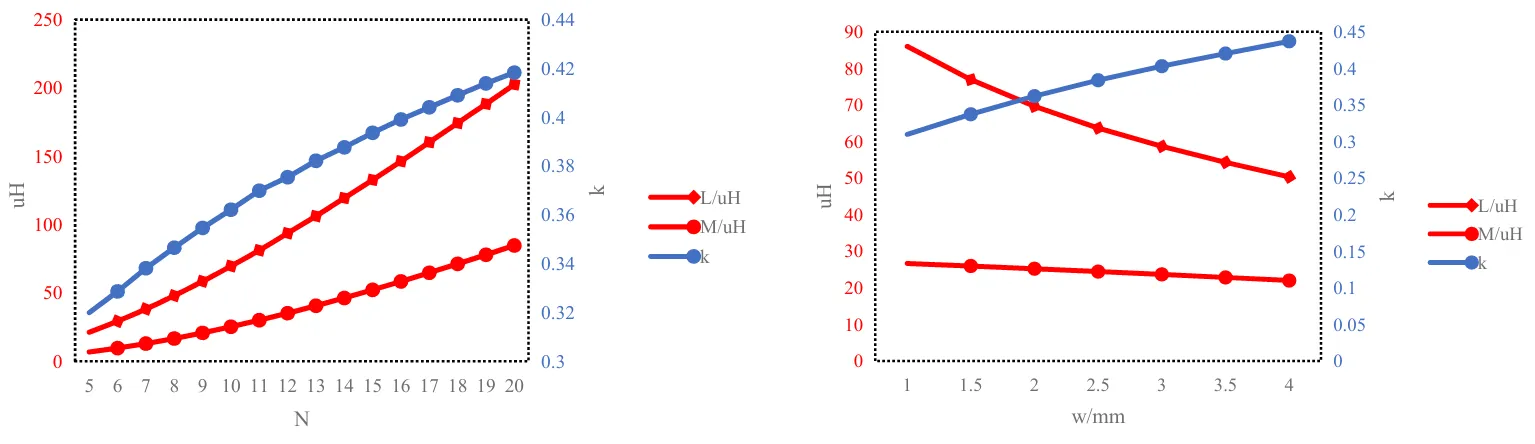
As illustrated in
, when employing a wire diameter of 2 mm and turn spacing of 0.2 mm, the coil’s self-inductance, mutual inductance, and coupling coefficient all exhibit an increasing trend with the augmentation of winding turns. Notably, the growth rate of the coupling coefficient gradually decelerates at approximately 13–14 turns. Consequently, appropriately increasing the number of winding turns within a reasonable range can effectively enhance the coupling coefficient, thereby enabling the system to enter the PT-symmetric strong coupling regime. However, excessive winding turns should be avoided to prevent undesirable weight increases and excessive DC internal resistance. Simultaneously, under constant other parameters, increasing the wire diameter of the coil can improve the coupling coefficient, but this modification leads to reductions in both self-inductance and mutual inductance. Therefore, the comprehensive parameter design of the system requires balanced consideration of all variables to achieve optimal performance.
. Impact of Turns and Wire Diameter on System Parameters.
To validate the dynamic performance and control strategy effectiveness of the drone wireless charging system, this paper develops a full-system simulation model on the MATLAB/Simulink platform, which integrates power converters, magnetic coupling mechanisms, and closed-loop control circuits. The complete simulation parameters of the system are summarized in
.
Lp denotes the self-inductance of the transmitting coil,
Ls represents the self-inductance of the receiving coil, Cp stands for the compensation capacitance at the transmitter side,
Cs indicates the compensation capacitance at the receiver side, $$R_{p}$$ signifies the internal resistance of the transmitter, $$R_{s}$$ refers to the internal resistance of the receiver, $$R_{L}$$ is the load resistance, M designates the mutual inductance, $$V_{i n}$$ corresponds to the DC input voltage, and f indicates the operating frequency.
.
Simulation parameters.
| Parameter |
Value |
Parameter |
Value |
| Lp/uH |
55.93 |
$$R_{p}$$ |
0.1–0.25 |
| Ls/uH |
44.14 |
$$R_{s}$$/Ω |
0.1–0.2 |
| Cp/nf |
55.93 |
$$R_{L}$$/Ω |
10 |
| Cs/nf |
44.14 |
$$M$$/uH |
30.76 |
| $$V_{i n}$$/V |
20 |
f/kHz |
100 |
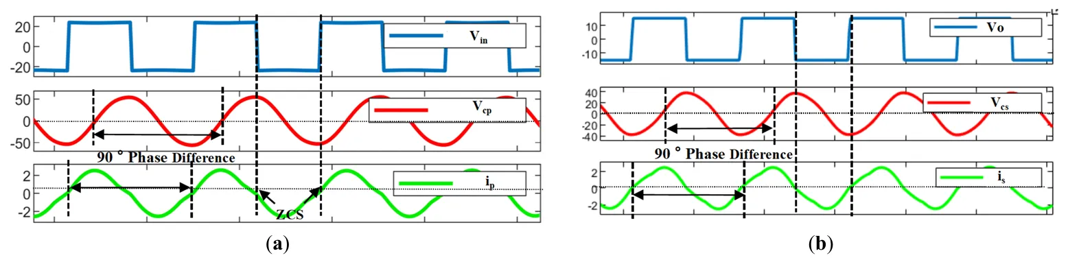
illustrates the transmitter-side and receiver-side waveforms within the PT-symmetric region. As depicted in
a, the high-frequency alternating current $$v_{i n}$$ generated by the inverter bridge from the DC source $$V_{i n}$$ exhibits optimal commutation characteristics: the transmitter current $$i_{p}$$ crosses zero precisely during switching transitions, maximizing system efficiency. Concurrently, a 90-degree phase difference between the compensation capacitor voltage and current ensures resonant operation.
b demonstrates the energy transfer process at the receiver. The induced energy from the receiver coil undergoes sequential processing through the compensation capacitor, rectifier bridge, and filter capacitor before delivery to the load. Notably, the post-compensation voltage $$v_{o}$$ remains phase-synchronized with the receiver current, achieving critical soft-switching conditions that minimize switching losses.
. PT-Symmetric Region. (<b>a</b>) Transmitter-side Waveform; (<b>b</b>) Receiver-side Waveform.
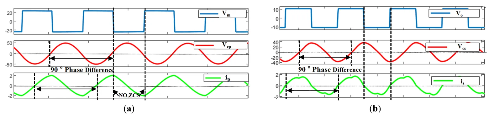
presents the transmitter-side and receiver-side waveforms in the PT-symmetry-broken phase. When the system operates in this regime, its output power efficiency strongly depends on the coupling coefficient. As shown in
a, the high-frequency AC voltage $$v_{i n}$$ at the transmitter loses phase synchronization with the current $$i_{p}$$, where the current deviates from the zero-crossing point during switching transitions, resulting in reduced transmission efficiency. Notably, the compensation capacitor maintains a 90° voltage-current phase relationship, preserving resonant behavior despite symmetry breaking.
b reveals that the receiver-side waveforms remain consistent with those in the PT-symmetric region (
b), indicating that energy transfer degradation primarily originates from transmitter-side phase misalignment. To ensure stable operation within the PT-symmetric region, an adaptive transmitter-side control scheme is essential for maintaining constant power delivery and high efficiency across variable coupling conditions.
. PT-Symmetry-Broken Phase. (<b>a</b>) Transmitter-side Waveform; (<b>b</b>) Receiver-side Waveform.
To achieve in-phase control, a coordinated strategy must be implemented at the transmitter side. As illustrated in
, current sampling at the transmitter, zero-crossing detection during switching transitions, and adaptive switching frequency adjustment are required to ensure the system satisfies the PT-symmetry condition. This comprehensive approach enables precise phase synchronization while maintaining optimal resonant characteristics.
Figure 11. Schematic diagram of frequency tracking control.
4. Prototype Construction and Experimental Verification
To validate the feasibility of the parity-time symmetric wireless power transfer system for unmanned aerial vehicles (UAVs), an experimental prototype was designed and constructed in this study. The core components of the system are the transmitting and receiving coupled coils, whose geometric parameters and winding configurations were determined based on theoretical optimization results.
The dimensional parameters of the coil are presented in
. Both transmitting and receiving coils adopt a rectangular hollow structure, with each coil featuring an outer contour dimension of 280 mm × 280 mm and an inner contour dimension of 270 mm × 270 mm, aiming to maximize the effective coupling area. Each coil comprises 10 tightly wound turns (with inter-turn spacing approaching zero) to enhance equivalent mutual inductance density. To further suppress high-frequency skin effects and proximity-induced losses, the coils were fabricated using multi-strand Litz wire, with a single-strand diameter of 1.98 mm. Optimized stranding techniques were employed to minimize high-frequency impedance during the manufacturing process.
.
Coil physical parameters.
|
Parameter |
Values |
|
Parameter |
Values |
| TX Coil |
shape |
rectangle |
RX Coil |
shape |
rectangle |
| number of turns |
10 |
number of turns |
10 |
| Internal dimensions |
270 × 270 |
Internal dimensions |
270 × 270 |
| External dimensions/mm |
280 × 280 |
External dimensions |
280 × 280 |
| Wire Width/mm |
1.98 |
Wire Width |
1.98 |
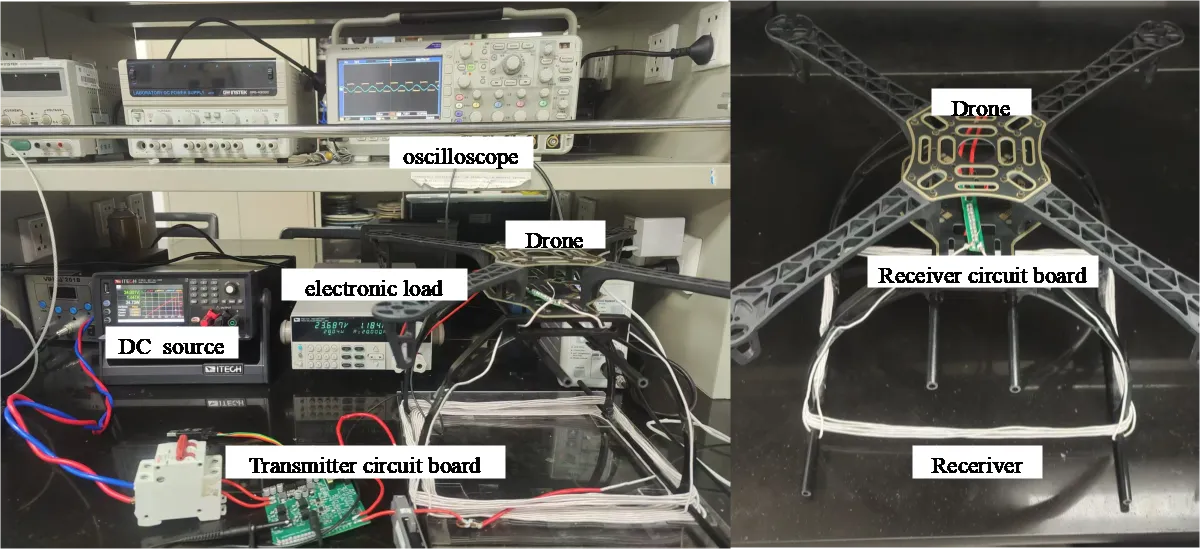
presents the prototype of the wireless power transfer (WPT) experimental platform developed in this study. The system architecture comprises the following key functional modules: (1) Signal acquisition and analysis module, incorporating a high-performance digital oscilloscope for real-time waveform monitoring; (2) Power supply module, featuring an adjustable DC source with programmable voltage/current regulation; (3) Load emulation module, employing an electronic load device for dynamic impedance simulation; (4) Energy transmission unit, integrating the transmitter-side control circuitry and specially-optimized transmitting coil; (5) Energy reception unit, consisting of the receiver-side rectification circuit and receiving coil assembly.
. Experimental prototype.
Notably, the transmitting coil adopts a space-efficient design by being concentrically wound beneath the UAV landing gear structure. This innovative configuration achieves dual optimization: maintaining excellent electromagnetic coupling performance while satisfying the stringent spatial constraints of aerial vehicle integration. Through systematic coordination of these modular components, the experimental platform establishes a comprehensive closed-loop testing environment for WPT system evaluation, enabling rigorous characterization of power transfer efficiency, dynamic response, and operational stability under various loading conditions.
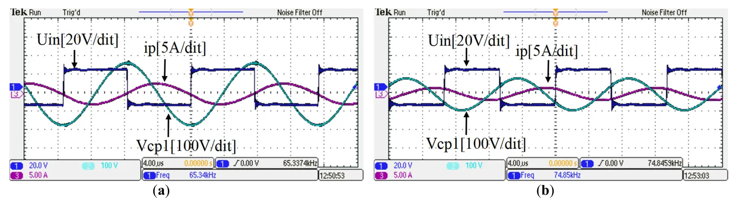
a,b comparatively demonstrate the dynamic characteristics of the transmitter under PT-symmetric and PT-broken phases in the wireless power transfer system (experimental conditions: input voltage 20 V, input current 3.25 A). Under the PT-symmetric phase
, the system exhibits typical resonant features: the high-frequency AC voltage
vin at the transmitter maintains strict phase synchronization with the coil current
ip, while the voltage commutation instant precisely coincides with the current zero-crossing point. Simultaneously, the compensation capacitor voltage
Vcp reaches its peak magnitude, exhibiting a consistent 90° phase lag relative to
ip, which confirms the system’s optimal energy transfer state.
In contrast, under the PT-broken phase
b, the system manifests distinct non-ideal behaviors: a significant residual current persists during
vin commutation, leading to increased switching losses. Furthermore, both the transmission efficiency
η and output power
Po exhibit nonlinear degradation with variations in the coupling coefficient
κ. This observed phase transition aligns with the theoretical prediction that PT-symmetry breaking induces system efficiency deterioration, thereby experimentally validating the critical influence of the coupling coefficient on operational modal characteristics.
. Transmitter experimental waveform. (<b>a</b>) PT symmetric region; (<b>b</b>) PT symmetric broken region.
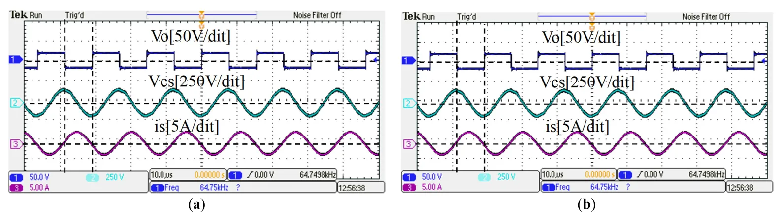
As shown in
, whether in the PT-symmetric state or the PT-symmetry-broken state, the voltage waveform of the compensation capacitor at the receiving end and the current waveform at the receiving end maintain a 90-degree phase difference. During voltage commutation, the current crosses zero.
Figure 14. Receiver experimental waveform. (<b>a</b>) PT-symmetric region; (<b>b</b>) PT-symmetric broken region.
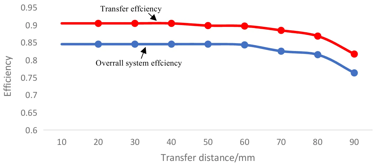
The efficiency curve is shown in
. Since the transmitting and receiving coils are identical in size, the transmission distance is characterized by the center-to-center distance between the coils. In the strong coupling region, the system’s transmission efficiency remains relatively stable at approximately 90%, while the overall system efficiency maintains around 85%. The operating frequency of the system matches the calculated results well.
Figure 15. Transmission efficiency and transmission distance curve.
summarizes the operating frequency, efficiency, and power of similar studies. Although the approach by Anthony et al. [8] achieves 87% efficiency, it requires a mechanical positioning platform, whereas our system employs electrical tuning for rapid compensation; the 6.78 MHz system in Reference [14] exhibits only 50% efficiency at 12 W output power, indicating that high-frequency solutions suffer from severe skin-effect losses in UAV applications. The experimental validation in this study demonstrates that at a typical working distance of 3 cm, the system achieves a transmission efficiency of 90.2% with 65 W output power. The system demonstrates exceptional stability in the strong coupling region. Furthermore, without relying on complex relay coil structures or high-precision positioning devices, the system adapts to dynamic variations in UAV landing postures through dynamic phase synchronization control algorithms, effectively reducing hardware complexity and deployment costs.
.
Comparison with existing work.
| Reference |
Frequency(Mhz) |
Transfer Efficiency |
Power(W) |
Operation Condition |
| [15] |
0.13 |
28–63% |
5–52 |
Fixed |
| [16] |
0.0379 |
90% |
130 |
Fixed |
| [17] |
0.15 |
89% |
70 |
Fixed |
| [14] |
6.78 |
50% |
12 |
Fixed |
| [18] |
13.56 |
-- |
10 |
variable |
| This paper |
0.12 |
90.2% |
65 |
variable |
5. Discussion
5.1. Cost and Industrial Scalability Analysis
The proposed PT-symmetric wireless charging system demonstrates significant technical advantages, yet its industrial scalability and economic viability require further analysis. From a cost perspective, the system primarily comprises planar air-core coils, high-frequency inverters, adaptive control circuits, and lightweight receiver modules. The planar coils, fabricated using multi-strand Litz wire (1.98 mm strand diameter), incur material costs of approximately $2–$3 per coil (based on 2024 copper prices), while the full-bridge inverter and DSP-controlled feedback system add $15–$20 per transmitter unit. Compared to conventional WPT systems, this design eliminates the need for precision positioning mechanisms, thereby reducing hardware costs. The economic analysis confirms the system’s competitiveness, with a projected unit cost of $25–$30 for mass-produced transmitters, significantly lower than laser-based charging alternatives ($800+). Future work will reduce costs, paving the way for large-scale UAV charging networks.
The technology can be further applied in logistics centers. By simply equipping each drone with a receiving coil and receiver circuit, automatic charging in warehouse hubs can be achieved, enabling continuous drone delivery operations and further reducing warehousing costs. Moreover, the system can be deployed in agricultural fields and integrated with solar-powered charging stations to support 24/7 crop monitoring by drones. Additionally, the wireless charging transmitters can be installed on power transmission towers, allowing inspection drones to recharge wirelessly when running low on battery. This would significantly extend the range of power line inspections.
5.2. Limitations and Technical Challenges
While the proposed PT-symmetric wireless charging system demonstrates significant efficiency and misalignment tolerance advantages, several technical limitations merit discussion. First, The real-time gain-loss balancing mechanism relies on high-speed DSP processors and precision current sensors, which increases the system’s hardware complexity and presents implementation challenges for low-cost microcontrollers. Secondly, the system’s high-frequency operation (50 kHz) generates non-negligible electromagnetic radiation. While the planar air-core coil design minimizes core magnetic losses, the absence of ferrite shielding may cause interference when operating near metallic structures or other WPT devices, leading to reduced system efficiency.
These limitations highlight the next research directions, including simpler control schemes, EMI shielding architectures, and the manufacturing of lightweight coils. Addressing these limitations will further increase the feasibility of commercial and industrial applications.
6. Conclusions
To address the critical challenges of limited endurance in unmanned aerial vehicles (UAVs) and the inherent limitations of conventional wireless charging systems—particularly efficiency degradation with transmission distance and insufficient dynamic stability—this study presents a high-efficiency UAV wireless charging system based on the parity-time (PT) symmetric principle. By establishing a non-Hermitian coupled resonator theoretical model, the system innovatively integrates a dynamic gain-loss balancing mechanism with real-time parameter feedback control, successfully achieving adaptive compensation for coupling coefficient fluctuations induced by UAV positional deviations. Theoretical analysis demonstrates that the system maintains stable energy transfer efficiency in the PT-symmetric phase by precisely matching transmitter-side gain and receiver-side loss, overcoming traditional magnetic resonance coupling systems’ dependence on strict frequency matching and strong coupling conditions. The receiver employs a planar air-core spiral coil structure integrated beneath the UAV landing gear, minimizing the impact on aerodynamic performance and structural weight while ensuring low electromagnetic interference.
The proposed PT-symmetric wireless charging system directly addresses the practical limitations outlined in the introduction. By achieving an efficiency of 90.2% at an output power of 65 W and possessing inherent misalignment tolerance, the system is capable of uninterrupted agricultural monitoring, reliable disaster response, and seamless logistics operations. For example, drones can now be charged with minimal downtime during mid-mission periods, ensuring continuous crop monitoring or timely delivery of medical supplies. Eliminating complex relay structures and high-precision alignment requirements further improves the feasibility of deployment in remote or unstructured environments, such as disaster areas or rugged border regions. This advancement extends the operational time of drones, allowing them to perform tasks continuously for long periods of time.
Future research will focus on the following directions: First, designing coupling mechanisms better adapted to UAV structures and exploring novel UAV configurations to reduce coil weight and thermal losses further, promoting large-scale application in long-endurance industrial-grade UAVs. This study not only provides a practical paradigm for the engineering implementation of PT symmetry theory but also pioneers a forward-looking technological pathway for innovation in UAV energy supply systems.
Author Contributions
The contributions of the authors are as follows; Conceptualisation, Y.L.; Methodology, Y.L. and B.Z.; Investigation, Y.L.; Resources, B.Z. and Y.Z.; Writing—Original Draft Preparation, Y.L.; Writing—Review & Editing, Y.L., B.Z. and Y.Z.; Supervision, B.Z and Y.Z.; Project Administration, Y.Z. and B.Z.
Ethics Statement
Not applicable.
Informed Consent Statement
Not applicable.
Data Availability Statement
This study does not involve the use of previously published or publicly accessible datasets.
Funding
This research received no external funding.
Declaration of Competing Interest
The authors declare that they have no known competing financial interests or personal relationships that could have appeared to influence the work reported in this paper.
Statement of the Use of Generative AI and AI-Assisted Technologies in the Writing Process
During the preparation of this work, the authors used Deepseek to improve readability and language. After using this tool, the authors reviewed and edited the content as needed and take full responsibility for the content of the publication.
References
-
1.
Dampage U, Navodana M, Lakal U, Warusavitharana A. Smart Agricultural Seeds Spreading Drone for Soft Soil Paddy Fields. In Proceedings of the 2020 IEEE International Conference on Computing, Power and Communication Technologies, Greater Noida, India, 2–4 October 2020; pp. 373–377.
-
2.
Sowmya V, Janani AAS, Hussain SM, Aashica AC, Arvindh S. Creating a Resilient Solution: Innovating an Emergency Response Drone for Natural Disasters. In Proceedings of the 2024 10th International Conference on Communication and Signal Processing (ICCSP), Melmaruvathur, India, 12–14 April 2024; pp. 344–348.
-
3.
Ni H, Deng X, Gong B, Wang P. Design of Regional Logistics System Based on Unmanned Aerial Vehicle. In Proceedings of the 2018 IEEE 7th Data Driven Control and Learning Systems Conference, Enshi, China, 25–27 May 2018; pp. 1045–1051.
-
4.
Filimonov AB, Filimonov NB, Pham QP. Planning of Drones Flight of Routes when Group Patrolling of Large Extended Territories. In Proceedings of the 2023 V International Conference on Control in Technical Systems, Saint Petersburg, Russia, 21–23 September 2023; pp. 228–231.
-
5.
Zheng H, Zhang S, Xiao W. Research on Autonomous Charging Method for Quad-Rotor Drone Based on Magnetic Induction Coupling. In Proceedings of the 2023 5th International Conference on Control and Robotics, Tokyo, Japan, 23–25 November 2023; pp. 189–193.
-
6.
Jeong S, Bito J, Tentzeris MM. Design of a novel wireless power system using machine learning techniques for drone applications. In Proceedings of the 2017 IEEE Wireless Power Transfer Conference (WPTC), Taipei, Taiwan, 10–12 May 2017; pp. 1–4.
-
7.
Gao Y, Ginart A, Farley KB, Tse ZTH. Uniform-gain frequency tracking of wireless EV charging for improving alignment flexibility. In Proceedings of the 2016 IEEE Applied Power Electronics Conference and Exposition (APEC), Long Beach, CA, USA, 20–24 March 2016; pp. 1737–1740.
-
8.
Chai W, Zhang H, Wu S, Cai C. Design of two orthogonal transmitters with double L-type ferrite for the wireless charging system in unmanned aerial vehicles.
IEEE Trans. Transp. Electrif. 2022,
9, 1985–1992.
[Google Scholar]
-
9.
Zhou J, Zhang B, Xiao W, Qiu D, Chen Y. Nonlinear parity-time-symmetric model for constant efficiency wireless power transfer: Application to a drone-in-flight wireless charging platform.
IEEE Trans. Ind. Electron. 2018,
66, 4097–4107.
[Google Scholar]
-
10.
Arteaga JM, Aldhaher S, Kkelis G, Kwan C, Yates DC, Mitcheson PD. Dynamic capabilities of multi-MHz inductive power transfer systems demonstrated with batteryless drones.
IEEE Trans. Power Electron. 2018,
34, 5093–5104.
[Google Scholar]
-
11.
Rohan A, Rabah M, Talha M, Kim S. Development of intelligent drone battery charging system based on wireless power transmission using hill climbing algorithm.
Appl. Syst. Innov. 2018,
1, 44.
[Google Scholar]
-
12.
Gu Y, Wang J, Liang Z, Zhang Z. Mutual-inductance-dynamic-predicted constant current control of LCC-P compensation network for drone wireless in-flight charging.
IEEE Trans. Ind. Electron. 2022,
69, 12710–12719.
[Google Scholar]
-
13.
Aboumrad A, Haun J, McGinnis A, Wu N. An Automatic Platform for Landing and Charging of UAVs to Extend UAV Operations. In Proceedings of the 2020 16th International Conference on Distributed Computing in Sensor Systems, Marina del Rey, CA, USA, 25–27 May 2020.
-
14.
Mostafa TM, Muharam A, Hattori R. Wireless battery chargingsystem for drones via capacitive power transfer. In Proceedings of the 2017 IEEE PELS Workshop on Emerging Technologies: Wireless Power Transfer (WoW), Chongqing, China, 20–22 May 2017; pp. 1–6.
-
15.
Junaid AB, Lee Y, Kim Y. Design and implementation of autonomous wireless charging station for rotary-wing UAVs.
Aerosp. Sci.Technol. 2016,
54, 253–266. doi:10.1016/j.ast.2016.04.023.
[Google Scholar]
-
16.
Wang C, Ma Z. Design of wireless power transfer device for UAV. In Proceedings of the 2016 IEEE International Conference on Mechatronics and Automation, Harbin, China, 7–10 August 2016; pp. 2449–2454.
-
17.
Campi T, Dionisi F, Cruciani S, De Santis V, Feliziani M, Maradei F. Magnetic field levels in drones equipped with wireless powertransfer technology. In Proceedings of the 2016 Asia-Pacific International Symposium on Electromagnetic Compatibility (APEMC), Shenzhen, China, 17–21 May 2016; pp. 544–547.
-
18.
Aldhaher S, Mitcheson PD, Arteaga JM, Kkelis G, Yates DC. Light-weight wireless power transfer for mid-air charging of drones. In Proceedings of the 2017 11th European Conference on Antennas and Propagation (EUCAP), Paris, France, 19–24 March 2017; pp. 336–340.