
Non-Destructive Testing of Multilayer Composite Materials

Non-Destructive Testing of Multilayer Composite Materials
Liubov Bokhoeva 1,2,3,* Vitalii Rogov 1 Anna Chermoshentseva 4 Maksim Shatov 1 Anatolii Ivanov 1
Received: 10 June 2026 Revised: 22 June 2026 Accepted: 20 July 2026 Published: 31 July 2026

© 2026 The authors. This is an open access article under the Creative Commons Attribution 4.0 International License (https://creativecommons.org/licenses/by/4.0/).
1. Introduction
Composite materials consisting of a polymer matrix reinforced with fibers are multilayer structures. Due to the low ratio of weight to modulus of elasticity and stiffness, corrosion resistance, special performance, and economy, the field of application of such materials is constantly expanding. Today, they are widely used in the aerospace industry [1,2], wind energy [3], automotive [4], construction [5], and other fields. The use of polymer composite materials (CM) and honeycomb panels requires consideration of their specific properties, such as anisotropy of mechanical characteristics and the possibility of hidden defects (laminations, cracks, inclusions) [6,7]. Non-destructive testing methods [8] and destructive testing methods are used for qualitative analysis of CM product parameters. Modern diagnostics is based on non-destructive control methods and is aimed not only at identifying defects, but also at predicting the terms of trouble-free functioning of composite structures under operating loads, taking into account the identified defects. Micro-damages of the material are usually permissible defects in the operation of the structure. In the normal state, such defects have almost zero opening, but become unacceptable during operation. Ref. [9] has developed a device using an eddy current method capable of detecting fine metal inclusions ranging from 0.1/0.2 mm to 15 mm at depths of up to 30 mm in a polymer composite material, with an error of less than 10%. Detection of defects that appear during the loading of structures with power loads and become unacceptable during operation is not possible to detect with traditional technologies. The authors of the work [8] showed that one of the most difficult tasks of non-destructive testing (NDT) of structures made of polymer composite materials is to identify the type of defect detected: non-puncture, delamination, foreign inclusion, crushing of honeycomb aggregate, porosity in the material, etc. Experimental studies presented in [10] consist in determining the area of internal delamination of samples with pre-applied impact damage, and studying the effect of the area of internal delamination on cyclic strength. The result of the flaw detection is an image of the scanned carbon fiber sample in AutoScan. Image analysis determines the locations and boundaries of the bundles. Defects are displayed on a graph indicating the time and amplitude of the reflected signal. The paper [11] discusses the possibilities of diagnosing the quality of structures operating under the most common loads: quasi-static force loads and dynamic shock loads based on the analysis of dynamic temperature fields. The accumulation of microdamages is accompanied by the release of energy (acoustic, warm, electromagnetic), which makes it possible to detect the zones in which these damages accumulate most intensively. The method of non-destructive testing, including radiographic and ultrasonic testing, allows for increased accuracy in defect detection [12]. Ultrasonic testing and X-ray computed tomography can be used to assess damage in composite structures [13]. This allows, firstly, to determine the locations of stress concentrations and potentially dangerous areas, and, secondly, to identify potential sites of product destruction without subjecting the products themselves to destruction.
Upon impact, depending on its strength, several main types of damage to multilayer KM can occur, including delamination and fiber rupture. Of significant scientific and practical interest are studies of products made of composite materials under the influence of shock effects [8,14]. In order for such composite structures to be durable and reliable in operation, it is necessary to be able to predict the consequences of accidental impacts. If, for metal structures, defects from impact effects and their consequences have already been extensively studied and incorporated as additional safety factors during design, then this issue is relevant for structures made of composite materials. In the event of detection of such defects, decisions should be made regarding the possibility of operating the product. Defects from low-speed and high-speed shock loads cannot be detected by traditional technologies. Therefore, complex control is often used for a qualitative analysis of the parameters of products from KM, including several methods for monitoring and assessing the permissible areas of defects. In order to determine the appropriate method for detecting various defects, it is necessary to conduct an analysis and a comprehensive assessment of interlayer defects using non-destructive testing methods.
In the work for the analysis of interlayer defects in KM after impact damage, a comprehensive control is used, which includes several methods of non-destructive testing: visual inspection, ultrasonic flaw detection, active thermography method, and comparison of the results with numerical modeling. Such an integrated approach is presented for the first time for the analysis of interlayer defects in multilayer composite materials after impact damage.
2. Development and Modeling
Multilayer plates are made of 20 layers with different laying of fibers in the layer. The samples were manufactured at a temperature of 20–22 °C according to GOST 33347-2015, made of glass fabric with epoxy binder of grade ED-20 (GOST 10587-84) and PAPA hardener (TU 2413-357-0203447-99) under a pressure of 50 kg/cm2 and an exposure of 7 days. The samples have a square shape with a length and width of 300 mm and a thickness of 4 mm. After testing for low-speed (speed 346 m/s) and high-speed (speed 884 m/s) impact, a visual analysis of the plates was carried out. When studying the dynamic properties of materials, several types of impacts are traditionally distinguished—low-speed, high-speed, however, there are no generally accepted clear boundaries of these ranges. According to the literature, a speed of about 300 m/s is assumed for low–velocity impacts [15]. The limits of the ranges may shift slightly depending on the materials of the striker and the obstacle, as well as on the experimental conditions. 5 plates of 20 layers of fiberglass after high-speed impact and 3 plates of 20 layers of fiberglass on the front and back after low-speed impact were considered. The dimensions of the damage were determined by visual inspection from the back and front of the plates (Figure 1). A bright light source was used for visual inspection [16].
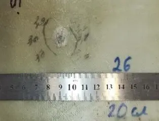
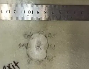
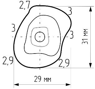
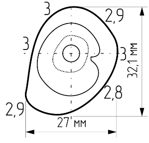
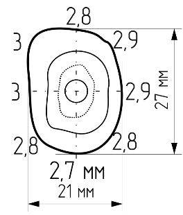
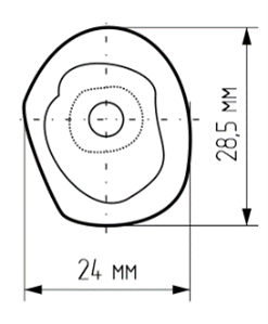
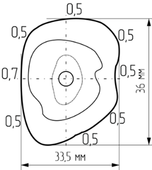
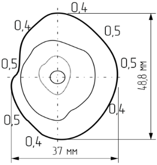
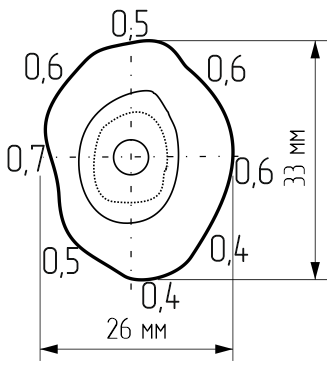
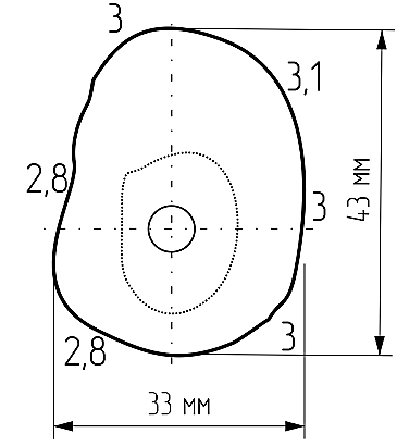
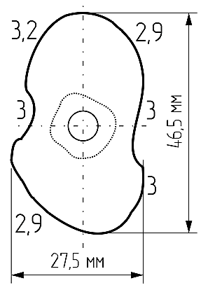
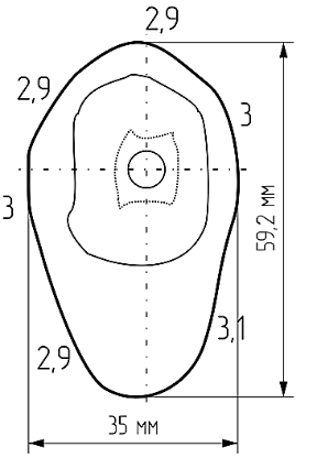
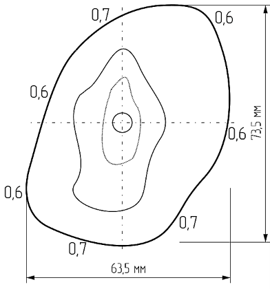
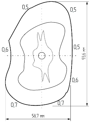
The ultrasonic inspection device KM ELISA GMIUC002-14 (Irkutsk National Research Technical University, Irkutsk, Russia) was used to assess internal damage. The device determined the damage boundaries and defect depth for each layer. The device detected laminations starting from a depth of 0.15 mm (thickness of one layer—0.2 mm). Control of the sample was carried out from the back and front sides of the multilayer plate. Table 1 shows the damage patterns of the plates at an impact speed of 884 m/s for four samples, No. 2–5. The maximum diameter of the through piercing (d) of the plate at a hammer speed of 884 m/s is equal to d = 5.72 mm, the maximum diameter of the lamination (dl) is equal to dl = 48.8 mm, which is 88% higher than the diameter of the piercing. Table 2 presents diagrams of plate damage at an impact of 346 m/s of three samples, No. 6–8. The maximum diameter of through penetration of the plate at a speed of striker 346 m/s is equal to d = 9 mm, the maximum diameter of lamination is equal to dl = 93.6 mm, which is 90% more than the diameter of penetration. The stratification area considerably exceeds the plate penetration area.
Table 1. Depth and dimensions of damages formed by an impact 884 m/s, detected by ultrasonic method and visual inspection.
|
№ Sample |
2 |
3 |
4 |
5 |
|---|---|---|---|---|
|
face |
 |
 |
 |
 |
|
back |
 |
 |
 |
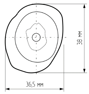 |
Table 2. Depth and dimensions of damages formed by an impact of 346 m/s detected by the ultrasonic method and visual inspection.
|
№ Sample |
6 |
7 |
8 |
|---|---|---|---|
|
face |
 |
 |
 |
|
back |
 |
 |
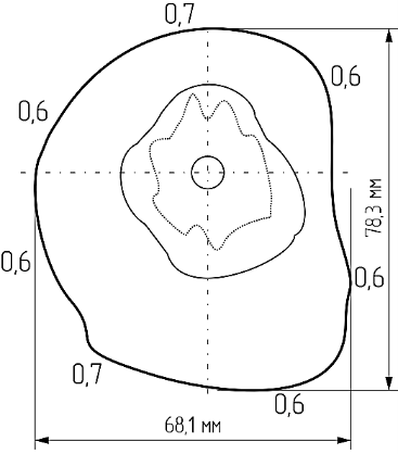 |
Figure 2 shows the results of non-destructive testing of sample No. 1 of a 20-layer fiberglass plate during high-speed impact. Defects on the front and back sides are presented, the boundaries of the defect detected by the ultrasonic method are marked with a dotted line along the depth of occurrence.
From the front side, the depth of the defect is determined at a depth of 2.9–3.4 mm, between the 13th and 16th layers of a multilayer plate made of CM, the area of maximum lamination is marked with a thick line and is 5.7 cm2.
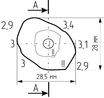
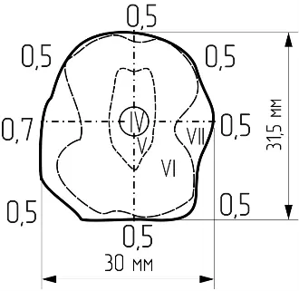
On the back side, the depth of the defect is determined by 0.5 mm, which corresponds to the location of the defect between the 18th and 19th layers, the area of maximum stratification is marked with a thick line and is equal to 8.2 cm2. On the front side of the plate, three zones of the interlayer defect (b) can be distinguished: I—a through hole equal to the diameter of the striker; II—multiple strand splitting region; III—the area of dissection, which can only be detected by ultrasound. Four zones can be distinguished from the back: zone IV—through hole; V—area of multiple splitting of threads; VI—visible stratification area, which can be detected visually; VII is the region of dissection detected by ultrasound.
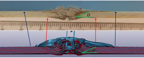
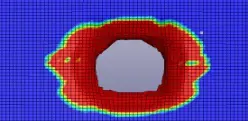
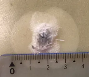
The results of numerical modeling are presented in Figure 3. The dimensions of the bundles obtained by numerical modeling in the LS-DYNA v195 software complex and experimentally under high-speed impact are shown. Dimensions of defects: maximum diameter of delamination d = 48.8 mm (ultrasonic flaw detection method, sample No. 3); diameter of the defect obtained by numerical modeling of d = 45 mm. The discrepancy is 7% (Figure 3a). Defect area and damage dimensions practically coincide (1–2% discrepancy), as shown in Figure 3b.
 |
|
|
(a) |
(b) |
Figure 3. Lamination dimensions in multilayer CM, obtained experimentally and numerically: (a) defect length, (b) defect area. Red arrows indicate the dimensions of complete destruction from the impact, blue arrows indicate the dimensions of the interlayer defect. The defect size difference is 7%.
Table 3 shows the results of numerical calculation of the damage area S (mm2) for different layering options of the 10-layer CM plate and the residual speed after impact at low-speed impact v (m/s).
Table 3. Results of numerical calculation of damage dimensions and residual velocity after impact.
|
Laying Fibers in the Layer |
№ 1 [0]10 |
№ 2 [±45]5 |
№ 3 [02/±452/902]02 |
№ 4 [0/90/±45]202 |
№ 5 [±30/90]330 |
№ 6 [0/90]10 |
|---|---|---|---|---|---|---|
|
S [mm2] |
1732.9 |
1589.1 |
1620.5 |
1546.7 |
1835.4 |
1839.6 |
|
v [m/s] |
310 |
315 |
312 |
316 |
309 |
307 |
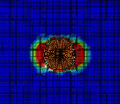
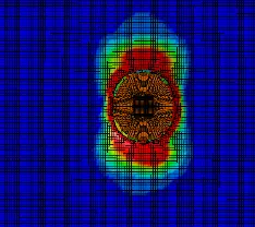
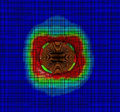
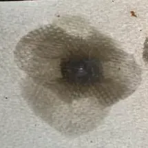
The relationship between the lamination area and the residual speed of the striker was obtained: the larger the lamination area, the lower the residual speed, and the lamination area depends on the angle of placement of fibers in the layer [14,17]. Figure 4 shows the results for determining the stratification area and the depth of the defect obtained from numerical modeling under high-speed impact. Defect area S = 6 cm2, interlayer defects are considered by layers. When combining the layers (from 1 to 5 layers) obtained by modeling (Figure 4a), we achieve good convergence with the experimental results (Figure 4b).
|
1–2 layers |
2–3 layers |
3–4 layers |
4–5 layers |
Experiment |
 |
 |
 |
 |
 |
|
(a) |
(b) |
|||
Figure 4. Numerical modeling of defect, comparison with experiment: (a) numerical modeling of defect by layers, (b) result of experiment.
The active thermography method is based on recording the temperature change of the object under external thermal excitation. The external heat source applied to the material may be halogen lamps, inductive coils, ultrasonic waves, or other thermal energy sources. Excitation causes a thermal response on the surface of the object, which is recorded by an infrared camera (IR) with subsequent processing of the obtained images. A general view of the IR imaging procedure using active thermography is shown in Figure 5.
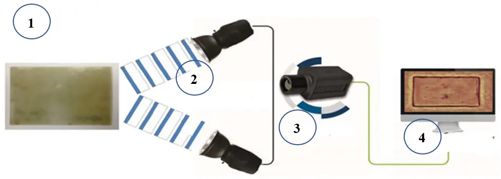
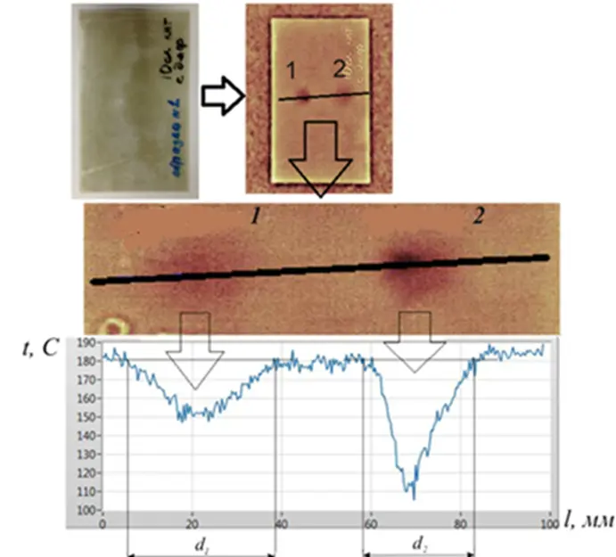
Four 800 W infrared halogen lamps (2) were used for thermal excitation at the control object (1). The object surface temperature dynamics are recorded using an IR camera (3) in the form of a sequence of its IR images (thermograms—(4)). Furthermore, the information obtained on temperature dynamics (4) is processed using image processing algorithms. This approach allows us to quantify the identified inhomogeneities, introduce objective criteria for the defects in the controlled area, and evaluate the parameters of the detected defects from the corresponding differences in brightness on the graph (peaks or recessions). Detection of delamination type defects and processing of results are shown in Figure 6.
The disadvantage of using the active thermography method is the need to ensure uniform heating of the surface under load, a highly contaminated or glossy surface creates interference and complicates the interpretation of the results. Since the heat wave is sharply attenuated in depth, therefore, the thickness of the controlled layer is usually limited to 10 mm. Also, in order to accurately determine the location of the damage, it is necessary to pre-calibrate the sample with a predetermined damage at a certain depth.
3. Conclusions
The results of a comprehensive study of internal defects in samples subjected to impact damage were obtained using diagnostic and numerical methods. To analyze interlayer defects in samples from KM after impact damage, a comprehensive control is used, which includes several methods of non-destructive testing: visual inspection, ultrasonic flaw detection, active thermography method, and comparison of the results with numerical modeling. All methods were independently and comprehensively evaluated for their effectiveness in detecting interlayer defects in multilayer composites. Each method has advantages in certain aspects, but practically none of them allow for comprehensive detection of all possible defects or damage. Stratification areas and the depth of defects are determined in various ways. With the help of visual inspection, the size of the damage on the back and front of the plates was determined. Using the ultrasonic flaw detection method, internal damage was assessed at a maximum depth of 3.4 mm. The dimensions of the bundles obtained by numerical modeling in the LS-DYNA v195 software system are shown, a comparison with experimental results is given. The active thermography method is integral, enabling control of the entire surface of the plate and making it comparable in efficiency to visual control. It has been found that the results from numerical modulation of interlayer defects and from non-destructive inspection of defects such as laminations, obtained by different methods, agree satisfactorily. The final result of detecting an interlayer defect depends not only on the size and nature of the defect but also on the technology of non-destructive testing and the laboratory equipment itself. Non-destructive testing technology depends on the actual conditions of testing, on the characteristics of instruments for non-destructive testing and flaw detection, the location of damage, the availability of structures and types of tested materials. All these factors should be taken into account when assessing the state of composite materials after dynamic loads.
Acknowledgments
The work was carried out within the framework of grant of the Republic of Buryatia No. 30-2025-008364.
Author Contributions
All authors made equivalent contributions to the preparation of the publication.
Ethics Statement
The study was conducted in accordance with the expert opinion of the intra-university commission of the export opinion of the East Siberian State University of Technology and Management (VSGUTU) of 24.07.2026.
Informed Consent Statement
Informed consent was obtained from all study authors.
Data Availability Statement
The data that support the findings of this study are openly available.
Funding
The work was carried out within the framework of grant RB No. 30-2025-008364.
Declaration of Competing Interest
The authors declare that they have no known competing financial interests or personal relationships that could have appeared to influence the work reported in this paper.
References
-
Wang X, Ma Y, Wang L, Qiu Z. Advances in the optimization design study for aircraft composite structure. Sci. Sin.-Phys. Mech. Astron. 2018, 48, 014602. DOI:10.1360/SSPMA2017-00043 [Google Scholar]
-
Towsyfyan H, Biguri A, Boardman R, Blumensath T. Successes and challenges in non-destructive testing of aircraft composite structures. Chin. J. Aeronaut. 2020, 33, 771–791. DOI:10.1016/j.cja.2019.09.017 [Google Scholar]
-
Mohamed MH, Wetzel KK. 3D Woven Carbon/Glass Hybrid Spar Cap for Wind Turbine Rotor Blade. J. Sol. Energy Eng. 2006, 128, 562–573. DOI:10.1115/1.2349543 [Google Scholar]
-
Salifu S, Desai D, Ogunbiyi O, Mwale K. Recent development in the additive manufacturing of polymer-based composites for automotive structures—A review. Int. J. Adv. Manuf. Technol. 2022, 119, 6877–6891. DOI:10.1007/s00170-021-08569-z [Google Scholar]
-
Zhang X, Zhao N, He C. The superior mechanical and physical properties of nanocarbon reinforced bulk composites achieved by architecture design—A review. Prog. Mater. Sci. 2020, 113, 100672. DOI:10.1016/j.pmatsci.2020.100672 [Google Scholar]
-
Bokhoeva LA, Rogov VE, Chermoshentseva AS. Stability of round defects such as delamination in structural elements taking into account transverse shear. Mod. Technol. Syst. Anal. Model. 2014, 4, 19–22. Available online: https://cyberleninka.ru/article/n/ustoychivost-kruglyh-defektov-tipa-otsloeniy-v-elementah-konstruktsiy-s-uchetom-poperechnogo-sdviga/viewer (accessed on 20 June 2026).
-
Senthil K, Arockiarajan A, Palaninathan R, Santhosh B, Usha KM. Defects in composite structures: Its effects and prediction methods—A comprehensive review. Compos. Struct. 2013, 106, 139–149. DOI:10.1016/j.compstruct.2013.06.008 [Google Scholar]
-
Chernushin VA, Rusakov DY, Kuryatin AA. Features of the research of the structure and assessment of the quality of composite materials by means of non-destructive testing techniques. J. Phys. Conf. Ser. 2021, 1758, 012033. DOI:10.1088/1742-6596/1758/1/012033 [Google Scholar]
-
Kuznetsov AO, Koshelnikov VS, Chernov LA, Budadin ON. Modeling of random geometric characteristics of inclusions in the material. J. Control. Diagn. 2020, 4, 40–45. DOI:10.14489/td.2020.04.pp.040‑045 [Google Scholar]
-
Karimbaev TD, Palchikov DS. Methods of non-destructive testing of aircraft engine parts and composite materials. Identification of the boundaries of admissibility of defects. Bull. Samara State Aerosp. Univ. 2014, 13, 96–105. DOI:10.18287/1998-6629-2014-0-5-1(47)-96-105 [Google Scholar]
-
Aniskovich VA, Budadin ON, Kozelskaya SO, Rykov AN. New technologies of non-destructive testing and technical diagnostics of structures made of composite materials. News Russ. Acad. Missile Artill. Sci. 2026, 1, 120–126. DOI:10.53816/20753608_2026_1_120 [Google Scholar]
-
Katunin A, Dragan K, Nowak T, Chalimoniuk M. Quality Control Approach for the Detection of Internal Lower Density Areas in Composite Disks in Industrial Conditions Based on a Combination of NDT Techniques. Sensors 2021, 21, 7174. DOI:10.3390/s21217174 [Google Scholar]
-
Katunin A, Wronkowicz-Katunin A, Dragan K. Impact Damage Evaluation in Composite Structures Based on Fusion of Results of Ultrasonic Testing and X-ray Computed Tomography. Sensors 2020, 20, 1867. DOI:10.3390/s20071867 [Google Scholar]
-
Bokhoeva LA, Rogov VE, Baldanov AB, Ivanov YN. Modeling of the optimal multilayer plate made of composite materials to reduce the speed after impact. Mech. Eng. Eng. Educ. 2022, 3–4, 3–11. Available online: https://www.elibrary.ru/download/elibrary_50206179_57669351.pdf (accessed on 20 June 2026).
-
Beklemysheva KA, Petrov IB. Modeling the destruction of hybrid composites under the influence of low-speed impact. Math. Model. 2018, 30, 27–43. Available online: https://ras.jes.su/mmod/s207987840001158-2-1 (accessed on 20 June 2026).
-
Lubov B, Vitaly R, Shunqi M, Anna C, Anatoly I, Alexander N. Buckling and Post-Buckling Behavior of the Delaminated Composite Plates. Adv. Mater. Sustain. Manuf. 2026, 3, 10003. DOI:10.70322/amsm.2026.10003 [Google Scholar]
-
Bokhoeva LA, Pnev AG, Filippova KA. Development of an algorithm for automatic processing of experimental results of samples from composite materials with defects. Bull. Kazan State Tech. Univ. Named After A.N. Tupolev 2010, 4, 10–16. Available online: https://www.elibrary.ru/download/elibrary_17846880_29460580.pdf (accessed on 20 June 2026).