Three-Dimensional Topography Prediction in Milling Medically Difficult-to-Process Materials: Mechanism, Modeling and Evaluation

Three-Dimensional Topography Prediction in Milling Medically Difficult-to-Process Materials: Mechanism, Modeling and Evaluation
Zhiwei Guo 1 Zhongling Xue 1 Tianyu Zhu 2 Dedong Yu 3 Lei Wang 4 Qinglong An 1,*
Received: 01 April 2026 Revised: 14 April 2026 Accepted: 08 May 2026 Published: 04 June 2026

© 2026 The authors. This is an open access article under the Creative Commons Attribution 4.0 International License (https://creativecommons.org/licenses/by/4.0/).
1. Introduction
With the rapid development of medical device manufacturing, the machining quality of key components in medical implants and surgical instruments is facing increasingly stringent requirements [1,2]. As the core raw materials of high-end medical devices, medically difficult-to-process materials determine the service performance and biocompatibility of implants, and their three-dimensional surface topography formed by milling is a key factor affecting friction characteristics, wear resistance, cell adhesion and long-term service life, so the accurate prediction and control of surface topography have essential theoretical and engineering necessity for improving the quality of medical components [3,4,5,6]. At present, the research on 3D topography prediction in milling such materials still faces problems, including unclear formation mechanism, incomplete consideration of modeling factors, and insufficient verification methods, which restricts the development and engineering application of high-precision topography prediction technology [7,8,9]. Driven by the demand for precision machining and surface quality control of medical key components, this review is motivated to systematically sort out the generation mechanism, modeling methods, and validation approaches of 3D surface topography in milling medically difficult-to-process materials, and provide a unified theoretical reference for breaking through the technical bottlenecks of topography prediction and realizing high-quality machining of medical difficult-to-process materials.
Initial methods for modeling machined surface topography relied solely on simple geometric analysis, but have since evolved to enable multiphysics coupled simulations [10,11,12]. Early surface topography modeling was based on ideal kinematics, treating the cutting edge trajectory of the tool as a circular arc or cycloid, and then calculating surface roughness through geometric superposition. For example, in 1991, El Baradie [13] established a surface roughness model for turning processes and analyzed the effects of process parameters such as cutting speed, feed rate, and tool tip radius on surface roughness using response surface methodology. Although this model can predict machined surface roughness, it ignores the effects of factors present in actual machining, such as tool runout and system vibration, and therefore has limited predictive accuracy. As research into machining processes has deepened, researchers have gradually incorporated factors such as tool runout [14,15], system vibration [16], tool deflection [17,18], and material springback [19] into surface topography prediction models. Meanwhile, numerical simulation methods have provided new tools for modeling 3D surface topography, and researchers have begun to employ methods such as the Z-map algorithm [20,21,22] and Boolean operations [23,24] to simulate 3D surface topography with greater precision. Furthermore, the widespread adoption of five-axis machining technology in recent years has driven the development of surface topography modeling toward multi-factor [25] and multi-scale [26,27] approaches, resulting in the formation of a comprehensive modeling framework.
To date, several review articles have summarized the progress and future trends in modeling the surface topography of metal machining, providing a theoretical framework for subsequent research in this field. For example, Pawlus et al. [28] conducted a detailed analysis of surface topography generation models for turning and milling, exploring various methods including analytical, experimental, and numerical approaches. They further analyzed the effects of tool geometry, cutting parameters, and vibration states on surface texture, clearly identifying research directions to improve the accuracy and consistency of surface texture modeling during machining. Sun et al. [25] provided a comprehensive review of research on milling surface topography modeling, analyzed the structural mechanisms of surface topography, and investigated the surface topography of complex components based on multiple dimensions, including tool geometry, process parameters, dynamic factors, and material properties. Yue et al. [29] focused on the impact of milling surface integrity on part fatigue strength and wear resistance, providing a detailed review of how different cutting conditions affect surface topography and revealing the mapping relationship between machining conditions, surface integrity, and part performance during the machining process. Zhang et al. [30] summarized the formation mechanisms of surface roughness in the field of ultra-precision machining, reviewed various factors affecting surface roughness, and particularly emphasized the significance of spindle vibration and material elastic deformation in high-precision machining. Building on this foundation, Manjunath et al. [31] further focused on the generation of ultra-precision machined surfaces and the prediction of surface roughness, discussing and exploring future directions in this field through artificial intelligence and digital solutions, particularly the real-time application of these technologies to address practical challenges in ultra-precision machining. Liu et al. [32] conducted a modeling review addressing surface roughness and burr formation in micro-milling scenarios. They conducted an in-depth analysis of the effects of size effects, minimum cutting thickness, tool wear, and other factors on machined surface quality, and summarized the challenges and opportunities for achieving high surface quality during the micro-milling process.
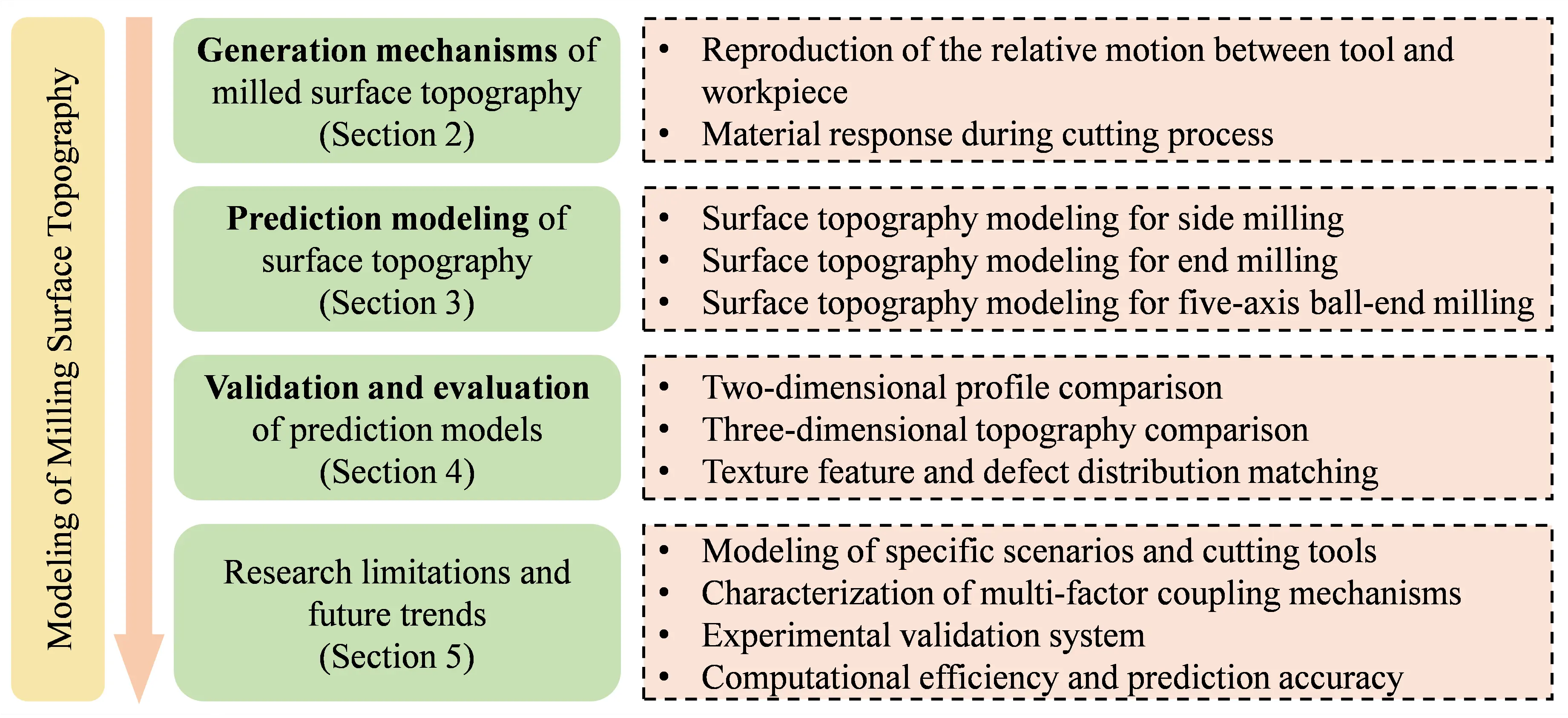
Existing reviews on milled surface topography prediction mostly focus on isolated aspects such as geometric modeling or roughness evaluation, with few constructing a systematic, full-chain analysis framework for three-dimensional topography prediction spanning formation mechanism, multi-process modeling, and validation evaluation. Notably, targeted sorting of the unique topography formation rules and modeling challenges across different milling processes for difficult-to-machine materials remains scarce. Against this background, this review fills these gaps by establishing a unified analysis framework integrating the coupled mechanism of tool-workpiece kinematics and material dynamic response, the classification and comparison of multi-process modeling methods, and the multi-dimensional validation and evaluation system, as shown in Figure 1. Compared with previous studies, this work innovatively distinguishes the topography formation characteristics of side milling, end milling, and five-axis ball-end milling, clarifies the adaptability and limitations of kinematic models and multi-physics coupling models under varying working conditions, and further identifies the key bottlenecks restricting the engineering application of prediction models, providing clear, targeted guidance for the development of high-precision, high-efficiency topography prediction technologies and precision milling of difficult-to-machine materials.
This review was conducted following systematic bibliometric analysis standards. The literature retrieval was performed in the Scopus, Web of Science, and CNKI databases using the search keywords “medical difficult-to-process materials”, “milling”, “3D surface topography”, “generation mechanism”, and “prediction modeling”, with the search time range set from 1990 to 2026. The inclusion criteria cover peer-reviewed journal articles and authoritative reviews focused on milling surface topography modeling, studies involving difficult-to-machine materials for medical applications, and papers with a clear modeling mechanism, method, or validation. The exclusion criteria include duplicate publications, conference abstracts without complete data, and studies irrelevant to 3D topography prediction. More than 140 core literatures were finally included after screening, and they were categorized by modeling method, machining process, and evaluation index for systematic analysis.
2. Generation Mechanism of Surface Topography in Milling Medically Difficult-to-Process Materials
The 3D surface topography of medically difficult-to-process materials is determined by the coupled effect of kinematic behavior and material dynamic response during milling. This chapter first analyzes the reproduction rule of tool-workpiece relative motion, and then reveals the modification mechanism of material deformation and interfacial interaction on surface topography, laying a mechanical foundation for the subsequent modeling research.
2.1. Reproduction of the Relative Motion Between the Tool and Workpiece
The essence of surface topography in milling is the reproduction of the relative motion trajectories between the tool cutting edges and the workpiece surface [33,34]. During the milling process, the tool engages in cutting action with the workpiece via a preset motion. The continuous superposition of the cutting edge trajectories leaves residual textures with specific geometric characteristics on the workpiece surface. The formation of surface topography abides by the fundamental principles of kinematics and geometry. Differences in the kinematic characteristics of various milling processes determine the distinct periodicity, directionality, and complexity of the surface topography [35].
2.1.1. Side Milling
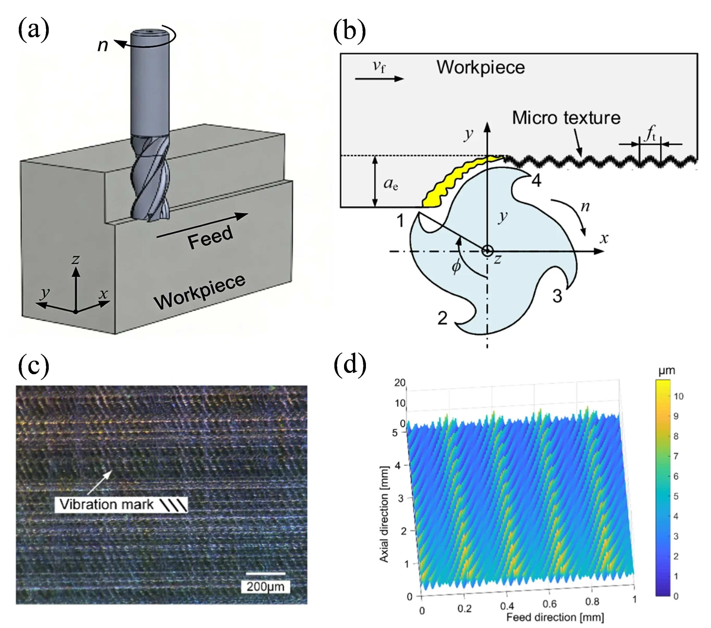
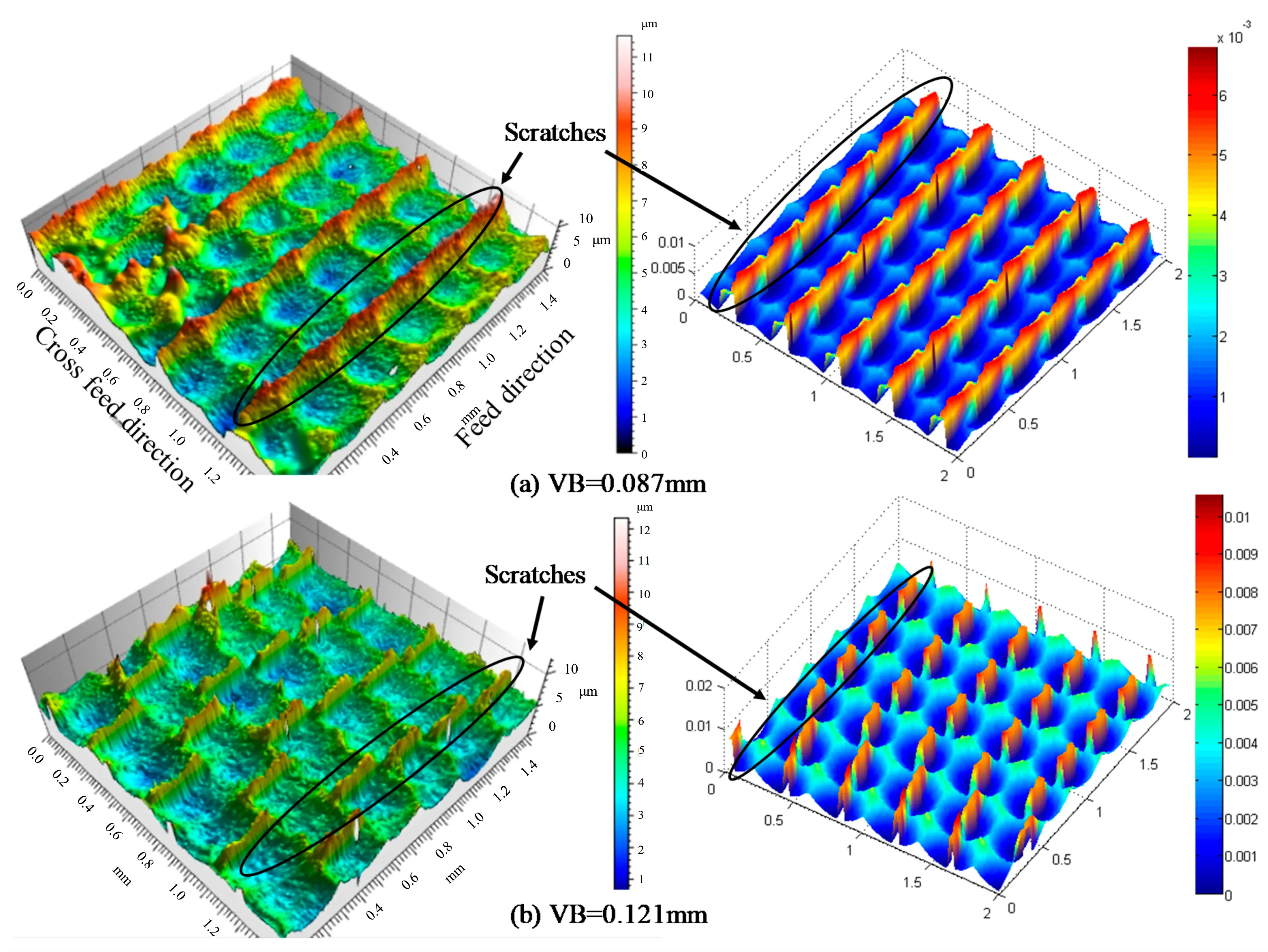
Side milling, also known as peripheral milling, is a machining method that employs the peripheral edges of a cylindrical milling tool as the main cutting edges, and achieves material removal through the high-speed rotation of the tool and the feed motion of the workpiece [36,37]. Under ideal machining conditions without vibration and tool eccentricity, the motion trajectory of each cutting edge is a cycloid generated by the combination of the tool’s high-speed rotation around its own axis and its translation along the feed direction. The cycloidal trajectories of adjacent cutting edges successively leave arcuate marks on the workpiece surface. After the tool completes one full revolution, the superposition of all cutting-edge trajectories forms parallelly arranged striped surface textures, as illustrated in Figure 2 [38]. Figure 2a presents the 3D view of side milling topography generation. Figure 2b shows the cross-sectional profile and residual height. Figure 2c displays the measured actual surface topography. Figure 2d provides the simulated topography for model verification.
In early studies, to reduce modeling complexity, researchers approximated side milling trajectories as circular arcs to predict surface topography [39]. Although this simplified method can reflect the basic characteristics of the machined surface topography to a certain extent, it deviates significantly from the complex tool trajectories in actual machining [40,41]. With the deepening of research, accurate models for predicting side milling surface topography have been gradually improved. For example, Zhang et al. [42] developed a model of milled surface topography based on the principle that the true tooth path curve at the cutting contact point can be approximated by a circle of curvature, which is more accurate than the circular trajectory of the milling tooth. Miao et al. [43] explained the side milling mechanism from a kinematic perspective, pointing out that the periodic superposition of cutting edge trajectories is the core mechanism for the formation of regular surface textures. This mechanism determines that side milling surface textures have high directional consistency and also endows them with strong regularity and predictability [44].
2.1.2. End Milling
Surfaces generated by milling with an end mill tool include not only side faces but also end faces. The side faces are produced by the peripheral cutting edges, while the end faces are formed by the bottom cutting edges and the transition edges connecting the bottom edges and peripheral edges, as shown in Figure 3a,b [45]. The generation mechanism of the 3D topography of end-milled surfaces is completely different from that of side-milled surfaces. Since the bottom edges and transition edges generate the end face of the machined part, any point on the end face is passed by the tool twice in succession, namely front-cutting and back-cutting [46,47]. As a result, the end-face topography exhibits more complex textures than those in side milling. The corresponding front- and back-cutting textures on the end face are shown in Figure 3c,d [45]. Unlike side-milled surfaces, the topography of the end face depends not only on the motion trajectories of the cutting edges but also on the reproduction of the geometric shape of the transition edges. Therefore, to accurately predict the 3D topography, the prediction model must additionally take into account the geometry of the end cutting edges as well as the front- and back-cutting motions during the milling process.
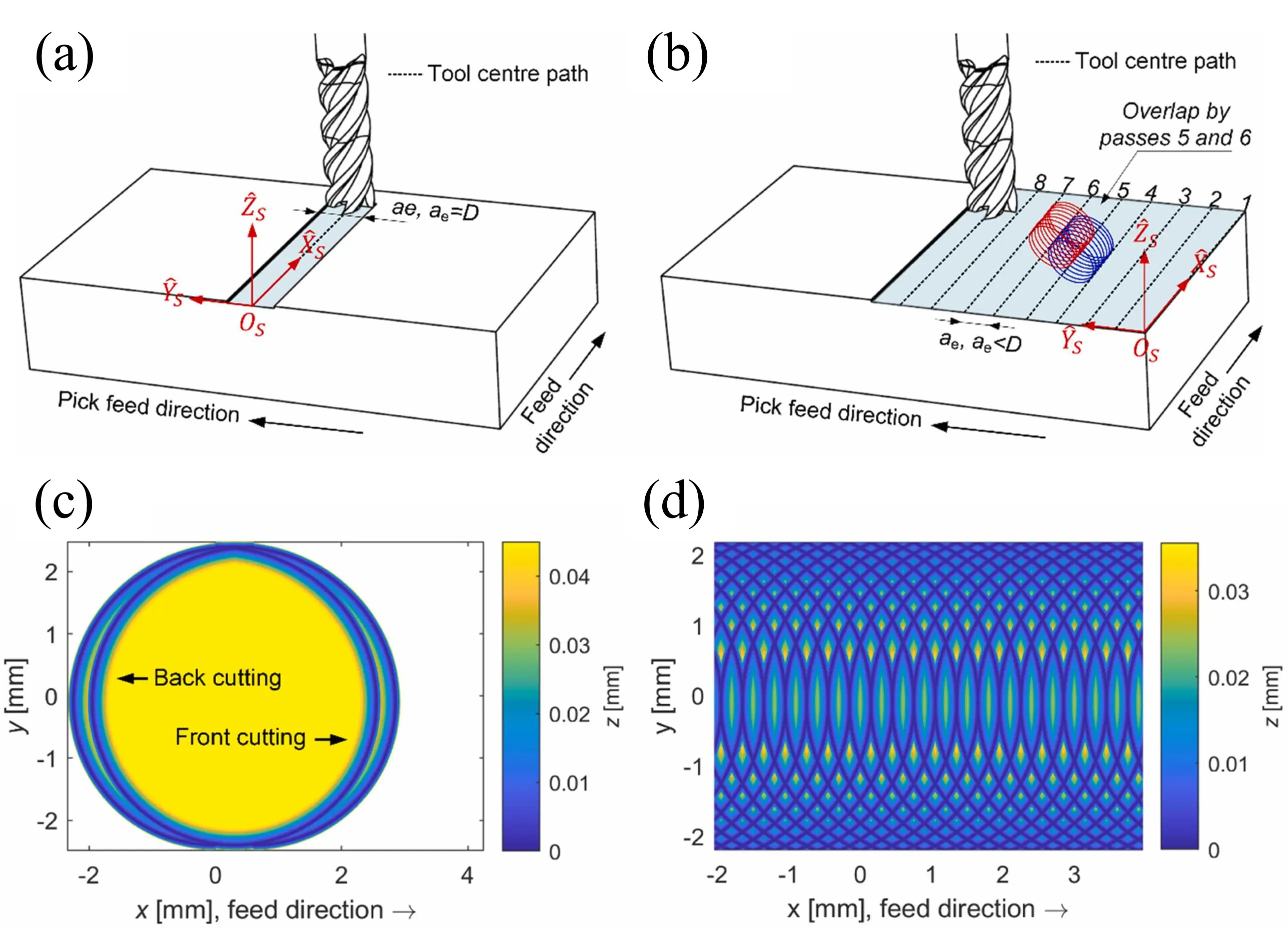
Figure 3. Generation of surface topography in flat-end milling [45]. (a) A single milling pass; (b) Multiple milling passes; (c) 3D topography of end-milled surface within one rotation cycle; (d) Final 3D topography of the entire target area after the end mill has completely passed through the area.
Baek et al. [48] established a fundamental surface roughness model for flat end milling, which comprehensively considered cutting forces, insert runout, and vibration displacement, achieving an initial breakthrough from static geometric description to dynamic coupling. On this basis, they further analyzed the effects of runout and feed rate, and proposed a method for determining the optimal feed rate [49]. Subsequently, Ryu et al. [47] put forward the conical surface superposition theory from a geometric perspective, revealing that the surface texture is formed by the superposition of conical surfaces generated by the rotation of the end cutting edges, and pointing out the existence of the secondary cutting phenomenon, thus constructing a relatively complete initial geometric model. Cai et al. [45] developed a novel 3D topography prediction model for the bottom surface in end milling, which fully accounts for complex machining conditions including tool radial and axial runout, installation errors, tool-workpiece vibration, tool deflection, front- and back-cutting motions, and overlapping multi-pass tool paths. Franco et al. [50] introduced statistical analysis methods to address the randomness of runout errors, while conducting an in-depth investigation into the influence mechanism of secondary cutting on surface quality. Wang et al. [51] proposed an efficient forward-inverse solution algorithm, which significantly improves computational efficiency via the swept surface method and Newton-Raphson iteration, enabling it to meet the simulation requirements of large-diameter tools and large-scale workpieces.
2.1.3. Five-Axis Ball-End Milling
Five-axis milling is the core process for machining complex curved parts. Through the simultaneous movement of three linear axes and two rotary axes, it endows the tool with highly flexible posture adjustment capability [52]. Five-axis milling using ball-end mills is a common method for machining complex surfaces. The formation mechanism of its surface topography is an integrated upgrade of side milling and end milling mechanisms, which mainly stems from tool trajectory optimization and cutting posture adaptation brought by multi-axis coordination, showing more complex reproduction characteristics [53,54]. A ball-end mill consists of a ball-end helical edge section and a cylindrical helical edge section, which can be regarded as a combination of side milling and end milling, as shown in Figure 4 [55]. Side milling generates the side surface along the peripheral edges, while end milling forms the end surface using a chamfer or fillet that connects the end edges to the peripheral edges. Therefore, side milling and end milling with solid carbide end mills can be considered as special cases of ball-end milling [56,57].
Surface topography modeling for five-axis ball-end milling originated from the scallop height generation model established by Chen et al. [58]. This model systematically elucidated the mechanism underlying the formation of scallop heights induced by path and feed intervals, laying the theoretical foundation for predicting surface topography in five-axis ball-end milling. Subsequently, Arizmendi et al. [59] introduced a numerical solution method based on Chebyshev expansion, which transformed transcendental equations into polynomial forms and avoided the dependence of traditional iteration on initial values, thus improving computational stability. To break through the limitations of pure geometric modeling, Layegh and Lazoglu [60] developed a three-dimensional simulation model considering feed rate, tool inclination angle, and tool runout. By extracting the convex hull of the cycloidal motion of cutting edges on the plane perpendicular to the feed direction to reconstruct the surface envelope, they revealed the influence laws of inclination angle and lead angle on three-dimensional surface roughness parameters. To meet the requirements of complex surface machining, Zhang et al. [57] derived the analytical form of the tool swept envelope using homogeneous coordinate transformations and combined it with the Z-map discretization method to predict the surface topography and roughness of sculptured surfaces. In addition, to improve computational efficiency, Xu et al. [61] proposed an accurate interpolation method based on swept surfaces and systematically analyzed the effects of spindle speed, feed rate, inclination angle, path interval, tool runout, and other factors on surface topography. In recent years, research perspectives have been further extended to the microscopic scale and actual machining conditions. Dong et al. [55] introduced cutting edge micro-geometry and the minimum chip thickness effect into their modeling. Biondani et al. [62] constructed a surface generation model based on real cutting edge topography, while Wang et al. [63] achieved an accurate prediction of surface topography in thin-walled component machining by incorporating cutting vibration into the simulation model.
2.2. Machined Material Response During the Milling Process
The generation of milling surface topography does not depend solely on the ideal reproduction of the relative motion trajectories between the tool and the workpiece. The dynamic response of the workpiece material under cutting loads also modifies these trajectories. Essentially, this process involves the mechanical, physical, and chemical behaviors of the material under the effects of cutting forces, cutting heat, and interfacial interactions, which directly cause the actual surface topography to deviate from the theoretical predictions based on geometric trajectories.
2.2.1. Elastic Deformation Induced by Milling
During the milling process, the material undergoes both elastic and plastic deformation under the action of the cutting tool, whose specific characteristics are directly governed by the mechanical environment in the cutting zone [64,65]. As shown in Figure 5a, the third shear zone is the main region where elasto-plastic deformation occurs. The extrusion and friction between the tool flank face and the machined surface induce microstructural changes in the material, a phenomenon that has been validated in the milling of difficult-to-cut materials [66,67]. Plastic deformation corresponds to irreversible plastic flow, characterized by grain slip and elongation, which results in permanent topographical changes. In contrast, elastic deformation is a temporary deviation in shape that can partially recover after unloading. The coupled behavior of these two deformation mechanisms has been explained by the molecular mechanical friction theory, as illustrated in Figure 5b [67]. Under intermittent cutting conditions, the periodic variation of cutting forces causes dynamic fluctuations in the deformation depth. For high-hardness materials, work hardening induced by plastic deformation often further complicates the subsequent cutting process. Since the height difference caused by elasto-plastic deformation directly determines the microscopic undulations of the residual surface topography, its evolution not only affects surface roughness but also alters the tool-workpiece contact state in subsequent cutting passes, thereby imposing high requirements on the accuracy of topography modelling [68,69].
Regarding the intrinsic relationship between cutting deformation and surface topography, representative research achievements have emerged across multiple dimensions in recent years. As shown in Figure 5c, the elastic deflection of thin-walled components under milling loads directly alters the instantaneous chip thickness and the tool-workpiece contact state, which are core factors affecting surface topography formation. To address the dynamic changes in tool-workpiece contact, Chen et al. [70] distinguished between single-tooth and double-tooth cutting modes using discrete micro-cutting disk elements, introduced workpiece deflection to modify the instantaneous chip thickness, and established a force-deformation coupled error prediction model via an iterative strategy. The average prediction errors of the model were 11.8% and 10.5% for single-tooth and double-tooth milling, respectively. Wan et al. [71] realized efficient estimation of the positioning errors of complex structural surfaces through 3D irregular voxel modeling. As illustrated in Figure 5d, the elasto-plastic deformation behavior of the workpiece surface in ball-end milling reshapes the three-dimensional topography through coupled plastic flow and elastic recovery processes. Chen et al. [72] proposed the concept of the “effective cutting edge” and integrated geometric errors such as machine tool perpendicularity and spindle dynamic balance into a multi-coefficient matrix to quantify their effects on surface roughness, achieving a low average relative prediction error of 4.59%. At the computational level of elasto-plastic deformation, Liu et al. [66] combined Kragelski’s friction theory with Hertzian elastic contact theory to establish a quantitative relationship among plastic deformation depth, elastic recovery height, and cutting force. For intermittent cutting, Liu et al. [66] further analyzed the characteristics of the contact phase, constructed a residual height model, and introduced the Johnson-Cook (J-C) constitutive equation to calculate material flow stress. The maximum prediction error of the model was 9.19%, with an average error of 6.33%. In addition, the variable stiffness finite element model proposed by Budak et al. [73] and the unified cutting force model established by Chen et al. [74] have collectively improved the cutting deformation modeling framework applicable to various machining conditions.
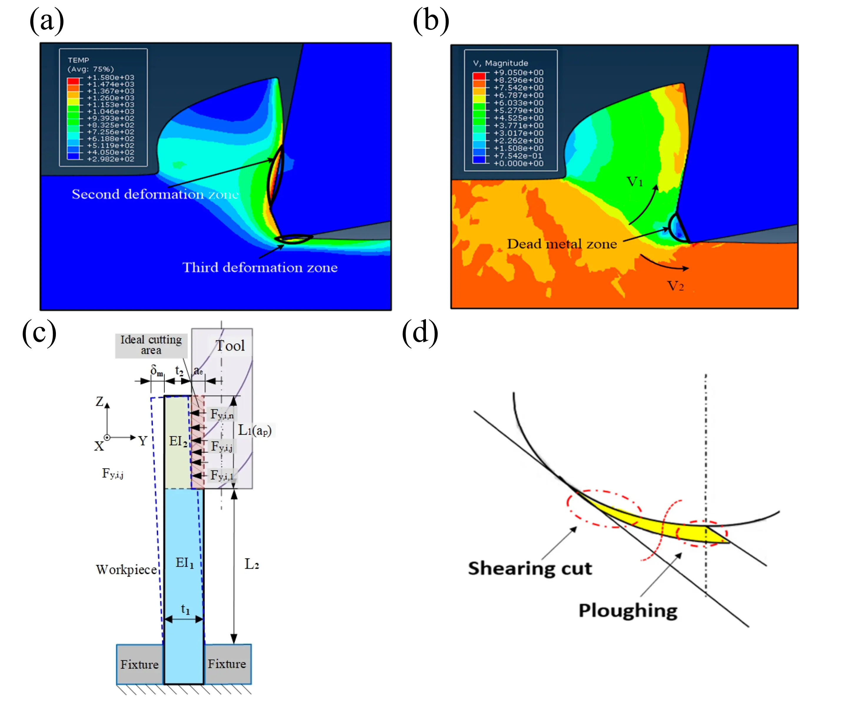
Figure 5. Elastic-plastic deformation of the workpiece surface in milling. (a) Metal cutting deformation zone [67]; (b) Formation mechanism of elastic and plastic deformation resulting from cutting force [67]; (c) Deformation of thin-walled parts [70]; (d) Elastic-plastic deformation of the workpiece surface in ball-end milling [75].
2.2.2. Interfacial Interactions Among Tool, Workpiece, and Chip
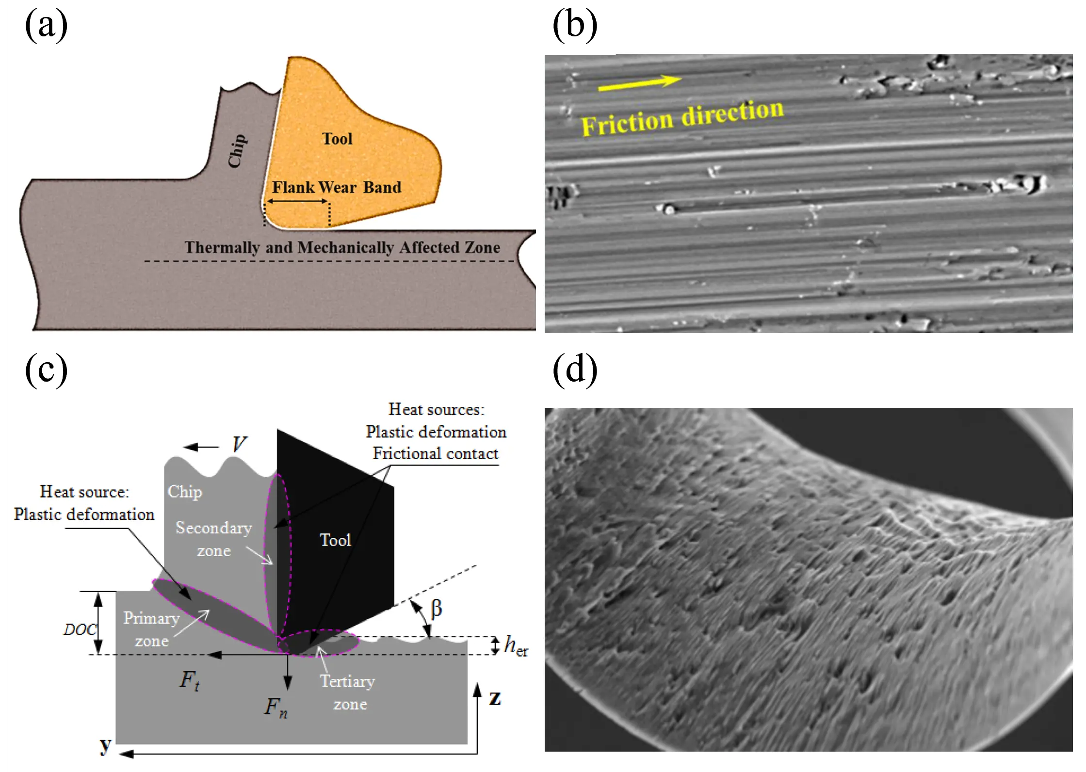
In the milling process, the interfacial behavior between the cutting tool, workpiece, and chips is not merely mechanical contact, but a complex process involving the interaction and coupling of mechanical, thermal, and chemical factors [76]. This coupled effect directly modifies the effective geometry of the tool and largely governs the material removal mode. The evolution of interfacial friction conditions, thermal softening effect, and chemical wear will disturb the stability of the cutting process, thereby influencing cutting force distribution, chip morphology, and tool profile, and ultimately leaving characteristic imprints on surface roughness, waviness, and residual stress distribution, as illustrated in Figure 6a [77].
For instance, Wu et al. [78] found, through high-speed internal-cooling helical milling experiments, that the friction coefficient at the bottom cutting edge significantly influences the distribution of cutting forces and cutting heat, thereby determining the amplitude of surface profile fluctuations. A study by Hassanpour et al. [77] on AISI 4340 steel showed that surface roughness increases sharply when the wear at the flank-workpiece interface exceeds 0.4 mm, which requires topography modeling to take into account the differences in friction conditions between the rake face and the flank face. From the perspective of thermo-mechanical coupling, Jiang and Song [79] pointed out that the dynamic feedback of “deformation-induced heat generation—thermal softening—property variation” directly affects the generation of surface profiles. Through dry milling experiments with aluminum alloy 6061, Wang et al. [80] demonstrated that thermal softening of the material caused by friction between the tool and the workpiece affects the integrity of the machined surface, as illustrated in Figure 6b–d. A study by Löschner et al. [81] based on the Johnson-Cook constitutive model further supported this conclusion. In the machining of Ti6Al4V, small changes in thermal softening parameters can cause temperature fluctuations of up to ±7.3% in the cutting zone and even trigger the transition of chip morphology from continuous to serrated, thus altering the formation mechanism of surface topography. In addition, interfacial chemical interactions often introduce time-varying effects through the evolution of tool wear. Liu et al. [82] found that the periodic detachment of built-up edge (BUE) during the cutting of Ti6Al4V leads to an increase in surface burrs. Wu et al. [83] indicated that high-temperature oxidation can modify the tool geometry and interfacial friction coefficient, and the time-dependent nature of these factors requires topography models to have time-varying adaptability. Meanwhile, in a study on the micro-milling of additively manufactured titanium alloys, Khaliq et al. [84] found that abrasive wear caused by material adhesion under dry cutting conditions significantly degrades surface quality. The research by Zawada-Michałowska et al. [85] further confirmed that cutting parameters indirectly affect the distribution characteristics of residual stress through interfacial interactions.
3. Modeling 3D Surface Topography in Different Milling Processes
On the basis of the formation mechanism, this chapter focuses on the 3D topography modeling methods of medically difficult-to-process materials under different milling processes. It will elaborate on the modeling characteristics of side milling, end milling, and five-axis ball-end milling in turn, and compare the adaptability of models considering different influencing factors.
3.1. Modeling 3D Surface Topography in Side Milling
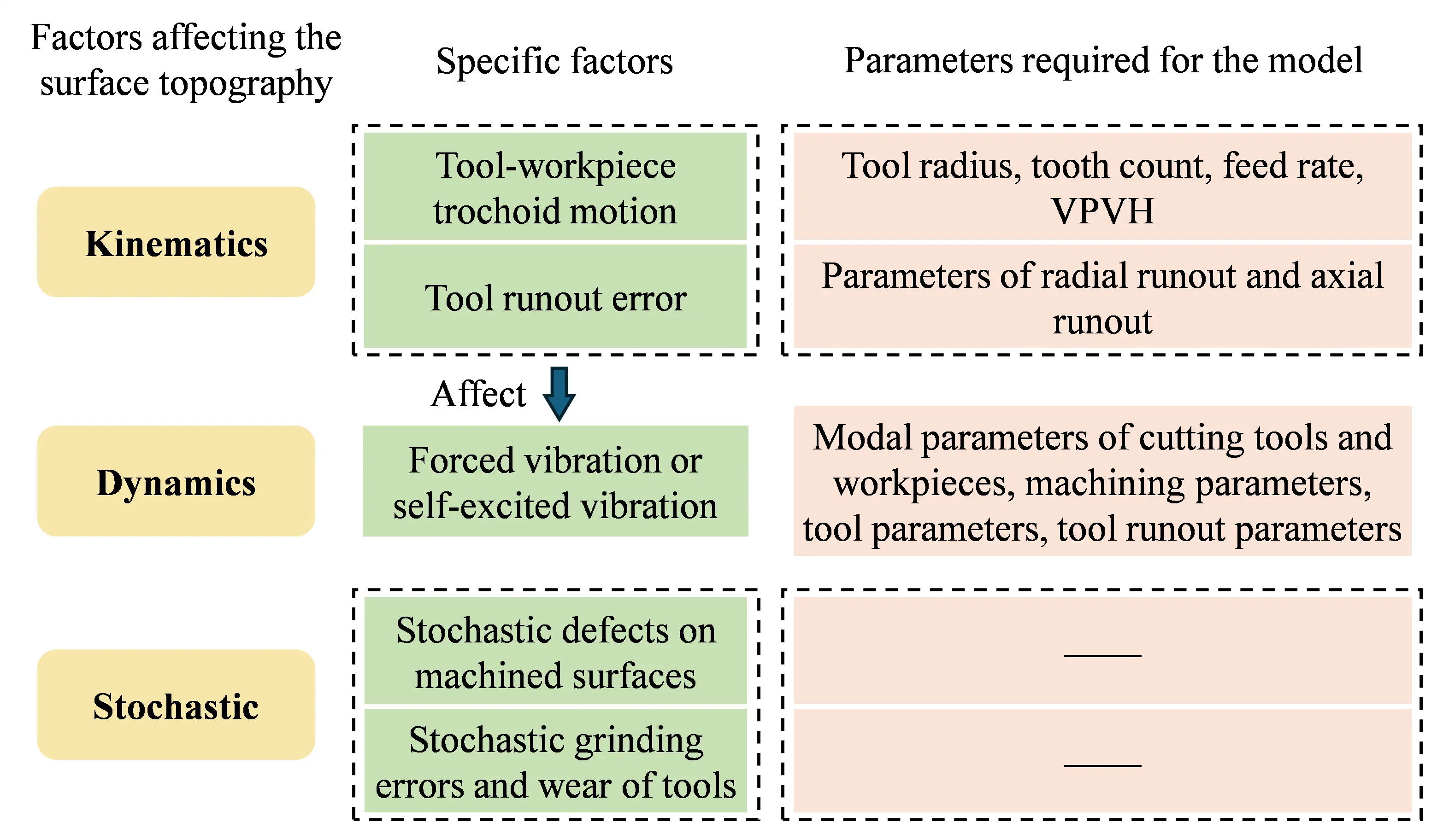
The formation of side-milled surfaces arises from the interference between the tool motion trajectory and the workpiece. Consequently, all factors that affect the motion trajectory will also influence the surface topography. The factors governing the machined surface topography and their corresponding parameters are summarized in Figure 7. To achieve an accurate prediction of side-milled surface topography, it is essential to take into account as many of the factors shown in Figure 7 as possible. It is worth noting that tool runout influences surface topography not only at the kinematic and geometric level but also affects milling forces and milling stability [86]. Therefore, tool runout must also be incorporated when solving for vibration displacements. However, the minimum chip thickness effect (material springback) caused by the cutting edge radius does not need to be considered in conventional milling surface topography modeling. This is because the feed rate used in milling (e.g., feed per tooth ft > 0.02 mm/z) is considerably larger than the minimum chip thickness required for actual chip formation. The minimum chip thickness effect only needs to be addressed in micro-milling (where feed per tooth ft is as low as 0.25 μm/z [87,88]) or single-point diamond ultra-precision turning (where feed per revolution f is only 0.25 μm/r [89]). A review of models considering different categories of influencing factors is provided in the following sections.
3.1.1. Models Considering Only Kinematic Factors
Regarding kinematic factors, David et al. [90] conducted experiments to analyze the effect of tool eccentricity on tool vibration and examined its impact on workpiece surface morphology, as shown in Figure 8. Arizmendi et al. [91] extended their earlier model [92] to include manufacturing errors in the tool itself, such as deviations of the actual tooth radius from the nominal radius. Based on their geometric model [91], Arizmendi’s team [93] identified tool radial runout parameters using the axial positions of heterogeneity bands in optical microscope images of side-milled surfaces.
Later, Buj-Corral et al. [94] considered the effect of tool helix angle on heterogeneity bands, finding that larger helix angles result in narrower axial widths of these bands. Notably, these researchers [91,92,93,94] simplified the tool motion trajectory to a circular arc rather than using the precise trochoidal motion. Krüger and Denkena [95] identified tool radial runout parameters based on milling force signals and then simulated surface topography using these parameters. Urbikain and López de Lacalle [96] developed a geometric model to predict the surface topography of tilted milling with circular cutters, considering tool geometry, machining parameters, tool orientation angle, and radial runout length. Urbikain Pelayo et al. [97] later established a geometric model for side-milled surface roughness using cylindrical cutters, accounting for variations in tool geometry and runout along the tool axis. However, these models did not consider system vibrations and primarily focused on predicting average roughness or its axial distribution. Additionally, few studies have predicted 3D surface topography and validated it with experimentally measured 3D topography.
3.1.2. Models Considering Dynamic Factors
Vibration displacement during milling affects surface topography and must be considered in its prediction. Arizmendi et al. [98] incorporated tool vibration displacement measured by displacement sensors into their side-milled surface topography prediction model, but the model did not account for tool runout. Denkena et al. [99] developed a surface topography prediction model that considered forced tool vibration, but the vibration displacement was derived from measured cutting forces, and the 3D topography model still ignored tool runout. Both methods require additional equipment, such as laser displacement sensors or force sensors, making them cumbersome. A more general approach to obtaining vibration displacement is through time-domain milling simulation models.
Ismail et al. [100] considered self-excited vibration, tool radial runout, and tool wear, finding that significant tool wear (VB = 0.3 mm) reduces the maximum height of the 2D surface profile in the feed direction. However, their model assumed a constant tool wear value across different axial heights and oversimplified the runout model by directly adding runout values to calculate cutting thickness, without considering the tool helix angle in the cutting force model. Elbestawi et al. [101] considered forced vibration, tool radial runout, and tool wear but assumed a helix angle of 0 when solving vibration displacement. Most of these studies validated surface topography using optical microscope images, which lack height information. Montgomery and Altintas [102] proposed a model to simultaneously predict milling forces and surface topography, calculating cutting thickness based on the tool’s trochoidal motion and considering self-excited vibrations of the tool and workpiece, but the model ignored tool runout. Artetxe et al. [103] developed a topography prediction model that included tool runout, thin-walled workpiece deflection under cutting forces, and variations in radial cutting width, but they did not account for system vibrations. Zhuo et al. [104] considered forced vibration and material removal effects in their side-milled 3D topography model, but the forced vibration displacement was derived from measured cutting forces. Omar et al. [105] considered tool radial runout, tool tilt, forced vibration, and tool wear (assumed constant across axial heights). However, their cutting force model was oversimplified, excluded self-excited vibrations, and was unsuitable for unstable machining conditions, and it did not fully account for tool runout. Additionally, the 3D surface roughness shown in Figure 9 contains information on both height and width, enabling a more accurate and detailed prediction of the effects of tool vibration [106].
3.1.3. Side-Milled Surface Profiles in Unstable Regions
Regarding surface profiles during chatter, Grossi et al. [107] explained the relationship between the spatial and frequency domains of 2D surface profiles and the time-domain frequency spectrum of milling indicators for 0° helix angle cutters without tool runout. However, their model only applies to single-degree-of-freedom (y-direction) systems and fails when flexibility exists in the feed direction (x-direction). Stepan et al. [108] analyzed the power spectrum of optical microscope images of machined surfaces under no vibration, forced vibration, and chatter using 2D FFT but did not develop a 3D topography prediction model.
Most studies focus on constant pitch and constant helix (CPCH) cutters, with limited research on variable pitch or variable helix (VPVH) cutters. Niu et al. [109] proposed a model for milling stability, surface roughness, and surface location error for VPCH cutters, including tool radial runout. Yang and Liu [110] predicted 3D surface topography for VPVH cutters, but their forced vibration differential equation relied on measured cutting forces, oversimplifying vibration displacement prediction. Their 3D topography predictions were only compared to a single microscope image, lacking height information.
In summary, existing literature predominantly focuses on 2D profiles or line roughness Ra for CPCH cutters, with limited research on predicting and validating 3D surface topography for VPVH cutters. Existing models also fail to comprehensively consider all factors affecting side-milled surface topography.
3.2. Modeling 3D Surface Topography in End Milling
Modeling the 3D surface topography in end milling involves two main tasks, predicting the motion trajectory of end cutting edges in the time domain and reconstructing 3D topography based on the end cutting edge trajectory. To establish an accurate surface topography prediction model, the geometric shape of the tool must be considered first. In addition, factors affecting the tool motion trajectory should be considered as comprehensively as possible, such as front and back cutting, tool runout, system vibration, and tool deflection. Among them, tool runout includes radial runout and axial runout of the tool tip. It is worth noting that the deflection deformation of the tool under milling forces, especially the deflection angle, has a particularly significant influence on surface topography. It alters the 3D surface topography by altering the relative intensities of front and back cutting [47]. Therefore, it must be considered in the modeling process.
3.2.1. End Milling
For conventional end milling, Melkote and Thangaraj [111] proposed a kinematic model predicting floor surface topography, considering tool runout, radial rake angle, and front- and back-cutting. Melkote et al. [46] later incorporated tool deflection angles induced by cutting forces, finding that 2D surface profiles strongly depend on back-cutting, which in turn depends on tool deflection angles. However, their cutting force model ignored self-excited vibrations, and the deflection angle was oversimplified by vector synthesis of feed and vertical feed displacements. Additionally, they only predicted 2D profiles, not 3D topography. Ryu et al. [47] developed a 3D topography simulation model considering tool runout, front- and back-cutting, and tool deflection, observing roughness variations in the step-over direction. However, their cutting force model ignored surface regeneration effects and tool runout, and the floor topography prediction model did not account for system vibrations.
3.2.2. Face Milling
Face milling floor surface formation principles are similar to end milling. Tapoglou et al. [112] developed a kinematic simulation model for face milling surfaces and cutting forces based on Boolean operations between tool and workpiece motion trajectories, but the model only considered front-cutting. They compared simulated and measured 2D profiles of the surface centerline but did not predict or measure 3D topography. Horava et al. [113] developed a 3D topography simulation model for face milling (shown in Figure 10) based on discrete and one-dimensional line interpolation, considering tool runout, front-cutting, and back-cutting, but the model ignored vibrations and tool deflection. Lazkano et al. [114] proposed a face milling floor topography prediction model consisting of a kinematic profile considering feed, front-cutting, and back-cutting, and a random profile obtained by high-pass filtering experimentally measured 2D profiles. The 3D profile was reconstructed from all cross-sectional 2D profiles in the step-over direction. Hadad and Ramezani [115] generated specific patterns on the floor surface by tilting the workpiece and spindle head at special angles and planning milling paths. They also developed a surface texture simulation model (lacking height information) but only considered tool-workpiece feed motion and did not predict 3D topography.
Most studies focus on 2D profile roughness Ra, 2D profiles, or 3D topography of single-pass end-milled surfaces. However, in practice, multiple continuous passes are often used to remove all material or reduce surface roughness, resulting in overlapping tool paths. Arizmendi and Jiménez [116] developed a face milling 3D topography prediction model considering the influence of overlapping tool paths, front-cutting, back-cutting, and tool runout. In their study, surface profile heights were obtained by solving transcendental equations derived from tool motion trajectories.
3.2.3. Micro-Milling
Micro-milling surface roughness or topography has also been extensively studied. Vogler et al. [87] developed a model for the line roughness Ra of micro-milled slot floor centerlines, considering front-cutting and the minimum chip thickness effect. Liu et al. [88] proposed a micro-milling floor roughness prediction model, where roughness is the sum of deterministic and random components. The deterministic component considers front-cutting, springback related to minimum chip thickness, and tool vibration, while the random component is an empirical function of the ploughing ratio. Liu et al. [117] experimentally validated the model, finding that vibrations reduce Sa at feeds below the minimum chip thickness but increase Sa at higher feeds. However, their model [88,117] ignored back-cutting, tool deflection angles, and tool runout. Aurich et al. [118] analyzed the influence of spindle tilt on micro-milled floor quality using single-tooth micro-end mills and developed a kinematic model considering feed motion and spindle tilt. Chen et al. [119] established a 3D floor topography prediction model for micro-milling, including tool runout, front-cutting, and tool vibration, but the model ignored back-cutting and tool deflection.
3.2.4. Ultrasonic Vibration Assisted Milling
Ultrasonic vibration has also been used in milling to create functional surfaces. Börner et al. [120] proposed applying ultrasonic vibration perpendicular to the workpiece surface in face milling to generate functional surfaces and developed a kinematic simulation model considering feed motion and ultrasonic vibration geometry, but the model ignored milling vibrations and tool installation errors. Lu et al. [121] applied ultrasonic vibration in the feed direction during end milling, simulating surface topography based on feed motion and ultrasonic vibration. They compared simulated surface textures to optical microscope images and analyzed the hydrophilicity of ultrasonically vibrated and conventionally milled surfaces. Qin et al. [122] applied ultrasonic longitudinal and torsional vibrations to tools with different rake angles to generate functional surfaces, simulating surface micro-textures based on feed motion and ultrasonic vibration trajectories and comparing simulated and measured 2D profiles.
3.3. Modeling 3D Surface Topography in Five-Axis Ball-End Milling
Factors affecting the surface topography in ball-end five-axis mill include those shown in Figure 7, as well as the tool’s lead and tilt angles in 5-axis machining. Tool tilting is common to avoid zero cutting speed at the tool tip. Methods for simulating ball-end mill surface topography fall into two categories: (1) solving systems of equations combining discrete tool motion trajectories and workpiece plane equations to obtain intersection points, and (2) discretizing the workpiece and tool and performing Boolean operations to determine the tool-workpiece interference regions, which are then removed to obtain the final 3D surface topography.
3.3.1. Equation Solving
Arizmendi et al. [59] formed transcendental equations from tool motion trajectories and planes perpendicular to the feed direction, converting them into polynomial equations using Chebyshev expansions to solve for intersection points and determine the surface. This method does not require initial solution values but does not consider tool lead and tilt angles, runout, or system vibrations. Quinsat et al. [123] numerically solved systems of equations combining discrete tool motion trajectories and step-over direction planes to obtain intersection points, considering tool tilt angles. Layegh and Lazoglu [60] used a similar approach, but their model included tool lead and tilt angles and runout. Zhang et al. [57] proposed a new Newton–Raphson iterative algorithm to solve for intersection points between tool motion trajectories and workpiece planes, comprehensively incorporating ball-end mill geometry, tool tilt angles, runout parameters, and machining parameters.
3.3.2. Boolean Operation
The basic principle of obtaining the 3D surface topography through Boolean operations lies in discretizing each tooth of the ball-nose end mill into a series of elements, while simultaneously discretizing the workpiece into a 2D grid plane (X-Y). When a tooth element passes through or near a grid point, the Z-coordinate of the tooth element’s trajectory corresponding to that grid point (X-Y) is recorded. This process is repeated for all cutting teeth, axial elements, and spindle rotation cycles. The lowest point at each grid point across all traversal iterations is retained as the final milled surface height [54,124]. The principle of this method aligns with the concept of Boolean operations and has been referred to by some scholars as the Z-MAP algorithm [125,126]. The 3D surface topography simulation method for ball-end milling proposed by Buj-Corral [127] is merely a function of feed rate and radial cutting width. Whereas the 3D surface topography prediction method for complex-surface ball-end milling proposed by Lazoglu [128] can account for the effects of tool runout. It is worth noticing that the prediction accuracy and effectiveness of the Z-MAP algorithm for surface topography strongly depend on the workpiece mesh, tool mesh, and time step size. However, finer meshes and smaller time steps inevitably result in significantly longer computation times [129]. Wang et al. [130] used a triangular approximation method to represent the sweeping surface of the tool edge, thereby improving the Z-map method for constructing discrete workpiece models. The predicted and measured results are shown in Figure 11. Xiao et al. [126] pointed out that when the Newton-Raphson iterative algorithm is used to solve the tool motion trajectory equations, the simulation surface may exhibit numerous abnormal points (irregular “protrusions”) due to improperly set initial values. Therefore, Xiao et al. [126] improved the method proposed by Li et al. [131] and developed a three-dimensional surface topography simulation algorithm for five-axis ball-end miller milling based on a combination of the Sequential Quadratic Programming (SQP) algorithm and the Z-MAP algorithm, thereby avoiding surface height calculation errors caused by initial values of the nonlinear equation system. Xu et al. [132] pointed out that the advantage of using Boolean operations to predict the three-dimensional surface topography of five-axis milling with a ball-nose cutter is that it can account for the effects of tool runout, tool vibration, and feed rate variations. Sun et al. [133] proposed a new mapping-based two-dimensional intersection method to predict the three-dimensional surface topography of acrylic milled with a ball-nose end mill, accounting for tool dynamic displacement. This algorithm optimizes the initial values of the iterative algorithm, thereby improving computational efficiency.
4. Validation and Evaluation for the Prediction Model of Milled Surface Topography
The verification of surface topography prediction models serves as a bridge between theoretical research and engineering applications. With the rapid development of three-dimensional measurement technology, model verification methods have gradually evolved from traditional two-dimensional profile comparison to a multi-dimensional and multi-scale systematic evaluation system [134].
4.1. Comparison of 2D Profiles
2D profile comparison is the most basic and widely used method for surface topography verification. The idea of this method is to extract profile lines in specific directions from simulated and measured surfaces, respectively, for direct comparison, and then evaluate the prediction ability of the model in terms of tool mark geometry, scallop height, and waviness [102,105]. In early studies, Omar et al. [105] established a surface topography prediction model for end milling and confirmed that the model with tool runout and vibration displacement can accurately capture surface waviness characteristics by comparing simulated and measured profiles in the feed direction. Montgomery and Altintas [102] began with the dynamic milling mechanism and demonstrated the influence of regenerative chatter on surface waviness by comparing surface profiles under different cutting parameters. The profile comparison method they established provided a methodological basis for subsequent research.
Stylus profilometers have become the main means of obtaining two-dimensional profile data due to their high precision, strong reliability, and controllable cost. Schmitz et al. [135] used this equipment to systematically study the influence of tool runout on side milling surface profiles and established a quantitative relationship between runout errors and surface topography by comparing measured and simulated profiles under different runout parameters. Arizmendi et al. [91] used stylus profilometers for multi-point measurements along the axial direction in peripheral milling research, identified surface heterogeneity bands caused by tool runout, and verified the geometric model’s predictive accuracy through profile comparisons. However, stylus measurement is a contact method, which has the risk of damage when measuring soft material surfaces. Meanwhile, it is difficult to meet the rapid detection needs of complex curved surfaces or large batches of samples due to limited measurement efficiency [136].
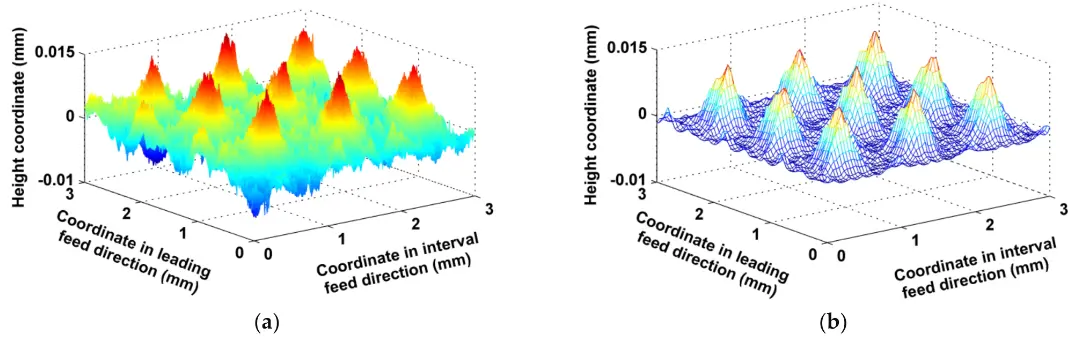
In recent years, non-contact optical measurement technology has been widely used in two-dimensional profile acquisition, providing a new technical approach for surface topography verification. Chen and Wang [37] used a laser displacement sensor to measure side milling surface profiles, effectively avoiding possible surface damage to soft metal materials caused by contact measurement. By comparing the profile lines obtained from simulation and optical measurement, they found that the prediction error of the model considering tool radial runout and axial drift can be controlled within 12%. Buj-Corral et al. [94] combined optical microscopy and image processing technology to realize the extraction of two-dimensional profiles of side milling surfaces, and systematically analyzed the influence of parameters such as feed rate, eccentricity, and helix angle on profile morphology on this basis. Wang et al. [137] assessed the prediction accuracy of surface texture and roughness by comparing the predicted and measured shapes and amplitudes of 2D surface profiles, as shown in Figure 12. In terms of error analysis, researchers usually use statistical indicators such as root mean square error, mean absolute error, and correlation coefficient to quantitatively evaluate the agreement between simulated and measured profiles [138].
For different milling processes, the two-dimensional profile comparison method also differs in its specific implementation. In end milling, Melkote and Thangaraj [111] verified that the front-cut and back-cut model considering tool deflection angle can better reflect the complexity of end surface profiles by comparing simulated and measured results of end profiles. Ryu et al. [47] revealed the distribution characteristics of roughness along the tool axis by comparing two-dimensional profiles at different axial positions on the basis of establishing an end milling surface roughness prediction model. In thin-walled part milling, Zhuo et al. [104] verified the prediction ability of the dynamic model for surface waviness of thin-walled parts by comparing the predicted profiles of the model considering cutting vibration and material removal effect with the measured profiles. It should be pointed out that although the two-dimensional profile comparison method has certain advantages in characterizing features in specific directions, it is difficult to fully reflect the overall spatial distribution characteristics of complex textures. This limitation prompts researchers to gradually move towards a comprehensive comparison method of three-dimensional topography.
4.2. Comparison of 3D Topography
Compared with two-dimensional profiles, three-dimensional topography comparison can restore the spatial geometric characteristics of surfaces more comprehensively, so it has gradually become a key method in evaluating the fidelity of prediction models, especially for model verification of complex machining modes such as five-axis milling [139,140]. This method evaluates the ability of the model to capture the directionality, periodicity, and local defects of surface textures by directly comparing simulated and measured three-dimensional topography maps.
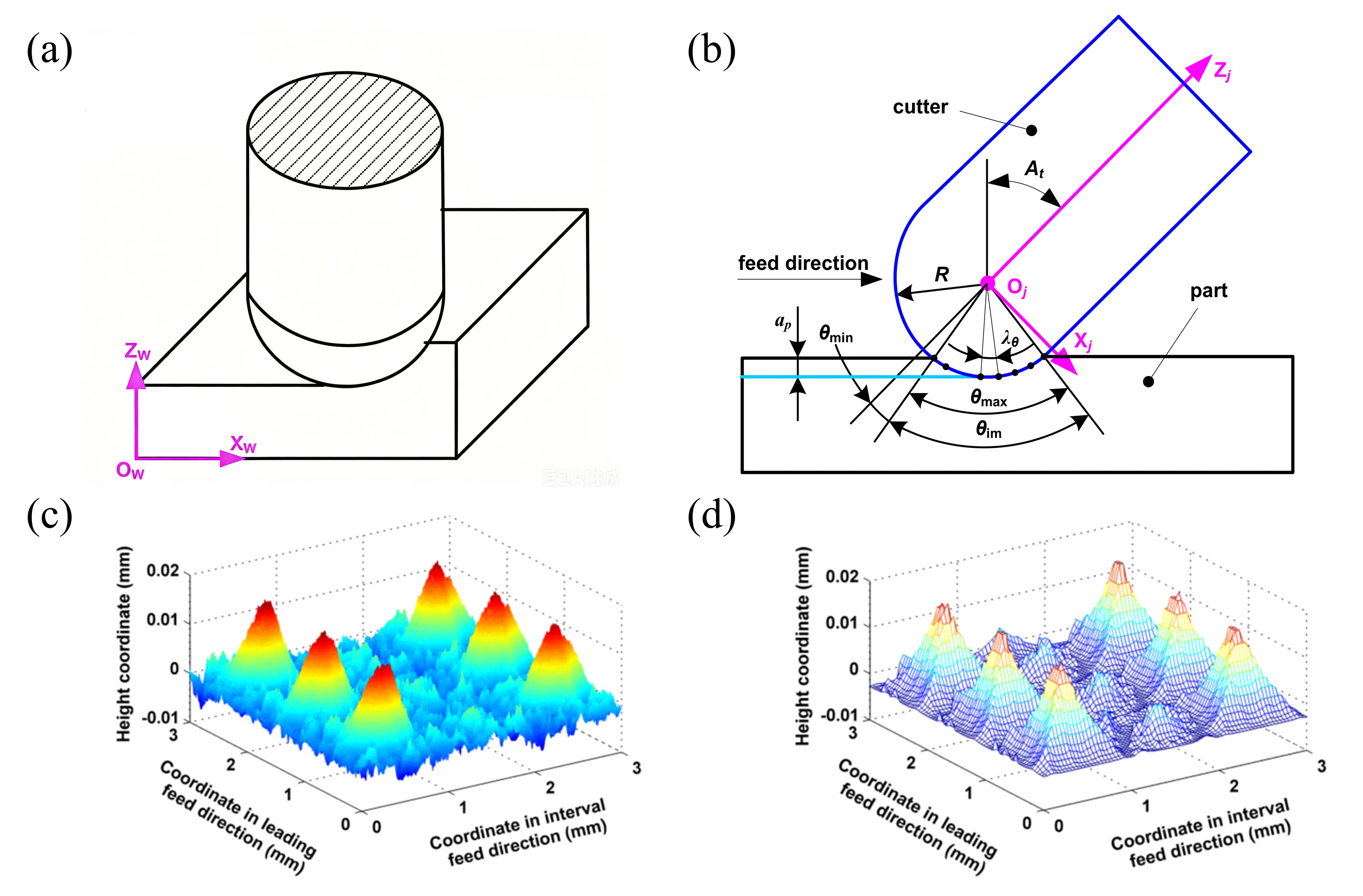
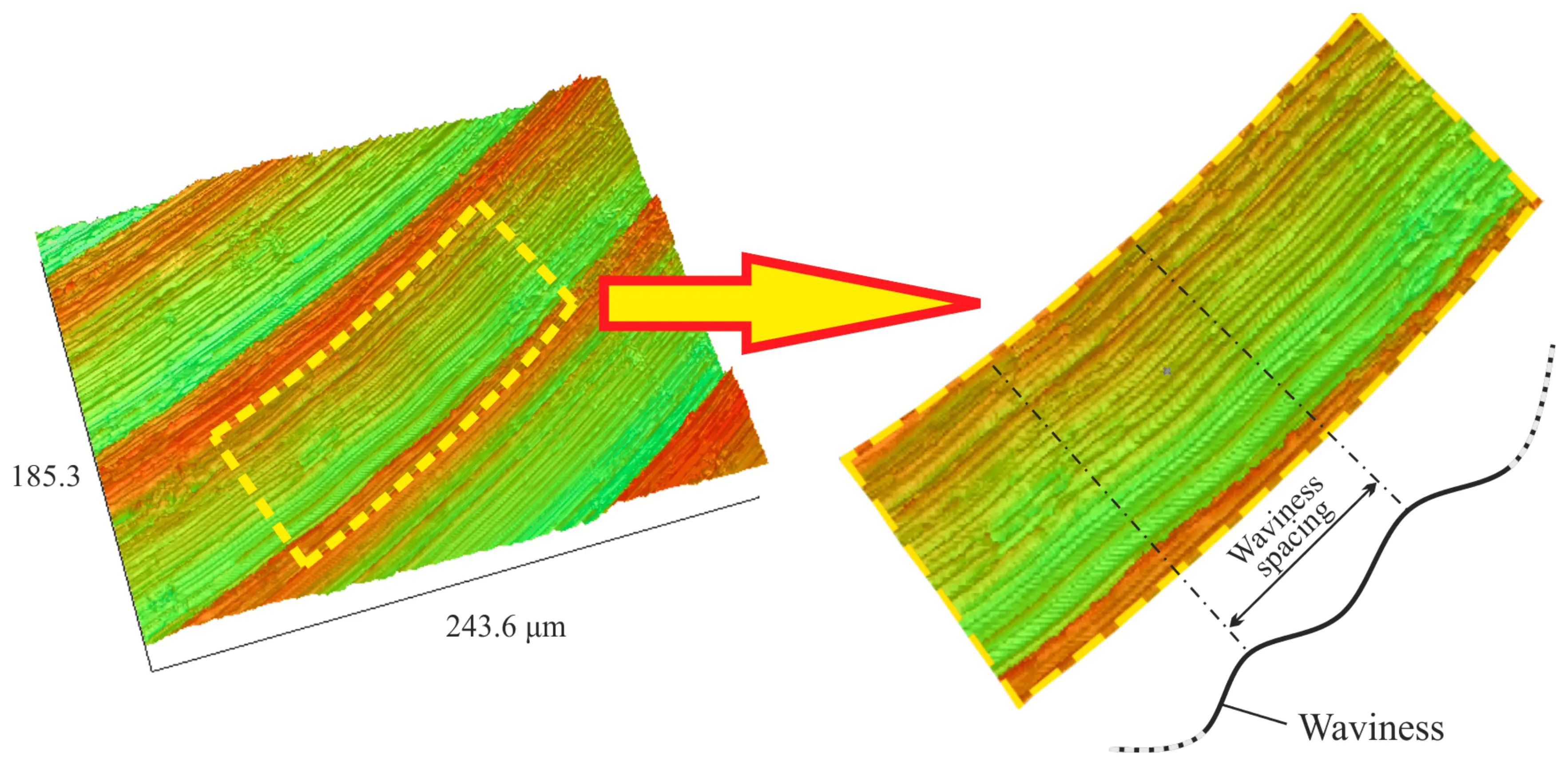
Quinsat et al. [139] used a coherence scanning interferometer to measure the 3D topography of five-axis ball-end milling surfaces, and used 3D parameters defined in the standard [ISO 25178-2]. Liu et al. [140] used an Alicona optical 3D measuring instrument to perform high-resolution measurements of machined surface topography via a non-contact optical method. By comparing parameters such as texture spacing, participating height, and contour lines, they verified the consistency between experimental and predicted results. The above studies provide a technical paradigm for three-dimensional topography comparison, but the systematic analysis of the topography generation mechanism still needs to be further studied. Dong et al. [55] demonstrated through a comparison of 3D topographies that the microsurface topography produced by ball-end milling under a cycloidal cutting pattern closely matches the simulation results, as shown in Figure 13. Furthermore, based on differences in reconstructed and measured surface topography, they conducted a kinematic analysis and found that dynamic factors such as tool radial runout caused these discrepancies. Fu et al. [141] focused on tool orientation, establishing micro-units to extract geometric features of surface texture and developing a general digital model of surface texture topography to enhance the accuracy of verification results.
However, comprehensive comparison of three-dimensional topography faces challenges such as a large calculation amount, long measurement time, and difficult data registration, especially in large-area topography measurement. Image stitching technology is needed to expand the measurement range, which may introduce stitching errors [44,142].
4.3. Comparison of Texture Characteristics and Defect Distribution
To characterize the surface microstructure more precisely, researchers began to focus on the matching degree of texture features and defect distribution to evaluate the prediction ability of models for micro topography. Compared with simple roughness parameters, texture features can better reflect the micro geometric structure, and defect distribution is directly related to the service performance and reliability of parts [107].
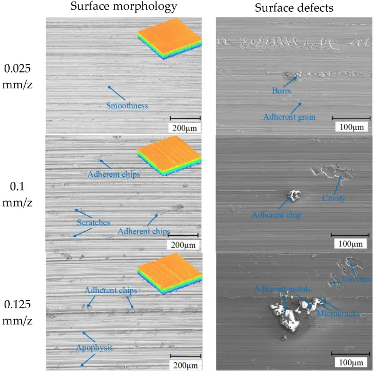
Texture feature analysis refers to the comparison of parameters such as the directionality, periodicity, arrangement patterns, and uniformity of surface textures. Shivanna et al. [143] proposed a method for analyzing milling texture features using a visual system. They conducted subjective analysis by plotting histograms and texture maps, and provided an objective description of the texture using the Grey Level Co-occurrence Matrix (GLCM). Chen et al. [144] introduced wavelet analysis and power spectral density (PSD) methods into the analysis of surface features on machined KDP-Crystal. Wavelet transforms were used to analyze tangential waves on the machined surface, while the 2D PSD method was employed to analyze the morphological anisotropy of the machined surface. In addition, researchers also compare the defect density, location, and morphology of simulated and measured surfaces to evaluate the micro prediction ability of models [116,125]. Lu et al. [145] characterized the surface features of 7050 aluminum alloy under high-speed cutting conditions involving high temperatures, high strain, and high strain rates by evaluating surface topography, defects, and roughness, as shown in Figure 14.
In recent years, the rapid development of deep learning technology has provided new methods for automatic identification of surface defects. Wang et al. [146] developed a strip surface defect detection system based on the improved YOLOv7 model, which can automatically identify various defects on milling surfaces with a detection accuracy of more than 90%. Similarly, convolutional neural networks (CNN) are also used for defect classification [147].
5. Research Limitations and Future Trends
Currently, modeling of milled surface topography has gradually evolved into a technical framework that integrates multiple factors, and some progress has been made in predicting surface topography under conventional machining conditions. However, there remains a lack of systematic solutions and mature methods to address the need for adaptation to complex operating conditions, the characterization of multi-factor coupling, and the balance between prediction accuracy and computational efficiency. Specifically, these challenges manifest in the following three aspects.
- (1)
-
Model adaptability under complex operating conditions remains insufficient. Existing models exhibit significant limitations when addressing scenarios such as milling cutters with variable pitch and helix angles, overlapping multi-pass toolpaths, and micro-specialized machining. The time-varying cutting trajectories caused by tools with variable pitch and helix angles render traditional kinematic models—which are based on the assumption of constant pitch—inapplicable; path overlaps caused by multiple passes result in non-uniform surface topography, making it difficult for forward modeling to effectively track the complex overlapping processes of multiple tooth trajectories; furthermore, in micro-milling and ultrasonic vibration-assisted machining, the applicability of models is further limited due to the insufficient integration of microscale material removal mechanisms and the synergistic effects of external energy fields.
- (2)
-
The characterization of multi-factor coupling mechanisms remains incomplete. Most studies still have not yet established a closed-loop modeling system that encompasses geometric parameters, dynamic responses, material evolution, and process feedback. For example, the nonlinear interactions between tool runout, vibration, and flexural deformation have yet to be systematically quantified. Additionally, the real-time feedback relationship between material dynamic response and process parameters has also not been fully characterized, leading to significant prediction errors in difficult-to-machine materials or unstable cutting regions. Future efforts should advance multi-physics coupling modeling and utilize methods such as machine learning to quantify nonlinear coupling relationships.
- (3)
-
The trade-off between accuracy and efficiency remains unresolved. Complex multi-physics coupling models incur high computational costs, making it difficult to meet the computational efficiency requirements for real-time monitoring and online optimization during machining. Conversely, overly simplified models, while improving computational speed, are prone to significant deviations in scenarios such as unstable cutting zones or the machining of difficult-to-machine materials. Therefore, it is necessary to develop adaptive accuracy control models and establish a hybrid modeling framework that integrates rapid prediction via machine learning with precise corrections from physical models, thereby achieving a dynamic balance between predictive accuracy and computational efficiency.
6. Conclusions
This review systematically summarizes the formation mechanism, modeling methods, and validation approaches of 3D surface topography in milling medically difficult-to-process materials, and analyzes the current research shortcomings and future development trends. The main conclusions are as follows:
- (1)
-
The formation of 3D surface topography in milling medically difficult-to-process materials is essentially the coupling result of tool-workpiece relative motion trajectory reproduction and material dynamic response. Side milling, end milling, and five-axis ball-end milling present distinct topography formation rules due to different motion characteristics and tool-material interaction mechanisms, which are closely related to the unique mechanical and physical properties of medically difficult-to-process materials.
- (2)
-
The 3D topography modeling methods for medically difficult-to-process materials in different milling processes show obvious differentiation under the influence of material properties, cutting conditions, and dynamic factors. Kinematic models are suitable for ideal machining conditions, while dynamic coupling models can effectively improve the prediction accuracy under complex service conditions of medical device machining.
- (3)
-
The validation system of 3D topography prediction models for medically difficult-to-process materials has formed a multi-dimensional evaluation system from 2D profile comparison, 3D topography comparison, to texture feature and defect distribution matching, which provides a reliable quantitative basis for surface quality control of medical implants.
- (4)
-
The current research on 3D topography prediction of medically difficult-to-process materials still has bottlenecks in complex working condition adaptability, multi-factor coupling characterization, and accuracy-efficiency balance. In the future, multi-physics coupling modeling, physics-data driven hybrid modeling, and adaptive precision control will become the core directions to break through the technical barriers of precision machining for medical key components.
- (5)
-
This work provides a unified theoretical and technical reference for 3D topography prediction and precision machining of medically difficult-to-process materials, which is of great significance for improving the machining quality and surface performance of such special materials; nevertheless, the unique thermo-mechanical properties of medically difficult-to-process materials, the multi-factor nonlinear coupling in machining, and the balance between model prediction accuracy and computational efficiency remain the main obstacles to the engineering application of related modeling theories.
Statement of the Use of Generative AI and AI-Assisted Technologies in the Writing Process
During the preparation of this manuscript, the authors used ChatGPT in order to refine the sentence overall. After using this service, the authors reviewed and edited the content as needed and take full responsibility for the content of the published article.
Author Contributions
Conceptualization, Z.G. and Q.A.; Methodology, Z.G.; Software, Z.G.; Validation, Z.G., Z.X., T.Z., D.Y., L.W. and Q.A.; Formal Analysis, Z.G.; Investigation, Z.G. and Z.X.; Resources, T.Z., D.Y., L.W. and Q.A.; Data Curation, Z.G. and Z.X.; Writing—Original Draft Preparation, Z.G.; Writing—Review & Editing, Z.G., Z.X. and Q.A.; Visualization, Z.G.; Supervision, Q.A.; Project Administration, Q.A.; Funding Acquisition, Q.A.
Ethics Statement
Not applicable.
Informed Consent Statement
Not applicable.
Data Availability Statement
Data available on request.
Funding
The work is supported by National Natural Science Foundation of China (52375454).
Declaration of Competing Interest
The authors declare that they have no known competing financial interests or personal relationships that could have appeared to influence the work reported in this paper.
References
-
Xu L-C, Siedlecki CA. Surface texturing and combinatorial approaches to improve biocompatibility of implanted biomaterials. Front. Phys. 2022, 10, 994438. DOI:10.3389/fphy.2022.994438 [Google Scholar]
-
Sousa V, Mardas N, Spratt D, Hassan IA, Walters NJ, Beltrán V, et al. The effect of microcosm biofilm decontamination on surface topography, chemistry, and biocompatibility dynamics of implant titanium surfaces. Int. J. Mol. Sci. 2022, 23, 10033. DOI:10.3390/ijms231710033 [Google Scholar]
-
Farooq MU, Anwar S, Bhatti HA, Kumar MS, Ali MA, Ammarullah MI. Electric discharge machining of Ti6Al4V ELI in biomedical industry: Parametric analysis of surface functionalization and tribological characterization. Materials 2023, 16, 4458. DOI:10.3390/ma16124458 [Google Scholar]
-
Tchinda A, Chézeau L, Pierson G, Kouitat-Njiwa R, Rihn BH, Bravetti P. Biocompatibility of ZrO2 vs. Y-TZP alloys: Influence of their composition and surface topography. Materials 2022, 15, 4655. DOI:10.3390/ma15134655 [Google Scholar]
-
Gao P, Wang M, Liang Z, Gao X, Zan T. Surface morphology generation mechanism of cortical bone longitudinal-torsional ultrasonic vibration assisted micro-milling. J. Manuf. Process. 2025, 145, 301–312. DOI:10.1016/j.jmapro.2025.04.060 [Google Scholar]
-
Li N, Shang Z, Zhao Y, Wang H, Min Q. Optimization of surface roughness for titanium alloy based on multi-strategy fusion snake algorithm. PLoS ONE 2025, 20, e0310365. DOI:10.1371/journal.pone.0310365 [Google Scholar]
-
Hu G, Lu Y, Zhou S, He X, Zhang F, Zhu P, et al. Multi-objective optimization of surface roughness, cutting force, and temperature in ultrasonic-vibration-assisted milling of titanium alloy. Micromachines 2025, 16, 936. DOI:10.3390/mi16080936 [Google Scholar]
-
Kong X, Li C, Li Z, Yang M, Cui X, Liu M, et al. Biological bone and replacement materials in grinding: Force model and processing capability. Intell. Sustain. Manuf. 2025, 2, 10003. DOI:10.70322/ism.2025.10003 [Google Scholar]
-
Davim JP. Machining; Springer: London, UK, 2008. DOI:10.1007/978-1-84800-213-5 [Google Scholar]
-
He C, Zong W. Influencing Factors and Theoretical Models for the Surface Topography in Diamond Turning Process: A Review. Micromachines 2019, 10, 288. DOI:10.3390/mi10050288 [Google Scholar]
-
Gil-Inchaurza M, Beudaert X, Sanchez JA, Munoa J, Dombovari Z. Topography lobes diagram applied to identify waviness features induced by a single-frequency tool vibration in turning. J. Mater. Process. Technol. 2025, 345, 119041. DOI:10.1016/j.jmatprotec.2025.119041 [Google Scholar]
-
Sergey VF, Evgeny EA, Mikhail PK, Artem AE, Artem PL, Enver SM, et al. Milling mechanism of sheet fiberglass plastic by a tungsten carbide tool with diamond and diamond-like wear-resistant coatings. Intell. Sustain. Manuf. 2026, 3, 10002. DOI:10.70322/ism.2026.10002 [Google Scholar]
-
El Baradie MA. Computer aided analysis of a surface roughness model for turning. J. Mater. Process. Technol. 1991, 26, 207–216. DOI:10.1016/0924-0136(91)90134-z [Google Scholar]
-
Shi J, Feng X, Jin X, Cao H. The prediction of 3D surface topography in a high-speed micro-milling process with aerostatic spindle. Tribol. Int. 2024, 193, 109388. DOI:10.1016/j.triboint.2024.109388 [Google Scholar]
-
Chen W, Sun Y, Huo D, Teng X. Modelling of the Influence of Tool Runout on Surface Generation in Micro Milling. Chin. J. Mech. Eng. 2019, 32, 2. DOI:10.1186/s10033-019-0318-x [Google Scholar]
-
Zhu Z, Feng P, Yuan M, Zhou K, Blumberg J, Jiang E, et al. Functionalization and prediction of end milling surface topography based on a perspective decoupling chatter and forced vibration. J. Manuf. Process. 2025, 154, 563–576. DOI:10.1016/j.jmapro.2025.10.007 [Google Scholar]
-
Chen Z, Yue C, Liu X, Liang SY, Wei X, Du Y. Surface Topography Prediction Model in Milling of Thin-Walled Parts Considering Machining Deformation. Materials 2021, 14, 7679. DOI:10.3390/ma14247679 [Google Scholar]
-
Lyu W, Liu Z, Wang B, Cai Y, Liang X, Li L. Modeling and simulation of 3D topographies of slot milled walls and floor surface considering slot bi-sided wall constraints. J. Manuf. Process. 2025, 149, 241–257. DOI:10.1016/j.jmapro.2025.05.052 [Google Scholar]
-
Xu J, Yan F, Wan X, Li Y, Zhu Q. Surface Topography Model of Ultra-High Strength Steel AF1410 Based on Dynamic Characteristics of Milling System. Processes 2023, 11, 641. DOI:10.3390/pr11020641 [Google Scholar]
-
Wei J, Hou X, Sun C. Modeling and simulation of surface topography in five-axis ball end milling. J. Phys. Conf. Ser. 2021, 1820, 012049. DOI:10.1088/1742-6596/1820/1/012049 [Google Scholar]
-
Denkena B, Böß V, Nespor D, Gilge P, Hohenstein S, Seume J. Prediction of the 3D Surface Topography after Ball End Milling and its Influence on Aerodynamics. Procedia CIRP 2015, 31, 221–227. DOI:10.1016/j.procir.2015.03.049 [Google Scholar]
-
Liu C, Gao L, Wang G, Xu W, Jiang X, Yang T. Online reconstruction of surface topography along the entire cutting path in peripheral milling. Int. J. Mech. Sci. 2020, 185, 105885. DOI:10.1016/j.ijmecsci.2020.105885 [Google Scholar]
-
Wei ZC, Wang MJ, Tang WC, Zhu JN, Xia GC. Form error compensation in ball-end milling of sculptured surface with z-level contouring tool path. Int. J. Adv. Manuf. Technol. 2013, 67, 2853–2861. DOI:10.1007/s00170-012-4698-7 [Google Scholar]
-
Huang W-W, Zhang Y, Zhang X-Q, Zhu L-M. Wall thickness error prediction and compensation in end milling of thin-plate parts. Precis. Eng. 2020, 66, 550–563. DOI:10.1016/j.precisioneng.2020.09.003 [Google Scholar]
-
Sun Y, Liu Y, Zheng M, Xu J, Guo Q. A review on theories/methods to obtain surface topography and analysis of corresponding affecting factors in the milling process. Int. J. Adv. Manuf. Technol. 2023, 127, 3097–3131. DOI:10.1007/s00170-023-11723-4 [Google Scholar]
-
Lu X, Hu X, Jia Z, Liu M, Gao S, Qu C, et al. Model for the prediction of 3D surface topography and surface roughness in micro-milling Inconel 718. Int. J. Adv. Manuf. Technol. 2018, 94, 2043–2056. DOI:10.1007/s00170-017-1001-y [Google Scholar]
-
Hu L, Phan H, Srinivasan S, Cooper C, Zhang J, Yuan B, et al. Multimodal data-driven machine learning for the prediction of surface topography in end milling. Prod. Eng. Res. Devel 2024, 18, 507–523. DOI:10.1007/s11740-023-01253-z [Google Scholar]
-
Pawlus P, Reizer R, Królczyk GM, Gupta MK. A State of the Art on Surface Texture Creation Modelling Methods in Machining. Arch. Comput. Methods Eng. 2025, 32, 3141–3167. DOI:10.1007/s11831-025-10229-4 [Google Scholar]
-
Yue C, Gao H, Liu X, Liang SY. Part Functionality Alterations Induced by Changes of Surface Integrity in Metal Milling Process: A Review. Appl. Sci. 2018, 8, 2550. DOI:10.3390/app8122550 [Google Scholar]
-
Zhang SJ, To S, Wang SJ, Zhu ZW. A review of surface roughness generation in ultra-precision machining. Int. J. Mach. Tools Manuf. 2015, 91, 76–95. DOI:10.1016/j.ijmachtools.2015.02.001 [Google Scholar]
-
Manjunath K, Tewary S, Khatri N, Cheng K. Monitoring and Predicting the Surface Generation and Surface Roughness in Ultraprecision Machining: A Critical Review. Machines 2021, 9, 369. DOI:10.3390/machines9120369 [Google Scholar]
-
Liu Z, Guo Q, Sun Y, Wang W, Zhao W, Yang Z, et al. Surface roughness and burr generation in micro-milling: A review. J. Adv. Manuf. Sci. Technol. 2024, 4, 2023017. DOI:10.51393/j.jamst.2023017 [Google Scholar]
-
Wang G, Zhao L, Liu Q, Li X, Sun Y, Chen M. Modelling and experimental investigation of micro-dimpled structures milling with spiral trajectory tool reciprocating motion. Chin. J. Aeronaut. 2025, 38, 102990. DOI:10.1016/j.cja.2024.03.027 [Google Scholar]
-
Guo P, Wang T, Wang J, Zhang S, Wang J, Wang L. Surface topography model for ball-end milling process based on modified sine-cosine algorithm. Surf. Topogr. Metrol. Prop. 2025, 13, 025011. DOI:10.1088/2051-672x/add715 [Google Scholar]
-
Yusof FN, Ismail MF. Unravelling Tool Edge Trajectory Patterns: Implications on Surface Roughness in End Milling Process. J. Mech. Eng. 2023, 12, 81–99. DOI:10.24191/jmeche.v12i1.24639 [Google Scholar]
-
Cai C, An Q, Ming W, Chen M. Modelling of machined surface topography and anisotropic texture direction considering stochastic tool grinding error and wear in peripheral milling. J. Mater. Process. Technol. 2021, 292, 117065. DOI:10.1016/j.jmatprotec.2021.117065 [Google Scholar]
-
Chen H-Q, Wang Q-H. Modelling and simulation of surface topography machined by peripheral milling considering tool radial runout and axial drift. Proc. Inst. Mech. Eng. Part B J. Eng. Manuf. 2019, 233, 2227–2240. DOI:10.1177/0954405419838384 [Google Scholar]
-
Ming W, Cai C, Ma Z, Nie P, Li C, An Q. Milling mechanism and surface roughness prediction model in ultrasonic vibration-assisted side milling of Ti–6Al–4V. Int. J. Adv. Manuf. Technol. 2024, 131, 2279–2293. DOI:10.1007/s00170-023-11109-6 [Google Scholar]
-
Rao VS, Rao PVM. Modelling of tooth trajectory and process geometry in peripheral milling of curved surfaces. Int. J. Mach. Tools Manuf. 2005, 45, 617–630. DOI:10.1016/j.ijmachtools.2004.10.004 [Google Scholar]
-
Hao W, Wan XJ. Prediction Surface Topography in Flank Milling. In International Conference on Intelligent Robotics and Applications; Springer: Berlin/Heidelberg, Germany, 2009; pp. 967–975. DOI:10.1007/978-3-642-10817-4_95 [Google Scholar]
-
Fei J, Lin B, Yan S. Theoretical investigation on the flank milled roughness profile in quasi-homogeneous materials. Int. J. Adv. Manuf. Technol. 2022, 121, 3043–3065. DOI:10.1007/s00170-022-09500-w [Google Scholar]
-
Zhang L, Zheng G, Shi Y, Yang R. Improved tooth trajectory model for prediction of milled surface geometry. Mach. Sci. Technol. 2017, 21, 175–201. DOI:10.1080/10910344.2017.1283959 [Google Scholar]
-
Miao H, Li C, Liu C, Wang C, Zhang X, Sun W. Machined surface prediction and reliability analysis in peripheral milling operations. Int. J. Mech. Sci. 2024, 272, 109193. DOI:10.1016/j.ijmecsci.2024.109193 [Google Scholar]
-
Zhang Y, Wan XJ. Systematic Evaluation of Influence of Process Parameters on Surface Texture in Flank Milling. Adv. Mater. Res. 2013, 823, 165–169. DOI:10.4028/www.scientific.net/amr.823.165 [Google Scholar]
-
Cai C, An Q, Chen M, Ming W. Modelling of end-milled floor surface topography considering system vibration and tool deflection. J. Mater. Process. Technol. 2023, 312, 117864. DOI:10.1016/j.jmatprotec.2023.117864 [Google Scholar]
-
Melkote SN, Sutherland JW, King C. The Effect of Tool Flexibility on Back-Cutting in End Milled Surfaces. J. Manuf. Sci. Eng. 1999, 121, 532–537. DOI:10.1115/1.2832713 [Google Scholar]
-
Ryu SH, Choi DK, Chu CN. Roughness and texture generation on end milled surfaces. Int. J. Mach. Tools Manuf. 2006, 46, 404–412. DOI:10.1016/j.ijmachtools.2005.05.010 [Google Scholar]
-
Baek DK, Ko TJ, Kim HS. A dynamic surface roughness model for face milling. Precis. Eng. 1997, 20, 171–178. DOI:10.1016/s0141-6359(97)00043-3 [Google Scholar]
-
Baek DK, Ko TJ, Kim HS. Optimization of feedrate in a face milling operation using a surface roughness model. Int. J. Mach. Tools Manuf. 2001, 41, 451–462. DOI:10.1016/s0890-6955(00)00039-0 [Google Scholar]
-
Franco P, Estrems M, Faura F. Influence of radial and axial runouts on surface roughness in face milling with round insert cutting tools. Int. J. Mach. Tools Manuf. 2004, 44, 1555–1565. DOI:10.1016/j.ijmachtools.2004.06.007 [Google Scholar]
-
Wang J, Qi X, Ma W, Zhang S. A high efficiency 3D surface topography model for face milling processes. J. Manuf. Process. 2023, 107, 74–87. DOI:10.1016/j.jmapro.2023.10.026 [Google Scholar]
-
Lavernhe S, Quinsat Y, Lartigue C. Model for the prediction of 3D surface topography in 5-axis milling. Int. J. Adv. Manuf. Technol. 2010, 51, 915–924. DOI:10.1007/s00170-010-2686-3 [Google Scholar]
-
Mizugaki Y, Hao M, Kikkawa K, Nakagawa T. Geometric Generating Mechanism of Machined Surface by Ball-nosed End Milling. CIRP Ann. 2001, 50, 69–72. DOI:10.1016/s0007-8506(07)62073-3 [Google Scholar]
-
Liu X, Soshi M, Sahasrabudhe A, Yamazaki K, Mori M. A Geometrical Simulation System of Ball End Finish Milling Process and Its Application for the Prediction of Surface Micro Features. J. Manuf. Sci. Eng. 2006, 128, 74–85. DOI:10.1115/1.2039098 [Google Scholar]
-
Dong Y, Li S, Zhang Q, Li P, Jia Z, Li Y. Modeling and analysis of micro surface topography from ball-end milling in a trochoidal milling mode. Micromachines 2021, 12, 1203. DOI:10.3390/mi12101203 [Google Scholar]
-
Mizugaki Y, Kikkawa K, Terai H, Hao M, Sata T. Theoretical Estimation of Machined Surface Profile Based on Cutting Edge Movement and Tool Orientation in Ball-nosed End Milling. CIRP Ann. 2003, 52, 49–52. DOI:10.1016/s0007-8506(07)60528-9 [Google Scholar]
-
Zhang W-H, Tan G, Wan M, Gao T, Bassir DH. A New Algorithm for the Numerical Simulation of Machined Surface Topography in Multiaxis Ball-End Milling. J. Manuf. Sci. Eng. 2008, 130, 011003. DOI:10.1115/1.2815337 [Google Scholar]
-
Chen J-S, Huang Y-K, Chen M-S. A study of the surface scallop generating mechanism in the ball-end milling process. Int. J. Mach. Tools Manuf. 2005, 45, 1077–1084. DOI:10.1016/j.ijmachtools.2004.11.019 [Google Scholar]
-
Arizmendi M, Fernández J, Lacalle LNLD, Lamikiz A, Gil A, Sánchez JA, et al. Model development for the prediction of surface topography generated by ball-end mills taking into account the tool parallel axis offset. Experimental validation. CIRP Ann. 2008, 57, 101–104. DOI:10.1016/j.cirp.2008.03.045 [Google Scholar]
-
Ehsan Layegh K S, Lazoglu I. 3D surface topography analysis in 5-axis ball-end milling. CIRP Ann. 2017, 66, 133–136. DOI:10.1016/j.cirp.2017.04.021 [Google Scholar]
-
Xu J, Zhang H, Sun Y. Swept surface-based approach to simulating surface topography in ball-end CNC milling. Int. J. Adv. Manuf. Technol. 2018, 98, 107–118. DOI:10.1007/s00170-017-0322-1 [Google Scholar]
-
Biondani FG, Bissacco G. Effect of cutting edge micro geometry on surface generation in ball end milling. CIRP Ann. 2019, 68, 571–574. DOI:10.1016/j.cirp.2019.04.017 [Google Scholar]
-
Wang Z, Wang B, Yuan J. Modeling of surface topography based on cutting vibration in ball-end milling of thin-walled parts. Int. J. Adv. Manuf. Technol. 2019, 101, 1837–1854. DOI:10.1007/s00170-018-3095-2 [Google Scholar]
-
Zheng F, Zhang M, Zhang W, Tan R, Guo X. The fundamental roughness model for face-milling spiral bevel gears considering run-outs. Int. J. Mech. Sci. 2019, 156, 272–282. DOI:10.1016/j.ijmecsci.2019.03.017 [Google Scholar]
-
Wang B, Zhang Q, Wang M, Zheng Y, Kong X. A predictive model of milling surface roughness. Int. J. Adv. Manuf. Technol. 2020, 108, 2755–2762. DOI:10.1007/s00170-020-05599-x [Google Scholar]
-
Liu C, Huang Z, Huang S, He Y, Yang Z, Tuo J. Surface roughness prediction in ball screw whirlwind milling considering elastic-plastic deformation caused by cutting force: Modelling and verification. Measurement 2023, 220, 113365. DOI:10.1016/j.measurement.2023.113365 [Google Scholar]
-
Wu S, Wang D, Zhang J, Nadykto AB. Study on the formation mechanism of cutting dead metal zone for turning AISI4340 with different chamfering tools. Micromachines 2022, 13, 1156. DOI:10.3390/mi13071156 [Google Scholar]
-
Wojciechowski S, Wiackiewicz M, Krolczyk GM. Study on metrological relations between instant tool displacements and surface roughness during precise ball end milling. Measurement 2018, 129, 686–694. DOI:10.1016/j.measurement.2018.07.058 [Google Scholar]
-
Hao Y, Liu Y. Analysis of milling surface roughness prediction for thin-walled parts with curved surface. Int. J. Adv. Manuf. Technol. 2017, 93, 2289–2297. DOI:10.1007/s00170-017-0615-4 [Google Scholar]
-
Chen Z, Yue C, Liang SY, Liu X, Li H, Li X. Iterative from error prediction for side-milling of thin-walled parts. Int. J. Adv. Manuf. Technol. 2020, 107, 4173–4189. DOI:10.1007/s00170-020-05266-1 [Google Scholar]
-
Wan M, Zhang W, Qiu K, Gao T, Yang Y. Numerical Prediction of Static Form Errors in Peripheral Milling of Thin-Walled Workpieces with Irregular Meshes. J. Manuf. Sci. Eng. 2005, 127, 13–22. DOI:10.1115/1.1828055 [Google Scholar]
-
Chen C, Wu C, Zhang T, Liang SY. 3D curved surface milling modeling for the topography simulation and surface roughness prediction. J. Manuf. Process. 2025, 137, 151–165. DOI:10.1016/j.jmapro.2025.02.003 [Google Scholar]
-
Budak E, Tunç LT, Alan S, Özgüven HN. Prediction of workpiece dynamics and its effects on chatter stability in milling. CIRP Ann. 2012, 61, 339–342. DOI:10.1016/j.cirp.2012.03.144 [Google Scholar]
-
Chen D, Zhang X, Xie Y, Zhang X, Ding H. A unified analytical cutting force model for variable helix end mills. Int. J. Adv. Manuf. Technol. 2017, 92, 3167–3185. DOI:10.1007/s00170-017-0357-3 [Google Scholar]
-
Varga J, Ižol P, Vrabeľ M, Kaščák Ľ, Drbúl M, Brindza J. Surface quality evaluation in the milling process using a ball nose end mill. Appl. Sci. 2023, 13, 10328. DOI:10.3390/app131810328 [Google Scholar]
-
List G, Sutter G, Bouthiche A. Cutting temperature prediction in high speed machining by numerical modelling of chip formation and its dependence with crater wear. Int. J. Mach. Tools Manuf. 2012, 54–55, 1–9. DOI:10.1016/j.ijmachtools.2011.11.009 [Google Scholar]
-
Hassanpour H, Rasti A, Khosrowshahi JH, Farshi SS. Effect of ball nose flank wear on surface integrity in high-speed hard milling of AISI 4340 steel using MQL. Heliyon 2024, 10, e37337. DOI:10.1016/j.heliyon.2024.e37337 [Google Scholar]
-
Wu J, Yin N, Lv L, Mai Q. Study on the tool-chip friction coefficient of the bottom edge in high-speed internal cooling spiral milling hole. Int. J. Adv. Manuf. Technol. 2024, 131, 369–380. DOI:10.1007/s00170-024-13109-6 [Google Scholar]
-
Jiang Q, Song J. A Review on Cutting Force and Thermal Modeling, Toolpath Planning, and Vibration Suppression for Advanced Manufacturing. Machines 2026, 14, 60. DOI:10.3390/machines14010060 [Google Scholar]
-
Wang H, Zhang T, Wang S, To S. Characterization of the friction coefficient of aluminum alloy 6061 in ultra-precision machining. Metals 2020, 10, 336. DOI:10.3390/met10030336 [Google Scholar]
-
Löschner P, Niesłony P, Kołodziej S. Parameter Sensitivity Study of the Johnson–Cook Model in FEM Turning of Ti6Al4V Alloy. Materials 2025, 18, 3351. DOI:10.3390/ma18143351 [Google Scholar]
-
Liu H, Ayed Y, Birembaux H, Rossi F, Poulachon G. Impacts of flank wear and cooling strategies on evolutions of built-up edges, diffusion wear and cutting forces in Ti6Al4V machining. Tribol. Int. 2022, 171, 107537. DOI:10.1016/j.triboint.2022.107537 [Google Scholar]
-
Wu C, Yi S, Xu L, Jing J, Ling Y, Lu W. High-temperature oxidation behavior of (TiZrNbMoTa)N high entropy ceramic coating for dry cutting tools. Vacuum 2025, 233, 113897. DOI:10.1016/j.vacuum.2024.113897 [Google Scholar]
-
Khaliq W, Zhang C, Jamil M, Khan AM. Tool wear, surface quality, and residual stresses analysis of micro-machined additive manufactured Ti–6Al–4V under dry and MQL conditions. Tribol. Int. 2020, 151, 106408. DOI:10.1016/j.triboint.2020.106408 [Google Scholar]
-
Zawada-Michałowska M, Anasiewicz K, Korpysa J, Pieśko P. Experimental Investigation of the Influence of Milling Conditions on Residual Stress in the Surface Layer of an Aerospace Aluminum Alloy. Materials 2025, 18, 811. DOI:10.3390/ma18040811 [Google Scholar]
-
Deshpande S, Lagarrigue P, Carla Araujo A. Cutting power model for material identification during helical milling of aerospace stacks. Intell. Sustain. Manuf. 2025, 2, 10026. DOI:10.70322/ism.2025.10026 [Google Scholar]
-
Vogler MP, DeVor RE, Kapoor SG. On the Modeling and Analysis of Machining Performance in Micro-Endmilling, Part I: Surface Generation. J. Manuf. Sci. Eng. 2004, 126, 685–694. DOI:10.1115/1.1813470 [Google Scholar]
-
Liu X, DeVor RE, Kapoor SG. Model-Based Analysis of the Surface Generation in Microendmilling—Part I: Model Development. J. Manuf. Sci. Eng. 2007, 129, 453–460. DOI:10.1115/1.2716705 [Google Scholar]
-
He CL, Zong WJ, Xue CX, Sun T. An accurate 3D surface topography model for single-point diamond turning. Int. J. Mach. Tools Manuf. 2018, 134, 42–68. DOI:10.1016/j.ijmachtools.2018.07.004 [Google Scholar]
-
David C, Sagris D, Stergianni E, Tsiafis C, Tsiafis I. Experimental analysis of the effect of vibration phenomena on workpiece topomorphy due to cutter runout in end-milling process. Machines 2018, 6, 27. DOI:10.3390/machines6030027 [Google Scholar]
-
Arizmendi M, Fernández J, Gil A, Veiga F. Model for the prediction of heterogeneity bands in the topography of surfaces machined by peripheral milling considering tool runout. Int. J. Mach. Tools Manuf. 2010, 50, 51–64. DOI:10.1016/j.ijmachtools.2009.09.007 [Google Scholar]
-
Arizmendi M, Fernández J, Gil A, Veiga F. Effect of tool setting error on the topography of surfaces machined by peripheral milling. Int. J. Mach. Tools Manuf. 2009, 49, 36–52. DOI:10.1016/j.ijmachtools.2008.08.004 [Google Scholar]
-
Arizmendi M, Fernández J, Gil A, Veiga F. Identification of tool parallel axis offset through the analysis of the topography of surfaces machined by peripheral milling. Int. J. Mach. Tools Manuf. 2010, 50, 1097–1114. DOI:10.1016/j.ijmachtools.2010.07.006 [Google Scholar]
-
Buj-Corral I, Vivancos-Calvet J, González-Rojas H. Influence of feed, eccentricity and helix angle on topography obtained in side milling processes. Int. J. Mach. Tools Manuf. 2011, 51, 889–897. DOI:10.1016/j.ijmachtools.2011.08.001 [Google Scholar]
-
Krüger M, Denkena B. Model-based identification of tool runout in end milling and estimation of surface roughness from measured cutting forces. Int. J. Adv. Manuf. Technol. 2013, 65, 1067–1080. DOI:10.1007/s00170-012-4240-y [Google Scholar]
-
Urbikain G, De Lacalle LNL. Modelling of surface roughness in inclined milling operations with circle-segment end mills. Simul. Model. Pract. Theory 2018, 84, 161–176. DOI:10.1016/j.simpat.2018.02.003 [Google Scholar]
-
Urbikain Pelayo G, Olvera-Trejo D, Luo M, López De Lacalle LN, Elías-Zuñiga A. Surface roughness prediction with new barrel-shape mills considering runout: Modelling and validation. Measurement 2021, 173, 108670. DOI:10.1016/j.measurement.2020.108670 [Google Scholar]
-
Arizmendi M, Campa FJ, Fernández J, López De Lacalle LN, Gil A, Bilbao E, et al. Model for surface topography prediction in peripheral milling considering tool vibration. CIRP Ann. 2009, 58, 93–96. DOI:10.1016/j.cirp.2009.03.084 [Google Scholar]
-
Denkena B, Krüger M, Bachrathy D, Stepan G. Model based reconstruction of milled surface topography from measured cutting forces. Int. J. Mach. Tools Manuf. 2012, 54–55, 25–33. DOI:10.1016/j.ijmachtools.2011.12.007 [Google Scholar]
-
Ismail F, Elbestawi MA, Du R, Urbasik K. Generation of Milled Surfaces Including Tool Dynamics and Wear. J. Eng. Ind. 1993, 115, 245–252. DOI:10.1115/1.2901656 [Google Scholar]
-
Elbestawi MA, Ismail F, Yuen KM. Surface topography characterization in finish milling. Int. J. Mach. Tools Manuf. 1994, 34, 245–255. DOI:10.1016/0890-6955(94)90104-x [Google Scholar]
-
Montgomery D, Altintas Y. Mechanism of Cutting Force and Surface Generation in Dynamic Milling. J. Eng. Ind. 1991, 113, 160–168. DOI:10.1115/1.2899673 [Google Scholar]
-
Artetxe E, Olvera D, De Lacalle LNL, Campa FJ, Olvera D, Lamikiz A. Solid subtraction model for the surface topography prediction in flank milling of thin-walled integral blade rotors (IBRs). Int. J. Adv. Manuf. Technol. 2017, 90, 741–752. DOI:10.1007/s00170-016-9435-1 [Google Scholar]
-
Zhuo Y, Han Z, An D, Jin H. Surface topography prediction in peripheral milling of thin-walled parts considering cutting vibration and material removal effect. Int. J. Mech. Sci. 2021, 211, 106797. DOI:10.1016/j.ijmecsci.2021.106797 [Google Scholar]
-
Omar OEEK, El-Wardany T, Ng E, Elbestawi MA. An improved cutting force and surface topography prediction model in end milling. Int. J. Mach. Tools Manuf. 2007, 47, 1263–1275. DOI:10.1016/j.ijmachtools.2006.08.021 [Google Scholar]
-
Gao H, Yue C, Liu X, Nan Y. Simulation of surface topography considering cut-in impact and tool flank wear. Appl. Sci. 2019, 9, 732. DOI:10.3390/app9040732 [Google Scholar]
-
Grossi N, Scippa A, Sallese L, Montevecchi F, Campatelli G. On the generation of chatter marks in peripheral milling: A spectral interpretation. Int. J. Mach. Tools Manuf. 2018, 133, 31–46. DOI:10.1016/j.ijmachtools.2018.05.008 [Google Scholar]
-
Stepan G, Toth M, Bachrathy D, Ganeriwala S. Spectral Properties of Milling and Machined Surface. Mater. Sci. Forum 2016, 836–837, 570–577. DOI:10.4028/www.scientific.net/msf.836-837.570 [Google Scholar]
-
Niu J, Jia J, Sun Y, Guo D. Generation Mechanism and Quality of Milling Surface Profile for Variable Pitch Tools Considering Runout. J. Manuf. Sci. Eng. 2020, 142, 121001. DOI:10.1115/1.4047622 [Google Scholar]
-
Yang D, Liu Z. Surface plastic deformation and surface topography prediction in peripheral milling with variable pitch end mill. Int. J. Mach. Tools Manuf. 2015, 91, 43–53. DOI:10.1016/j.ijmachtools.2014.11.009 [Google Scholar]
-
Melkote SN, Thangaraj AR. An Enhanced End Milling Surface Texture Model Including the Effects of Radial Rake and Primary Relief Angles. J. Eng. Ind. 1994, 116, 166–174. DOI:10.1115/1.2901927 [Google Scholar]
-
Tapoglou N, Antoniadis A. 3-Dimensional kinematics simulation of face milling. Measurement 2012, 45, 1396–1405. DOI:10.1016/j.measurement.2012.03.026 [Google Scholar]
-
Horava C, Reznicek M, Ovsik M. Influence of the number of inserts used for face milling on cutting forces and surface roughness. Materials 2024, 17, 6052. DOI:10.3390/ma17246052 [Google Scholar]
-
Lazkano X, Aristimuño PX, Aizpuru O, Arrazola PJ. Roughness maps to determine the optimum process window parameters in face milling. Int. J. Mech. Sci. 2022, 221, 107191. DOI:10.1016/j.ijmecsci.2022.107191 [Google Scholar]
-
Hadad M, Ramezani M. Modeling and analysis of a novel approach in machining and structuring of flat surfaces using face milling process. Int. J. Mach. Tools Manuf. 2016, 105, 32–44. DOI:10.1016/j.ijmachtools.2016.03.005 [Google Scholar]
-
Arizmendi M, Jiménez A. Modelling and analysis of surface topography generated in face milling operations. Int. J. Mech. Sci. 2019, 163, 105061. DOI:10.1016/j.ijmecsci.2019.105061 [Google Scholar]
-
Liu X, DeVor RE, Kapoor SG. Model-Based Analysis of the Surface Generation in Microendmilling—Part II: Experimental Validation and Analysis. J. Manuf. Sci. Eng. 2007, 129, 461–469. DOI:10.1115/1.2716706 [Google Scholar]
-
Aurich JC, Bohley M, Reichenbach IG, Kirsch B. Surface quality in micro milling: Influences of spindle and cutting parameters. CIRP Ann. 2017, 66, 101–104. DOI:10.1016/j.cirp.2017.04.029 [Google Scholar]
-
Chen W, Xie W, Huo D, Yang K. A novel 3D surface generation model for micro milling based on homogeneous matrix transformation and dynamic regenerative effect. Int. J. Mech. Sci. 2018, 144, 146–157. DOI:10.1016/j.ijmecsci.2018.05.050 [Google Scholar]
-
Börner R, Winkler S, Junge T, Titsch C, Schubert A, Drossel W-G. Generation of functional surfaces by using a simulation tool for surface prediction and micro structuring of cold-working steel with ultrasonic vibration assisted face milling. J. Mater. Process. Technol. 2018, 255, 749–759. DOI:10.1016/j.jmatprotec.2018.01.027 [Google Scholar]
-
Lu H, Zhu L, Yang Z, Lu H, Yan B, Hao Y, et al. Research on the generation mechanism and interference of surface texture in ultrasonic vibration assisted milling. Int. J. Mech. Sci. 2021, 208, 106681. DOI:10.1016/j.ijmecsci.2021.106681 [Google Scholar]
-
Qin S, Zhu L, Wiercigroch M, Ren T, Hao Y, Ning J, et al. Material removal and surface generation in longitudinal-torsional ultrasonic assisted milling. Int. J. Mech. Sci. 2022, 227, 107375. DOI:10.1016/j.ijmecsci.2022.107375 [Google Scholar]
-
Quinsat Y, Sabourin L, Lartigue C. Surface topography in ball end milling process: Description of a 3D surface roughness parameter. J. Mater. Process. Technol. 2008, 195, 135–143. DOI:10.1016/j.jmatprotec.2007.04.129 [Google Scholar]
-
Marin F, Fagali De Souza A, Da Silva Gaspar H, Calleja-Ochoa A, López De Lacalle LN. Topography simulation of free-form surface ball-end milling through partial discretization of linearised toolpaths. Eng. Sci. Technol. Int. J. 2024, 55, 101757. DOI:10.1016/j.jestch.2024.101757 [Google Scholar]
-
Wang X, Jiang Z, Huang X, Sun L, Wang Y. Surface topography prediction and reliability analysis of ball end milling. Measurement 2025, 242, 115770. DOI:10.1016/j.measurement.2024.115770 [Google Scholar]
-
Xiao Y, Ge G, Zeng Z, Feng X, Du Z. An improved Z-MAP method based on the SQP algorithm for fast surface topography simulation of ball-end milling. Int. J. Adv. Manuf. Technol. 2023, 128, 1863–1878. DOI:10.1007/s00170-023-11992-z [Google Scholar]
-
Buj-Corral I, Vivancos-Calvet J, Domínguez-Fernández A. Surface topography in ball-end milling processes as a function of feed per tooth and radial depth of cut. Int. J. Mach. Tools Manuf. 2012, 53, 151–159. DOI:10.1016/j.ijmachtools.2011.10.006 [Google Scholar]
-
Lazoglu I. Sculpture surface machining: A generalized model of ball-end milling force system. Int. J. Mach. Tools Manuf. 2003, 43, 453–462. DOI:10.1016/s0890-6955(02)00302-4 [Google Scholar]
-
Zhang W, Hua B, Zhang L, Si B. Modeling and simulation of Surface Topography in secondary milling with ellipsoid end milling cutter. Int. J. Interact. Des. Manuf. 2024, 18, 5043–5056. DOI:10.1007/s12008-023-01475-6 [Google Scholar]
-
Wang R, Zhao B, Tan D, Wan W. Modelling and optimization of machined surface topography in ball-end milling process. Materials 2024, 17, 1533. DOI:10.3390/ma17071533 [Google Scholar]
-
Shujuan L, Dong Y, Li Y, Li P, Yang Z, Landers RG. Geometrical simulation and analysis of ball-end milling surface topography. Int. J. Adv. Manuf. Technol. 2019, 102, 1885–1900. DOI:10.1007/s00170-018-03217-5 [Google Scholar]
-
Xu J, Xu L, Geng Z, Sun Y, Tang K. 3D surface topography simulation and experiments for ball-end NC milling considering dynamic feedrate. CIRP J. Manuf. Sci. Technol. 2020, 31, 210–223. DOI:10.1016/j.cirpj.2020.05.011 [Google Scholar]
-
Sun Y, Shi Z, Guo Q, Xu J. A novel method to predict surface topography in robotic milling of directional plexiglas considering cutter dynamical displacement. J. Mater. Process. Technol. 2022, 304, 117545. DOI:10.1016/j.jmatprotec.2022.117545 [Google Scholar]
-
Petropoulos GP, Pandazaras CN, Davim JP. Surface texture characterization and evaluation related to machining. In Surface Integrity in Machining; Davim JP, Ed.; Springer: London, UK, 2010; pp. 37–66. DOI:10.1007/978-1-84882-874-2_2 [Google Scholar]
-
Schmitz TL, Couey J, Marsh E, Mauntler N, Hughes D. Runout effects in milling: Surface finish, surface location error, and stability. Int. J. Mach. Tools Manuf. 2007, 47, 841–851. DOI:10.1016/j.ijmachtools.2006.06.014 [Google Scholar]
-
Jiang XJ, Whitehouse DJ. Technological shifts in surface metrology. CIRP Ann. 2012, 61, 815–836. DOI:10.1016/j.cirp.2012.05.009 [Google Scholar]
-
Wang G, Liu X, Chen T, Gao W. An experimental study on milling titanium alloy with a revolving cycloid milling cutter. Appl. Sci. 2020, 10, 1423. DOI:10.3390/app10041423 [Google Scholar]
-
Ding M, Liu X, Yue C, Sun S, Xia W. Research on design and milling performance of unequal gradient helix and variable pitch end mill. J. Manuf. Process. 2023, 106, 347–362. DOI:10.1016/j.jmapro.2023.10.013 [Google Scholar]
-
Quinsat Y, Lavernhe S, Lartigue C. Characterization of 3D surface topography in 5-axis milling. Wear 2011, 271, 590–595. DOI:10.1016/j.wear.2010.05.014 [Google Scholar]
-
Liu J, Niu Y, Zhao Y, Zhang L, Zhao Y. Prediction of Surface Topography in Robotic Ball-End Milling Considering Tool Vibration. Actuators 2024, 13, 72. DOI:10.3390/act13020072 [Google Scholar]
-
Fu G, Zheng Y, Zhu S, Lu C, Wang X, Wang T. Surface texture topography evaluation and classification by considering the tool posture changes in five-axis milling. J. Manuf. Process. 2023, 101, 1343–1361. DOI:10.1016/j.jmapro.2023.07.008 [Google Scholar]
-
Lavernhe S, Quinsat Y, Lartigue C, Brown C. Realistic simulation of surface defects in five-axis milling using the measured geometry of the tool. Int. J. Adv. Manuf. Technol. 2014, 74, 393–401. DOI:10.1007/s00170-014-5689-7 [Google Scholar]
-
Shivanna DM, Kavitha SD, Kiran MB. Texture feature analysis of milled components using vision system. Adv. Mater. Res. 2013, 845, 745–749. DOI:10.4028/www.scientific.net/AMR.845.745 [Google Scholar]
-
Chen D, Zhang S, Liu J, Zha C, Pan R. Morphological analysis of KDP-crystal workpiece surfaces machined by ultra-precision fly cutting. Materials 2020, 13, 432. DOI:10.3390/ma13020432 [Google Scholar]
-
Lu W, Ni C, Wang Y, Zong C, Liu D, Huang X. Surface integrity and machining mechanism of Al 7050 induced by multi-physical field coupling in high-speed machining. Lubricants 2025, 13, 47. DOI:10.3390/lubricants13020047 [Google Scholar]
-
Wang R, Liang F, Mou X, Chen L, Yu X, Peng Z, et al. Development of an Improved YOLOv7-Based Model for Detecting Defects on Strip Steel Surfaces. Coatings 2023, 13, 536. DOI:10.3390/coatings13030536 [Google Scholar]
-
He Y, Song K, Meng Q, Yan Y. An end-to-end steel surface defect detection approach via fusing multiple hierarchical features. IEEE Trans. Instrum. Meas. 2020, 69, 1493–1504. DOI:10.1109/TIM.2019.2915404 [Google Scholar]