1. Introduction
The continued global reliance on fossil fuels has led to significant environmental degradation, highlighting the urgent need for sustainable energy alternatives. Among all energy-intensive sectors, the construction industry remains one of the world’s largest energy consumers. As a result, energy reduction through innovative, context-sensitive design has become a major focus for researchers and a pressing concern for global policymakers [
1]. Energy use within buildings is multifaceted, encompassing lighting, heating, cooling, and ventilation. Thoughtfully designed systems, tailored to local environmental conditions, can significantly reduce energy consumption while enhancing occupant comfort and conserving valuable natural resources. Despite technological advances, many contemporary façade designs overlook critical climatic and environmental factors. This oversight often results in suboptimal thermal performance and an increased reliance on energy-intensive mechanical systems to maintain indoor comfort [
2]. Natural ventilation, a traditional strategy for regulating indoor air quality and removing odors, has long supported passive thermal comfort [
3]. However, with the advent of mechanical ventilation systems in the mid-20th century, the architectural focus shifted toward flexibility in façade design and open-plan layouts. While mechanical systems have enabled greater design freedom, they have also substantially increased energy consumption, with ventilation accounting for up to 39% of energy use in buildings [
4]. This figure rises dramatically in some regions, such as the United States, with ventilation and lighting comprising 79% of total energy consumption. Similarly, in the United Kingdom, these functions account for 72% of building energy use [
5]. Natural ventilation offers a sustainable solution to reduce reliance on fossil fuels and minimize the environmental footprint of buildings [
4]. Its efficacy depends on external environmental factors such as temperature, solar radiation, humidity, and wind. The building envelope, as the interface between the controlled indoor environment and the unpredictable outdoor conditions, plays a pivotal role in optimizing ventilation and energy efficiency [
6]. Controllable façade openings, particularly windows, are critical for facilitating natural airflow. Windows are among the most widely used and adaptable components for enhancing natural ventilation [
7]. Consequently, considerable research has been dedicated to designing windows that maximize airflow efficiency while addressing various environmental challenges [
7]. Modern urban developments are increasingly characterised by dense building configurations, where many residential and office units can access only one façade for natural ventilation and daylight. This architectural limitation stems from the need to maximize land use efficiency, resulting in a proliferation of single-aspect units. Such designs inherently restrict cross-ventilation, leading to suboptimal air exchange rates and a reliance on mechanical systems to meet indoor air quality and thermal comfort requirements [
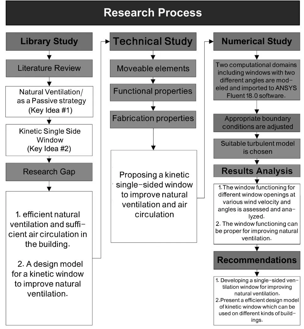
8]. Single-sided ventilation, while an unavoidable reality for these units, often suffers from inadequate airflow dynamics. The lack of distinct inlet and outlet paths for air significantly hampers the ability to create effective natural ventilation. Consequently, a substantial portion of the indoor air remains stagnant, exacerbating issues such as poor air quality, overheating in summer, and insufficient cooling. Given these limitations, the development of solutions tailored specifically to single-sided ventilation is imperative. This study proposes a novel kinetic window system to enhance the role of windows as dynamic components of single-sided façades. By dynamically adapting to varying environmental conditions, the proposed window aims to overcome the inherent disadvantages of single-aspect units while reducing reliance on energy-intensive mechanical systems. To achieve this, the study explores the optimal air change rates required for indoor air quality and assesses the performance of single-sided windows in modern construction. The proposed kinetic window adapts dynamically to varying ventilation needs, supported by computational fluid dynamics (CFD) simulations to evaluate its performance at different angles and wind speeds. The findings in a comprehensive table, offer practical insights for optimizing natural ventilation in real-world applications. summarizes the research process, beginning with the identification of ventilation challenges in modern single-sided designs. It proceeds through the conceptual design of the kinetic window, CFD-based performance evaluation, and result analysis to support practical implementation.
. Research process outlining problem identification, system design, CFD simulation, and performance evaluation.
Research Background
Adequate air exchange is essential for maintaining indoor air quality, with significant implications for energy use and environmental pollution [
1,
9]. Indoor air quality is shaped by a complex interplay of fixed and variable factors, making it challenging to define and regulate. Pollutant concentrations and ventilation effectiveness typically assess indoor air quality. It is adversely impacted by substances such as carbon dioxide, water vapor, volatile organic compounds (VOCs), dust, and fungal spores [
1]. Adequate air exchange and the provision of fresh air are essential for maintaining human comfort, contributing to body cooling through air movement, heat transfer, and the evaporation of skin moisture [
6]. On average, each person requires a minimum fresh air flow rate of 10 L/s to effectively remove odors from indoor air [
10]. Air movement at 0.5 m/s and 1.0 m/s can reduce perceived temperature by approximately 2 °C and 4 °C, respectively. In general, velocities between 0.25 m/s and 1.5 m/s produce a cooling effect ranging from 0 °C to 6 °C [
11].
The functional purpose of air changes differs depending on the building type. For instance, factories rely on ventilation to remove heat, pollutants, and toxic fumes, while closed garages and tunnels require air exchanges to mitigate exhaust gases and potential fire hazards. Hospitals depend on ventilation to reduce infections and airborne bacteria, and residential buildings benefit from air changes to improve thermal comfort and air quality [
12]. outlines recommended air change rates for various spaces, illustrating the potential for natural ventilation to improve environmental conditions while minimizing reliance on energy-intensive mechanical systems.
.
Typical air change rates (ACH) per hour across a range of building types and uses [13].
| Building/Room |
Air Change Rates (ACR) (1/h) |
Building/Room |
Air Change Rates (ACR) (1/h) |
| Attic spaces for cooling |
12–15 |
Department Stores |
6–10 |
| Auditoriums |
8–15 |
Dress Shops |
6–10 |
| Bakeries |
20 |
Factory building, fumes, and moisture |
10–15 |
| Banks |
4–10 |
Fire Stations |
4–10 |
| Beauty Shops |
6–10 |
Precision Manufacturing |
10–50 |
| Churches |
8–15 |
Garages repair |
20–30 |
| Club rooms |
12 |
Homes, night cooling |
10–18 |
| Computer Rooms |
15–20 |
Kitchens |
15–60 |
| Laundries |
10–15 |
Restaurants |
8–12 |
| Libraries, public |
4 |
School Classrooms |
4–12 |
| Malls |
6–10 |
Shopping Centers |
6–10 |
| Medical Centers |
8–12 |
Substation, electric |
5–10 |
| Municipal Buildings |
4–10 |
Town Halls |
4–10 |
| Museums |
12–15 |
Theaters |
8–15 |
| Offices, public |
3 |
Warehouses |
2 |
| Police Stations |
4–10 |
Waiting rooms, public |
4 |
The size and placement of openings primarily determine the effectiveness of air intake and circulation in buildings. Openings smaller than 1/16 of the façade area contribute minimally to airflow, while those smaller than 1/6 of the façade have negligible influence on external air distribution [
14]. Proper building orientation, wind patterns, and façade design play critical roles in ensuring natural ventilation effectiveness [
15]. Additionally, the number and configuration of windows, doors, and façade-integrated components significantly influence ventilation performance [
8]. When appropriately designed and strategically placed, these elements can significantly enhance the overall airflow and ventilation efficiency within a structure.
Ventilation strategies are generally categorized as distributed natural ventilation or stack ventilation. Distributed ventilation relies on openings such as windows and doors to facilitate airflow, while stack ventilation utilizes vertical shafts and pressure differences to direct airflow. Central ventilation shafts, often found in older buildings, are a classic example of stack ventilation [
16]. In such systems, air enters through wall-mounted inlets and exits via elevated outlets, creating a self-contained vertical airflow loop.
Distributed ventilation, on the other hand, can be further divided into two subcategories:
Cross-ventilation method uses openings on opposite façades to allow airflow across the space, achieving high air exchange rates and improved indoor air quality.
Single-sided ventilation occurs when air enters and exits through the same opening, inherently limiting ventilation efficiency due to constrained airflow dynamics (). The absence of distinct pathways for air entry and exit reduces the overall effectiveness of ventilation, making it difficult to achieve adequate air exchange rates. This limitation is especially pronounced in modern windows, where stale air becomes trapped, further reducing ventilation performance.
Building designs must incorporate strategies that establish distinct zones of positive and negative pressure to address these limitations. For instance, ventilation remains negligible when two windows are positioned on walls experiencing similar pressure conditions (positive or negative). Effective ventilation requires controlling wind pressure and airflow direction, which can be achieved by incorporating vertical blades or louvers to redirect and enhance circulation.
These interventions improve a building's ability to create the necessary pressure differentials, facilitating efficient airflow patterns and ensuring proper air circulation. Considering the pivotal role of windows in ventilation, ongoing innovation in window design remains essential. A well-optimised window system boosts airflow efficiency and reduces dependence on mechanical ventilation systems, contributing to energy conservation and improved indoor air quality.
. The schematic comparison of cross ventilation (<b>right</b>) versus single-sided ventilation (<b>left</b>) highlights airflow dynamics and limitations.
Windows are among the most critical components of the building envelope, expected to meet a range of high-performance criteria [
17]. They are pivotal in energy conservation and indoor environmental quality [
18]. The design and material selection of windows are essential in achieving the desired balance of functions, particularly in facilitating natural ventilation. However, achieving these functions often involves addressing conflicting performance requirements. For example, increasing a window's transparency improves natural lighting andaises its thermal conductivity, thereby reducing the overall thermal insulation of the system [
17]. These trade-offs underscore the importance of adopting thoughtful strategies in window design to optimize ventilation without compromising other performance attributes.
Modern windows are often designed to be airtight to improve energy efficiency, but this characteristic limits their ability to support natural ventilation. To address this, controllable openings such as air vents have become essential features to allow fresh air to enter the building envelope [
19]. The development of effective window designs is particularly critical in urban environments, where multi-room layouts and limited façade areas necessitate single-sided ventilation. Single-sided windows, where openings are confined to one building shell, have become the most practical solution for contemporary cities.
Despite their utility, single-sided windows face significant limitations. These include an inability to define effective routes for air exit, insufficient differentiation of positive and negative pressure zones for air movement, and limited penetration depth of airflow—typically only 2.5 times the ceiling height. Such shortcomings drastically reduce the effectiveness of natural ventilation in buildings. These inefficiencies often lead to recommendations against the use of single-sided ventilation in certain scenarios [
11]. Zhao et al. [
20] examined single-sided ventilation in urban residential settings using CFD simulations, confirming its lower effectiveness compared to cross-ventilation due to limited air change rates (ACH) and weaker airflow dynamics. The study highlights how the window-to-wall ratio and building orientation critically impact ventilation performance. Zhao et al. recommend adaptive window designs to mitigate these challenges, particularly in densely populated urban areas with restricted natural airflow pathways. These findings align with earlier research by Allocca [
21] and Erhart et al. [
22], which emphasized the inherent challenges in single-sided ventilation systems, such as fluctuating airflow patterns and dependency on static configurations. Despite advancements in modelling and experimental validations, previous studies lack integration of real-time adaptive technologies capable of dynamically optimizing ventilation performance. Xu et al. [
23]developed a smart façade control framework integrating real-time sensor feedback to optimize ventilation and comfort in naturally ventilated buildings. Similarly, Liu et al. [
24] employed multi-objective AI optimization to fine-tune window geometry in mixed-mode systems, demonstrating the value of real-time data and controllable components ().
.
Components of the Smart Kinetic Window System.
| Component |
Function |
| Aluminium Blade Panels (14,16) |
Adjustable elements that redirect airflow based on wind direction |
| Main and Sub-Levers (40,42) |
Mechanical linkages that transfer rotational motion to the blade system |
| Control Microcontroller (28) |
Processes sensor data and actuates levers accordingly |
| Actuators (38) |
Provide motion to adjust blade angles dynamically |
| Frame and Housing (12) |
Structural enclosure supporting the system and protecting electronics |
While these contributions affirm the growing importance of adaptive building envelopes, they often overlook the architectural and mechanical challenges of implementing effective single-sided ventilation. Specifically, few have addressed the physical design constraints that prevent reliable airflow modulation in such systems.
However, when appropriately designed, single-sided windows can overcome these challenges and emerge as a viable solution for modern buildings. Optimised designs can mitigate these limitations by ensuring better airflow dynamics, reducing reliance on mechanical cooling systems, and achieving energy savings of up to 30% [
25]. Recognizing this potential, the present study proposes an innovative single-sided window design tailored for diverse environmental conditions. By addressing the inherent inefficiencies of conventional single-sided windows, this study aims to provide a practical, energy-efficient solution to enhance natural ventilation in various building types.
This paper presents the first-phase design and validation study of a novel adaptive double-skin window system. The objective is to test whether such a system can achieve dynamic ventilation control through computational simulations before physical prototyping. Building on the identified limitations of traditional single-sided ventilation systems, this study introduces an innovative solution to address these challenges. By incorporating advanced design principles and smart technologies, the proposed kinetic double-skin window aims to enhance natural ventilation efficiency, making it a viable option for modern building applications. Unlike previous designs, which rely on static configurations or intermittent manual operations, this system ensures continuous and efficient ventilation across diverse scenarios, including residential, commercial, and industrial applications. Additionally, the generalization of the design facilitates scalability, reduces manufacturing costs, and broadens its applicability to various building typologies and climates.
2. Proposed Design of the Kinetic Double-Skin Window System
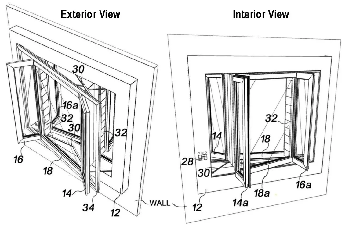
The innovative double-skin window system comprises inner and outer frames ( and , elements 34 and 34a) securely anchored to the frame base (12). The system is designed to dynamically transition between sealed and ventilated states, responding to varying environmental demands. In the closed position, the system functions as a tightly sealed double-skin unit working as a thermal buffer, while in the open position, it enables optimised natural ventilation. The internal frame operates through centrally positioned hinges (, element 36), which allow for smooth opening and closing. The external frame is motorized, enabling precise adjustments to respond to environmental conditions such as wind speed and direction.
The system incorporates carefully positioned openings on the inner and outer frames ( and , elements 14, 14a, 16, and 16a), facilitating effective airflow. The internal frame features inward-facing openings, while the external frame includes outward-facing ones. These openings are coordinated to create synchronized zones for air entry and exit. A flexible material ( and , element 32a) is situated between the two frames, acting as an adaptable channel for directing airflow. This material extends and retracts as needed to accommodate varying environmental conditions and ventilation requirements. When the window is closed, the flexible material retracts into a designated compartment (, element 32), maintaining system compactness and aesthetics.
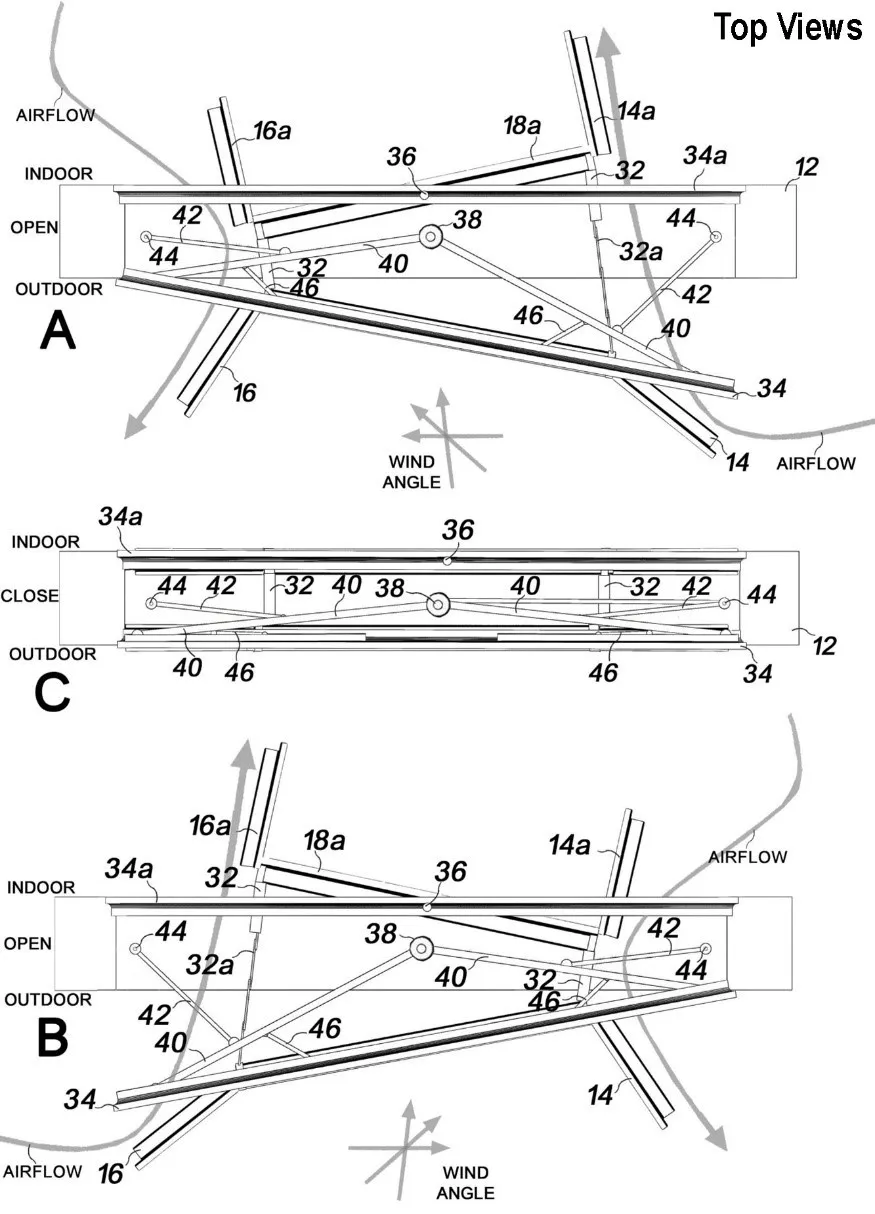
The external blades ( and , elements 14 and 16) are critical for generating positive and negative pressure zones, which drive efficient air exchange. The system uses an external anemometer to monitor wind speed and direction, enabling adaptive blade positioning. For instance:
State A: When wind blows from right to left (0–90°), the external frame opens on the right, directing airflow through the left-side openings (16, 16a) for interior ventilation.
State B: When wind blows from left to right (0–90°), the external frame opens on the left, while the right-side openings (elements 14 and 14a) facilitate ventilation.
Strategically positioned openings on both the inner and outer frames facilitate airflow into and out of the room, while additional structural elements such as element 18 (intermediate panel) and element 18a (inner blade panel) optimize the air distribution. The intermediate panel (element 18) enhances insulation when the window is closed and channels airflow effectively when the window is open. The inner blade panel (element 18a), mounted on the internal frame, works in coordination with external blades (elements 14 and 16) to direct airflow dynamically, ensuring balanced and efficient ventilation inside the room.
In State A, blade 14 on the right side channels airflow into the room with the assistance of the flexible material (element 32a), while blade 14a directs the airflow further into the interior. On the opposite side, blade 16 exhausts indoor air to the exterior, supported by negative pressure, while blade 16a minimizes direct air escape, maintaining balanced airflow dynamics.
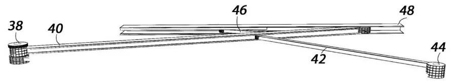
The system's motorized adjustment mechanism (, element 38) enables precise angular modifications of the external frame (element 34). This is achieved via main levers (element 40), which slide along rails (element 48) to ensure stability and alignment during movement. Secondary levers (elements 42 and 46) are connected to axial bearings (element 44), providing additional flexibility and structural resilience. This configuration ensures the system maintains performance and stability under varying environmental conditions, such as high wind loads.
. Visual representation of the proposed double-skin window system installed on a building wall in operational (ventilation) mode.
The window system supports two modes:
Smart Mode: This mode leverages environmental sensors, including an anemometer, thermometer, and hygrometer, to collect real-time data. The integrated AVR microcontroller processes this data and adjusts the blade angles accordingly, ensuring optimal ventilation. This automated mode minimizes human intervention while maximizing efficiency.
Manual Mode: In cases of system malfunctions or power outages, the blades can be operated manually. The motorized components are strategically designed for easy access and maintenance, ensuring system reliability.
The control panel (element 28) serves as the system's intelligent monitoring and management hub. Equipped with sensors such as anemometers, thermometers, and hygrometers, the panel collects real-time environmental data, including wind speed, direction, temperature, and humidity. The control panel processes these inputs using advanced algorithms and communicates with the motorized components to adjust the blade angles and frame positions accordingly. Users can operate the control panel in two modes: smart mode for automated adjustments or manual mode for direct intervention during maintenance or emergencies. In addition to measuring wind velocity, the sensor network can be expanded to include temperature, humidity, and CO
2 sensors, enabling multi-variable environmental sensing. These inputs can feed into a multi-objective control algorithm that adjusts blade angles based on both ventilation demand and thermal comfort priorities.
While the proposed window system operates primarily in automated smart mode, user override functions are available to accommodate individual comfort preferences and maintenance scenarios. The control panel includes manual adjustment options, allowing occupants to intervene if environmental conditions deviate from subjective comfort thresholds. In future development, a user-friendly interface—such as a touch display or mobile app—may be integrated to enable remote monitoring and control. The system’s algorithm can incorporate customizable setpoints (e.g., temperature range: 21–25 °C; humidity: 40–60%; CO
2 threshold: 1000 ppm), ensuring that blade adjustments align with ventilation demand and occupant thermal comfort. This combination of automation and user flexibility enhances system responsiveness and usability across diverse occupancy scenarios.
This advanced structural and mechanical integration enhances the window’s adaptability and reinforces its durability, making it suitable for a wide range of environmental and building conditions.
. Operational states of the smart window system under different wind directions and opening angles, showing adaptive responses. (<b>A</b>) Opened position. (<b>B</b>) Opened position. (<b>C</b>) Closed position.
. Mechanical configurations of the main and sub-levers responsible for adjusting the smart window angle.
3. Methodology
The study of fluid mechanics involves three primary approaches: experimental, analytical, and numerical methods. Experimental methods provide empirical insights but are often costly and time-intensive. Analytical methods, though precise, are limited in their application to simplified systems and are often unsuitable for the complex, nonlinear scenarios typical in engineering problems. Numerical methods have emerged as a powerful alternative due to advancements in computational tools and algorithms, offering a cost-effective and versatile means to solve intricate fluid mechanics problems. These methods have become indispensable for understanding and predicting airflow dynamics in complex geometries, such as those encountered in natural ventilation systems.
3.1. Computational Workflow
The computational methodology employed in this study is a multi-step process designed to evaluate the impact of window geometry on airflow and ventilation efficiency. The workflow includes:
Geometric Modelling: To assess their impact on airflow circulation and indoor ventilation, the study modeled two computational domains, representing windows with 7° and 15° opening angles. The geometries were created using Gambit software and imported into ANSYS Fluent 18.0 for simulation ( and ). In addition to the simulated blade angles (7° and 15°), interpolated estimates were later computed for 9°, 11°, and 13° to extend the design space.
Boundary Conditions and Turbulence Modelling: To replicate real-world scenarios, the simulations employed appropriate boundary conditions, including inlet velocity, outlet pressure, and no-slip wall conditions. The standard k-Epsilon turbulence model was selected for its robust performance in simulating natural ventilation flows.
Numerical Simulation: Airflow and air exchange rates were simulated under steady-state conditions to evaluate the window's performance at different wind angles and speeds.
Validation: Numerical results were validated against experimental data from Reyes et al. [
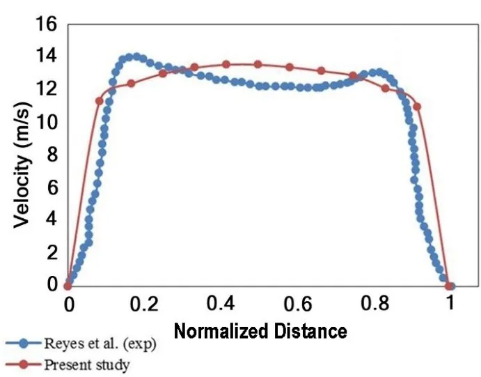
26]. Air velocities were compared at two critical sections: the bottom of the wind tower and the room window. The maximum velocity discrepancy between numerical and experimental data was approximately 2 m/s, confirming the accuracy and reliability of the computational model ().
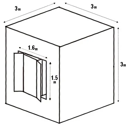
. Modeled room geometry used for CFD simulation, showing the spatial configuration and boundary setup (m).
. Comparison between measured experimental airspeeds and simulated results at the bottom of the window structure, experimental data from Reyes et al. [
26], simulated data (present study).
Numerical simulations were conducted for incompressible, three-dimensional airflow under steady-state conditions. The Finite Volume Method (FVM) was employed for discretizing the Navier-Stokes equations, and the SIMPLE (Semi-Implicit Method for Pressure-Linked Equations) algorithm was used for velocity-pressure coupling to ensure numerical stability [
27].
3.2.1. Navier-Stokes Equation for Incompressible Flow
The continuity equation ensures the conservation of mass for incompressible flow [
27]:
In steady-state incompressible flow, the density (
ρ) is constant
Where:
ρ: Density of the fluid
t: Time
V: Velocity vector
∇: Divergence operator.
The Navier-Stokes equations govern the momentum conservation in the fluid [
28]:
where:
V: Velocity vector
t: Time
ρ: Fluid density
P: Pressure
ν: Kinematic viscosity
g: Gravitational acceleration vector
$$τ_t$$: Turbulent stress tensor.
3.2.2. Standard k-Epsilon Model
This section describes the turbulence model applied in the study and provides a detailed discussion of its governing transport equations. The standard k-Epsilon, a widely utilized turbulence model, is based on transport equations for two key turbulence quantities: the turbulence kinetic energy (
κ) and the turbulence dissipation rate (
ϵ). This model operates under the assumptions of fully turbulent flow and negligible molecular viscosity, making it particularly suitable for modelling high-Reynolds-number flows where turbulence dominates [
27].
The standard k-Epsilon model has been extensively validated and is well-regarded for its robust performance and computational efficiency in modelling natural ventilation scenarios. It is popular due to its ability to produce results that closely match experimental data, particularly for applications involving room airflow and building ventilation [
29,
30].
Governing Transport Equations:
The turbulence kinetic energy (
κ) and dissipation rate (
ϵ) are governed by the following transport equations:
and
where:
ρ: Fluid density
$$u_{i}$$: Velocity component in the iii-th direction
$$G_{k}$$: Generation of turbulence kinetic energy due to mean velocity gradients
$$G_{b}$$: Generation of turbulence kinetic energy due to buoyancy
$$Y_{M}$$: Contribution of compressibility to the overall dissipation rate
$$S_{k}$$ and $$S_{\epsilon}$$: User-defined source terms
$$\mu$$: Molecular viscosity
$$\mu_{t}$$: Turbulent viscosity (modeled as $$\mu_{t} = \rho C_{\mu } \frac{k^{2}}{\epsilon} $$)
$$\sigma_{\epsilon} \, a n d \, \sigma_{k}$$: Turbulent Prandtl numbers for $$\epsilon$$ and $$k$$, respectively
$$C_{1 \epsilon} , C_{2 \epsilon ' } C_{3 \epsilon}$$: Empirical model constants.
3.2.3. Physical Interpretation of Terms
Turbulence Kinetic Energy ($$k$$):
Represents the energy contained in turbulent eddies.
Generated by shear ($$G_{k}$$) and buoyancy effects ($$G_{b}$$).
Dissipated by viscous effects, represented by the term $$\rho \epsilon$$.
Turbulence Dissipation Rate ($$\epsilon$$):
Measures the rate at which turbulence kinetic energy is converted into thermal energy through viscous dissipation.
Additional Terms:
$$Y_{M}$$: Accounts for dilatation effects in compressible turbulence.
$$\sigma_{\epsilon} \, a n d\, \sigma_{k}$$: Control the diffusion rates of $$k$$ and $$\epsilon$$, respectively.
$$S_{k}$$ and $$S_{\epsilon}$$: Provide flexibility to include user-defined effects in the governing equations.
Model Constants
The standard k-Epsilon model employs empirically determined constants that have been widely validated in various flow scenarios:
$$C_{1 \epsilon} $$ = 1.44
$$C_{2 \epsilon }$$ = 1.92
$$C_{3 \epsilon} $$ = Depends on the flow's buoyancy effects
$$\sigma_{k} $$ = 1.0
$$\sigma_{\epsilon} $$ = 1.3.
The standard k-Epsilon model is particularly effective in natural ventilation studies because it balances computational efficiency with accuracy. As demonstrated in this study, its adaptability to varying flow conditions and its compatibility with experimental data make it an ideal choice for simulating airflow through windows and within rooms. By incorporating the effects of turbulence generation, dissipation, and diffusion, the model provides a comprehensive framework for analyzing and optimizing ventilation performance.
3.3. Design Geometry and Mesh Generation
The computational domain was developed using Gambit software, which allowed for precise creation of the room and window geometries. The room geometry is shown in
, and the window was modeled with two distinct opening angles, 7° and 15°, to evaluate their impact on airflow circulation and indoor ventilation (
). These specific angles were selected to represent typical configurations for natural ventilation studies and to assess their effectiveness in promoting air exchange.
The window opening angle directly influences ventilation performance by altering the flow pathways and turbulence intensity. For this reason, the 7° and 15° configurations were chosen to capture the variations in airflow dynamics and their effect on achieving optimal indoor air quality.
3.3.1. Mesh Generation
A structured mesh was generated for the computational domain, ensuring accurate resolution of key flow features. The mesh was refined near critical areas, such as the window openings, walls, and regions of expected high turbulence, to improve accuracy in capturing boundary layer behaviour and flow separation.
Key Mesh Specifications:
-
-
Mesh Type: Structured grid for enhanced numerical stability and accuracy.
-
-
Refinement Zones: High-resolution mesh in the proximity of window edges and airflow interaction zones.
-
-
Element Count: The mesh density was optimised to balance computational efficiency and solution accuracy.
3.3.2. Boundary Conditions
-
-
To replicate real-world conditions, boundary conditions were applied as follows:
-
-
Inlet: Prescribed velocity boundary to simulate external wind.
-
-
Outlet: Pressure-outlet boundary to allow free airflow.
-
-
Walls: No-slip condition to model wall friction effects accurately.
This carefully designed geometry and mesh setup ensured reliable simulation results, providing insights into the influence of window angles on ventilation efficiency.
To ensure the accuracy and reproducibility of the CFD simulations, a mesh independence (grid convergence) study was conducted. Three structured mesh configurations were tested: coarse (~0.8 million cells), medium (~1.6 million), and fine (~3.2 million). Velocity magnitudes were monitored at three key reference points—near the inlet, mid-room (occupant level), and near the outlet—under identical boundary conditions. The maximum deviation between the medium and fine meshes was less than 3.2%, confirming mesh independence at the medium resolution. Therefore, all subsequent simulations were performed using the medium mesh to balance computational efficiency with numerical accuracy.
The computational domain was defined to extend 10 m upstream and 20 m downstream from the window surface, with a lateral extension of 5 m and a vertical height of 8 m. These dimensions exceed standard CFD best practices for external flow simulations to prevent backflow at the outlet and ensure fully developed inflow conditions. A logarithmic wind profile was imposed at the inlet, representative of suburban terrain with a roughness length of 0.5 m. The top boundary was set as a symmetry condition, and a pressure outlet with zero gauge pressure was used at the downstream end. All wall boundaries were modelled using no-slip conditions.
The simulations were conducted under isothermal conditions at 298 K to isolate wind-driven ventilation effects. Radiation and ambient temperature variation were not explicitly included in this model; this simplification is acknowledged as a limitation, particularly under low wind speeds where buoyancy effects may dominate. Future work will incorporate thermal gradients and radiative exchange to simulate hybrid ventilation scenarios in naturally ventilated buildings.
No wall heat transfer coefficients were applied. Instead, standard wall functions were employed to resolve near-wall flow, with the dimensionless wall distance (Y⁺) ranging from 30 to 140—appropriate for the high-Reynolds number regime of the standard k-ε turbulence model.
The standard k-ε turbulence model was employed in this study due to its robustness, computational efficiency, and widespread validation in ventilation and airflow applications. This model is particularly effective for simulating fully developed turbulent flows in domains where wall effects and recirculations are present, such as building interiors and façade-adjacent regions.
While it is acknowledged that alternative models, such as RNG k-ε and SST k-ω, offer enhanced accuracy in predicting flow separation, streamline curvature, and near-wall phenomena, these models come with higher computational costs and convergence sensitivity. The RNG k-ε model, for example, incorporates additional terms for strain rate and better handles swirling flows, whereas the SST k-ω model is more adept at resolving boundary layer transitions and adverse pressure gradients.
However, several comparative studies have shown that for high-Reynolds number flows where gross flow patterns and bulk air exchange rates are the primary metrics—as is the case in this study—the standard k-ε model performs satisfactorily, especially when combined with appropriate wall functions. This choice also aligns with the validation dataset employed from Reyes et al. (2015) [
26], which was modelled and compared using the same turbulence formulation.
Given the objective of this study—to evaluate the macroscopic ventilation performance of an adaptive façade system under various wind conditions rather than resolve microscale turbulence or heat transfer interactions—the standard k-ε model offers an optimal balance of accuracy, numerical stability, and computational efficiency. Nonetheless, future work may include model comparisons with RNG k-ε and SST k-ω formulations to assess turbulence sensitivity and near-wall resolution improvements further.
To ensure the numerical model's accuracy and reliability, the simulated air velocity resultsere validated against experimental data reported by Reyes et al. [
26]. This validation process was critical to establishing the capability of the computational model in predicting airflow behaviour within the room.
The validation focused on two specific sections: the bottom of the wind tower and the room window. presents a comparative analysis of air velocity profiles obtained from the numerical simulations and experimental measurements.
3.4. Quantitative Validation Metric
To further quantify the agreement between simulated and experimental results, the root-mean-square deviation (RMSD) [
31] was calculated. The RMSD measures the average percentage deviation between simulated velocities (Sim
n) and experimental velocities (Exp
n), normalized by the simulated values. The equation takes the squared difference between the simulated and experimental data, scales it by 100 to express it as a percentage, sums these squared deviations over all data points (N), and then divides by the number of data points before taking the square root. RMSD provides a single value that quantifies the overall accuracy of the simulation relative to the experimental data, with lower values indicating better agreement. The RMSD is defined as follows:
The RMSD for the air velocity comparison was determined to be low, indicating a strong correlation between the numerical model predictions and experimental observations. The visual comparison in further supports the validity of the model, showing consistent trends and minimal deviations in air velocity profiles. This visual comparison offers valuable insights into the concordance between our modelling predictions and the empirically observed outcomes. The RMSD was calculated to be 0.33%. The relatively low RMSD value signifies a good degree of agreement between our model's predictions and the experimental data. This agreement demonstrates the effectiveness of the developed model in capturing the behaviour of the suggested window in natural ventilation.
While this study relies on validated computational fluid dynamics (CFD) simulations, no physical prototype was constructed at this stage. Validation was conducted by comparing simulated air velocities with third-party experimental data from Reyes et al. [
26], using 12 measurement points under equivalent wind conditions. The Root Mean Square Deviation (RMSD) between simulated and experimental values was calculated as 0.33%, representing the normalized deviation relative to the mean experimental velocity. This exceptionally low RMSD confirms the model’s high accuracy and reliability in capturing realistic air circulation behavior. Future research will focus on building a full-scale prototype and conducting wind tunnel tests further to verify system performance under controlled and real-world conditions.
While CFD simulations were performed for two mechanical limits of blade deflection (7° and 15°), we recognized the value of predicting performance at intermediate blade angles. To this end, we estimated air circulation and ACH values for additional angles of 9°, 11°, and 13° using linear interpolation between the simulation outputs for 7° and 15°, under fixed wind conditions of 3 m/s wind speed and 45° wind direction. This approach was supported by the quasi-linear trend observed between blade angle and average air velocity and ACH in the CFD results. The method assumes steady-state boundary conditions and uniform geometry. These interpolated values are not substitutes for full CFD but offer design-level estimates to guide performance comparisons across the operational range of the window system. All interpolated results are clearly identified in the relevant tables and figures.
4. Results
This section presents the findings from the numerical simulations conducted to evaluate the performance of the proposed smart window under varying wind velocities and directions. The analysis investigates the influence of window opening angles on airflow dynamics and indoor ventilation efficiency. Key parameters studied include wind velocity, wind direction, and the opening angle of the window, which are critical in determining the air circulation behaviour.
Numerical simulations were performed for four wind velocities (1, 2, 3, and 4 m/s) and three wind directions (0°, 45°, and 90°) to evaluate the interaction between airflow and the smart window. Two window configurations with opening angles of 15° and 7° were analysed to assess the impact of window positioning on air circulation. These simulations aimed to quantify the effect of wind velocity, wind direction, and window angle on natural ventilation performance.
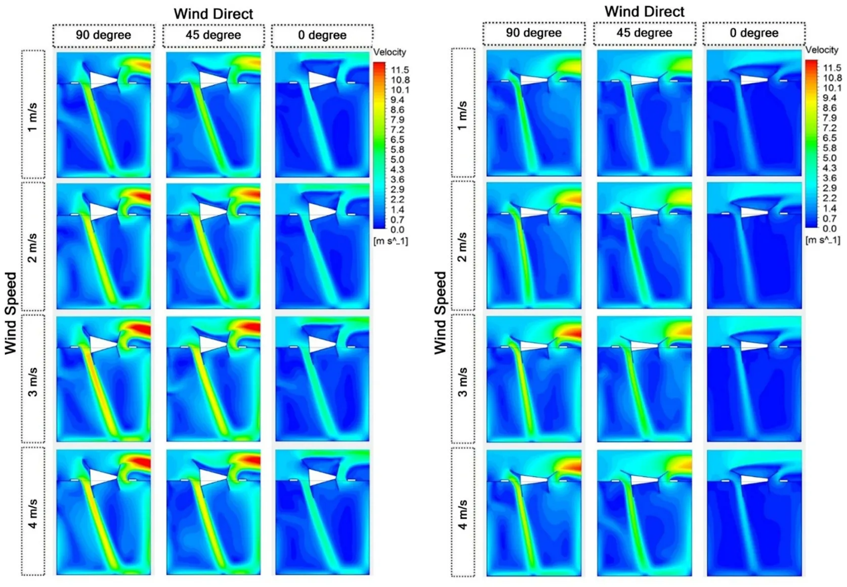
The performance of the 15° window configuration was evaluated under varying wind velocities (1, 2, 3, and 4 m/s) and directions (0°, 45°, and 90°), as presented in . The airflow velocity contours indicate that the window's orientation significantly influences indoor ventilation by directing airflow into the room and generating circulation patterns that enhance air mixing.
As the wind direction transitions from 0° to 90°, the volume flow rate entering the room increases. At 0°, the wind aligns directly with the window opening, resulting in a linear airflow pattern that primarily follows the wind direction. This configuration exhibits limited internal air mixing, as the airflow directly enters and exits the room without significant interaction with indoor air.
In contrast, at 45°, the airflow creates more dynamic circulation patterns within the room, improving air distribution and enhancing ventilation. The 90° wind direction, where the window is perpendicular to the incoming wind, produces the maximum airflow rate. This is attributed to the large pressure differential between the windward and leeward sides of the window, driving efficient air exchange.
Wind velocity further amplifies the ventilation efficiency. As the velocity increases from 1 m/s to 4 m/s, the air exchange rate rises proportionally due to enhanced pressure gradients. The airflow penetrates deeper into the room, reducing stagnant zones and improving overall ventilation. The results indicate that the 15° configuration effectively balances airflow stability and circulation, making it suitable for moderate wind conditions.
The 7° window configuration was also analysed under the same wind conditions (1, 2, 3, and 4 m/s, and 0°, 45°, and 90°), as shown in . The narrower window angle exhibited superior natural ventilation performance by significantly increasing inlet airflow velocities compared to the 15° configuration.
The velocity contours reveal that the reduced angle accelerates the incoming air, enabling greater air penetration into the room. This results in enhanced ventilation efficiency, particularly at higher wind velocities. The airflow dynamics indicate that the 7° window performs exceptionally well at 90°, where the perpendicular wind direction maximizes the pressure differential and generates the highest air exchange rate. At 45°, the window maintains a strong circulation pattern, effectively mixing the fresh air with indoor air. At 0°, the narrower angle creates a more focused and intense airflow, further improving ventilation performance.
Wind velocity continues to play a critical role in the performance of the 7° window. Higher wind speeds result in greater airflow rates, which enhance the overall ventilation efficiency. This configuration minimises stagnant air zones and enhances air mixing, making it suitable for environments with high ventilation demands. However, the increased velocity and intensity of airflow may lead to slightly less stable indoor air circulation compared to the 15° configuration.
. Simulated air circulation contours for the smart window at 15° (<b>left</b>) and 7° (<b>right</b>) opening angles under varying wind directions (0°, 45°, and 90°) and velocities (1–4 m/s), illustrating air circulation and penetration.
The comparative analysis of the 15° and 7° window configurations reveals distinct advantages and performance characteristics under varying wind conditions. Both configurations effectively promote natural ventilation; however, the choice of angle significantly influences airflow behaviour, ventilation efficiency, and stability. To further characterize the performance potential of the kinetic window system, we estimated air change rates at three intermediate blade angles (9°, 11°, and 13°) using linear interpolation between the validated CFD results for 7° and 15°. These estimates were based on the nearly linear airflow behavior observed across angles and were calculated under a fixed wind condition of 3 m/s and 45° wind direction. The resulting values (see ) provide additional design insight into performance tuning for various space types.
The 15° window configuration demonstrates a balanced approach to ventilation. Its moderate angle directs airflow into the room while maintaining stability and consistent circulation patterns. This configuration is particularly effective at 45° and 90° wind directions, where air circulation and exchange are optimised. At higher wind velocities, the 15° configuration ensures a steady airflow, making it suitable for environments requiring consistent indoor air quality without excessive turbulence.
On the other hand, the 7° window configuration excels in achieving higher air velocities and more intensive ventilation. The narrower angle focuses the incoming airflow, significantly increasing air exchange rates and improving indoor air distribution. This configuration performs exceptionally well under high wind velocities and at 90° wind direction, where it achieves the highest ventilation efficiency. However, the focused nature of the airflow may result in less stability compared to the 15° configuration, which could impact applications requiring steady indoor conditions.
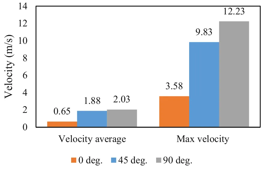
As illustrated in , wind direction strongly influences the average and maximum air velocities within the room. At a constant wind velocity of 3 m/s, increasing the wind direction angle from 0° to 90° results in a proportional increase in average air velocity. Specifically, the average velocity rises from 0.65 m/s at 0° to 1.88 m/s at 45°, and to 2.03 m/s at 90°. Similarly, the maximum air velocity increases from 3.58 m/s at 0° to 9.83 m/s at 45°, and reaches a peak of 12.23 m/s at 90°. These findings emphasize the effectiveness of larger wind angles in promoting natural ventilation by creating more favorable pressure differentials that drive airflow into and through the room.
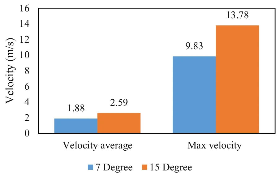
The comparison of two window configurations at a wind velocity of 3 m/s is presented in , highlighting the impact of window opening angles on airflow dynamics. The 15° window configuration achieves significantly higher average and maximum air velocities compared to the 7° configuration. Specifically, the 15° window increases the average velocity by approximately 40%, from 1.88 m/s to 2.59 m/s, and the maximum velocity from 9.83 m/s to 13.78 m/s. This enhancement in airflow velocities demonstrates the superior performance of the 15° configuration in achieving desirable air exchange rates.
. Average and maximum indoor air velocity at different wind directions for the 7° window configuration at 3 m/s.
. Comparative air velocity (m/s) outcomes for the 15° and 7° window configurations under 45° wind direction.
The performance of the proposed 7° and 15° window configurations was analysed under varying wind velocities and directions to determine their suitability for different building types and ventilation needs. Calculating the ACH for each scenario compared the results against standard ventilation requirements outlined in . This comparison identifies configurations best suited for specific applications, ranging from residential spaces requiring low ACH to industrial environments with high ventilation demands. The following table comprehensively analyses the ACH results, highlighting their applicability to different building types and offering insights into optimal configurations based on wind conditions.
The CFD simulations reveal distinct airflow behaviours associated with varying wind directions and window configurations. As illustrated in , at 15° blade openings, airflow enters the room more forcefully and penetrates deeper into the interior zone, producing stronger velocity gradients along the central axis. This configuration promotes high-volume displacement ventilation and is particularly suitable for scenarios requiring high ACH values, such as workshops or production spaces.
In contrast, the 7° blade opening moderates airflow velocities and produces more stable and laminar internal flow patterns, minimising turbulent zones near occupied levels. This behaviour supports occupant comfort by avoiding draught effects and is more suitable for office or residential applications.
and show that wind direction significantly influences airflow symmetry and effectiveness. Under 45° oblique wind incidence, intake and exhaust streams are balanced due to the strategic blade positioning on opposing sides. Under direct (0°) or perpendicular (90°) wind, airflow tends to concentrate on one side, leading to asymmetric distribution unless compensated by flexible elements (e.g., inner ducts).
Analysis of pressure fields shows that the external blade configuration effectively creates high and low pressure zones at intake and exhaust openings, driving passive airflow without auxiliary fans. These pressure differentials are critical for sustaining flow even under moderate wind speeds.
The flexible airflow duct (element 32a) dynamically adjusts during operation to preserve cross-room flow continuity, reducing flow stagnation near the rear zones of the space. In angled wind (45°) scenarios, the duct's adaptability maintains ventilation efficiency even with uneven pressure distribution.
The ACH values obtained ( and ) confirm that the 15° configuration consistently outperforms the 7° in raw air exchange but at the cost of increased flow velocity, which may not always be desirable for occupant-centric environments. This trade-off highlights the importance of mode selection and adaptive blade adjustment.
Overall, the CFD outcomes verify that the proposed kinetic window system responds adaptively to environmental inputs, optimising airflow direction and volume based on external conditions. These findings validate the mechanical logic and aerodynamic principles embedded in the design and form the foundation for future real-world prototyping and deployment.
.
Comparative analysis of ACH values for 7° and 15° window configurations under various wind conditions and associated building applications.
| Window Configuration |
ACH Range |
Suitable Spaces |
Comments |
| 7° Window Angle–45° Wind Direction |
48.00–237.33 |
Garages, manufacturing spaces, not ideal for low-activity spaces |
Simulated |
| 9° Window Angle–45° Wind Direction |
64.00–284.25 |
Classrooms, clinics, circulation spaces |
Interpolated |
| 11° Window Angle–45° Wind Direction |
80.00–331.16 |
Offices, retail, restaurants |
Interpolated |
| 13° Window Angle–45° Wind Direction |
96.00–378.08 |
Libraries, laundries, workshops |
Interpolated |
| 15° Window Angle–45° Wind Direction |
112.00–460.00 |
Industrial environments, large spaces |
Simulated |
While velocity magnitudes provide spatial detail of airflow dynamics, the Air Change Rate per Hour (ACH) is the most relevant metric for quantifying ventilation performance in building spaces. ACH reflects the volumetric exchange of air relative to the indoor volume and is critical for assessing compliance with ventilation standards and indoor air quality requirements.
In this study, ACH values were calculated by integrating inlet/outlet volumetric flow rates over the room volume under steady-state wind conditions. It is important to note that the ACH values presented reflect peak conditions based on constant external wind forces. In real-world applications, these values would vary temporally with fluctuating wind speed and direction, and typically average lower than peak estimates.
High ACH values observed in some configurations (e.g., >100/h) result from forced wind conditions and an unobstructed internal geometry, which serve as a benchmark for evaluating system potential. These values should not be interpreted as continuous operational ventilation rates but rather as design-case indicators for comparative performance under idealised conditions. Future work will incorporate time-averaged ACH under variable environmental inputs and internal occupancy to reflect operational norms.
The results underscore the significant potential of the smart adaptive system embedded in the proposed window design to adjust its performance based on varying ventilation demands dynamically. The ACH values presented in this study represent theoretical peak ventilation rates under idealized CFD conditions, such as consistent wind direction, speed, and unobstructed room geometry. These high values reflect the system’s maximum performance potential, useful for comparative analysis and design optimization. However, actual operational ACH values in real-world conditions will vary significantly due to fluctuating environmental variables, internal obstructions, and dynamic occupant behavior. As such, these results should be interpreted as upper-limit estimates rather than continuous or average real-life performance metrics.
By utilizing real-time environmental data, such as wind speed and direction, the adaptive system modulates the window's blade angles to optimize airflow and indoor air quality. While this study focused on wind-driven natural ventilation, the proposed intelligent window system is conceptually extendable to operate based on combined environmental criteria, including temperature, humidity, and indoor air quality indicators such as CO
2 concentration. For example, if indoor temperature exceeds a comfort threshold and CO
2 levels are elevated, the system could prioritize blade opening even under weak wind conditions. This multi-objective adaptive logic enhances thermal comfort and air quality, particularly in mixed-mode or transitional climate zones. Such flexibility positions the system as suitable for diverse applications, from low-demand residential settings to high-activity spaces like schools, industrial facilities, or healthcare environments.
The adaptive system ensures that the window responds dynamically to changing conditions. During high wind speeds, the system reduces the window angle to prevent excessive airflow and over-ventilation, which could cause discomfort or energy inefficiency. Conversely, under low wind conditions, the system increases the angle to maximize air entry and maintain adequate air exchange rates. This intelligent adaptability not only enhances the window's performance across different environmental conditions but also reduces the reliance on static or mechanical ventilation systems, contributing to energy efficiency and occupant comfort.
At low wind speeds (e.g., 1–2 m/s), larger angles such as 15° are more effective for achieving adequate air change rates, particularly in high-demand scenarios such as kitchens or industrial areas. In contrast, smaller angles such as 7° may result in insufficient airflow in such conditions unless paired with high wind directions. At high wind speeds (e.g., 3–4 m/s), smaller angles prevent over-ventilation, making them suitable for residential and office environments that require controlled air exchange rates, while larger angles can achieve higher air exchange rates, ideal for industrial or high-activity areas. The inclusion of interpolated performance values for intermediate blade angles (9°, 11°, and 13°) enables a more nuanced understanding of the system’s adaptability. These angles, positioned within the system’s mechanical limits, correspond to ventilation needs for a wide range of space types—from moderate-occupancy classrooms to high-intensity areas like kitchens. By providing this performance spectrum, the study supports more flexible and application-specific control logic, which could be integrated into future prototypes.
Moreover, the generalization in the window's design enhances its scalability and adaptability, reducing the need for multiple specialized designs and significantly lowering the costs of commercialization. This standardized yet flexible approach not only simplifies the manufacturing process but also broadens the market applicability of the product. By addressing a wide range of building typologies and environmental conditions, the smart adaptive window system represents a cost-effective and energy-efficient solution for modern ventilation challenges. However, further research and testing are necessary to assess its long-term performance, maintenance requirements, and integration with other building systems, ensuring its practicality and reliability in real-world applications.
The proposed smart kinetic window system was designed with real-world feasibility in mind. It utilises standard construction materials such as lightweight aluminium blades and thermally stable polymer ducting, both of which are commercially available and cost-effective. The modular design allows integration into new and existing buildings without major structural modifications. Environmental sensors are embedded in a weatherproof casing and connected to a central microcontroller, enabling automated operation with minimal user intervention. A manual override ensures system functionality during power outages or maintenance. Maintenance is simplified through removable blade panels and easily accessible actuator housings. These features collectively support the system’s scalability, manufacturability, and long-term reliability in diverse building environments.
This study is based solely on steady-state CFD simulations. It does not incorporate transient airflow behaviours, thermal gradients, or indoor pollutant dispersion, which may significantly influence ventilation dynamics in real settings. Additionally, simulations assume idealised conditions—uniform wall boundaries, absence of interior obstructions, and constant wind speeds—that may not fully represent actual building environments. Although model validation was achieved through comparison with published experimental data, no physical prototype was fabricated or tested. Future work will focus on the design, construction, and testing of a working prototype under real environmental conditions to evaluate long-term performance, sensor integration, user interaction, and system resilience under operational variability. This study represents the first phase of a multi-stage research effort to develop an intelligent dynamic double-skin window system for enhanced natural ventilation. The focus at this stage was to validate the aerodynamic performance of the proposed design using computational fluid dynamics (CFD), and to evaluate how blade angle modulation impacts airflow and ACH under variable boundary conditions.
Although the CFD model was rigorously validated against third-party experimental data from Reyes et al. [
26] and achieved a root mean square deviation (RMSD) of 0.33%, we acknowledge the absence of physical prototyping as a limitation. All simulation results were also shown to be mesh-independent and numerically stable, increasing the reliability of our findings.
Future work will involve fabrication and experimental testing of a physical prototype, including wind tunnel validation, energy performance measurements, and user interface testing. These efforts will enable real-world verification of the proposed system’s adaptive behavior and help assess its integration potential in both retrofitted and new construction projects.
Although this study focused on airflow performance through CFD simulation, the system’s potential for energy savings and economic feasibility warrants initial discussion. Natural ventilation strategies—such as those proposed here — have been shown in prior studies to reduce mechanical cooling loads by 20–30% in temperate climates when used during transitional seasons. Given the substantial increase in ACH demonstrated by the adaptive window system (e.g., 2×–4× improvement between 7° and 15°), it is reasonable to expect a reduction in HVAC energy consumption, especially in retrofit applications where cross-ventilation is not feasible.
The proposed window system is designed with modularity and retrofitting in mind. The external blade module can be fabricated from standard aluminum profiles, with actuation by low-voltage servo motors and environmental sensors (e.g., anemometer, thermometer, hygrometer) controlled via a simple microcontroller (e.g., Arduino). Based on current (2025) component prices, a preliminary cost estimate suggests material costs of less than $80–100 USD per square meter for small-scale production. These costs are expected to decline with scaling and integration into façade packages.
While no full life-cycle cost model is presented here, existing literature shows that the payback period for natural ventilation systems in moderate climates ranges from 3–6 years, depending on HVAC energy prices and maintenance. By avoiding full HVAC reliance and leveraging real-time environmental response, the proposed system may amortize its initial cost through energy savings over typical building use cycles. Future phases of this research will include detailed cost-benefit analysis and thermal-energy simulations to quantify these effects more precisely.
5. Conclusions
This study introduces an innovative smart kinetic double-skin window system designed to address the limitations of traditional single-sided windows and enhance natural ventilation in modern constructions. By leveraging computational fluid dynamics (CFD) simulations, the proposed window's performance was evaluated under varying wind velocities, directions, and opening angles. The findings demonstrate the ability of the smart adaptive system to dynamically adjust the window's blade angles based on real-time environmental data, ensuring optimal air exchange rates and indoor air quality.
One critical limitation of current residential and commercial building units is their reliance on single-sided ventilation systems, which often result in inadequate airflow due to the absence of distinct air entry and exit paths. These designs are further constrained by fixed façade openings, which fail to adapt to varying environmental conditions, leading to inefficient air circulation, over-reliance on mechanical systems, and increased energy consumption. The proposed smart kinetic window overcomes these limitations by dynamically adjusting to wind speed and direction, ensuring efficient natural ventilation even in single-aspect building layouts. Its adaptive mechanism creates positive and negative pressure zones, improving air exchange rates and indoor air quality while reducing dependence on energy-intensive systems.
The results highlight the adaptability of the window system, which effectively balances ventilation demands for diverse applications, ranging from residential to industrial settings. The smart system's responsiveness ensures energy efficiency by reducing reliance on mechanical systems, while the generalization of its design lowers commercialization costs and broadens market applicability. Increasing wind velocity and adjusting the window angles significantly enhanced ventilation performance. Larger angles, such as 15°, are ideal for high-demand spaces, while smaller angles, like 7°, provide controlled airflow for environments with lower ventilation needs. Furthermore, interpolated analysis at intermediate blade angles highlights the system’s ability to provide precise, tunable ventilation responses for diverse building environments.
The ability to adapt to various wind conditions and building typologies underscores the system’s potential to serve a wide range of applications while promoting sustainable and energy-efficient practices. Further research is recommended to explore this window system's long-term performance and integration with other building technologies. Overall, the smart kinetic window represents a scalable, efficient, and cost-effective solution for addressing natural ventilation challenges and overcoming the inherent limitations of modern building designs.
Author Contributions
Conceptualization, M.V. and S.G.; Methodology, M.V.; Software, M.V.; Validation, M.V. and S.G.; Formal Analysis, M.V.; Investigation, M.V.; Resources, S.G.; Data Curation, S.G.; Writing—Original Draft Preparation, M.V.; Writing—Review & Editing, S.G.; Visualization, M.V.; Supervision, S.G.; Project Administration, S.G.
Ethics Statement
Not applicable.
Informed Consent Statement
Not applicable.
Data Availability Statement
The data supporting the findings of this study are openly available in Zenodo at: https://doi.org/10.5281/zenodo.15699893. The repository includes geometry files, mesh configurations, and CFD simulation results related to the performance evaluation of the smart kinetic double-skin window system.
Funding
This research received no external funding.
Declaration of Competing Interest
The authors declare that they have no known competing financial interests or personal relationships that could have appeared to influence the work reported in this paper.
References
-
1.
Baran I, Purcaru C, Bliuc I. Natural Ventilation and Indoor Air Quality in Education Buildings.
Bull. Polytech. Inst. Jassy Constr. 2011,
68, 145–154.
[Google Scholar]
-
2.
Al-Tamimi NA, Fadzil SF, Harun WM. The Effects of Orientation, Ventilation, and Varied WWR on the Thermal Performance of Residential Rooms in the Tropics.
J. Sustain. Dev. 2011,
4, 1913–9071.
[Google Scholar]
-
3.
Russell M, Sherman M, Rudd A. Review of Residential Ventilation Technologies.
HVAC R. Res. 2007,
13, 325–348. doi:10.1080/10789669.2007.10390957.
[Google Scholar]
-
4.
Aynsley R. Natural Ventilation in Passive Design. Environment Design Guide. 2014. pp. 1–16. Available online: http://www.jstor.org/stable/26151921 (accessed on 20 June 2025).
-
5.
Siew CC, Che-Ani AI, Tawil NM, Abdullah NA, Mohd-Tahir M. Classification of Natural Ventilation Strategies in Optimizing Energy Consumption in Malaysian Office Buildings.
Procedia Eng. 2011,
20, 363–371. doi:10.1016/j.proeng.2011.11.178.
[Google Scholar]
-
6.
WBDG. UFC 3-440-06N Cooling Buildings by Natural Ventilation; U.S. ARMY CORPS OF ENGINEERS 2004. Available online: https://www.wbdg.org/FFC/DOD/UFC/INACTIVE/ufc_3_440_06n_2004.pdf (accessed on 20 June 2025)
-
7.
Gosselin JR, Chen Q. A dual airflow window for indoor air quality improvement and energy conservation in buildings.
HVAC R. Res. 2008,
14, 359–372.
[Google Scholar]
-
8.
Heiselberg P. Principles of Hybrid Ventilation, Hybrid Ventilation in NEW and retrofitted Buildings. IEA Energy Conservation in Buildings and Community Systems Programme Annex 35: Hybrid Ventilation in New and Retrofitted Office Buildings 2002. Available online: https://iea-ebc.org/Data/publications/EBC_Annex_35_Principles_of_H_V.pdf (accessed on 20 June 2025).
-
9.
Wallace LA, Emmerich SJ, Howard-Reed C. Continuous measurements of air change rates in an occupied house for 1 year: the effect of temperature, wind, fans, and windows.
J. Expo. Anal. Environ. Epidemiol. 2002,
12, 296–306.
[Google Scholar]
-
10.
Etheridge D. Natural Ventilation of Buildings: Theory, Measurement and Design; WILEY: Hoboken, NJ, USA, 2011.
-
11.
Magyar Z. Educational Package Ventilation, Lecture 1: Typical Ventilation Design Concepts and Strategies. Intelligent Energy Europe. 2013. Available online: https://energiazero.org/cartelle/inglese/Ventilation_lecture_MaZo.pdf (accessed on 20 June 2025).
-
12.
BS 5925:1991; Code of Practice for Ventilation Principles and Designing for Natural Ventilation. British Standards Institution: London, UK, 1991.
-
13.
The Engineering Toolbox. (n.d.). Air Change Rates in Typical Rooms and Buildings. Available online: https://www.engineeringtoolbox.com/air-change-rate-room-d_867.html (accessed on 20 June 2025).
-
14.
Jiang Y, Chen Q. Effect of fluctuating wind direction on cross natural ventilation in buildings from large eddy simulation.
Build. Environ. 2002,
37, 379–386. doi:10.1016/S0360-1323(01)00036-1.
[Google Scholar]
-
15.
Jafarian SM, Jaafarian SM, Haseli P, Taheri M. Performance analysis of a passive cooling system using underground channel (Naghb).
Energy Build. 2010,
42, 559–562. doi:10.1016/j.enbuild.2009.10.025.
[Google Scholar]
-
16.
Lawrence Berkeley National Laboratory. Energy-Efficient Ventilation for Apartment Buildings; Lawrence Berkeley National Laboratory: Berkeley, CA, USA, 2011.
-
17.
Yazicioglu F. A Comparative Analysis of the Energy Performance of Traditional Wooden Shutters and Contemporary Aluminium Roller Shutters in Istanbul, a Case Study.
Energy Procedia 2013,
42, 483–492. doi:10.1016/j.egypro.2013.11.049.
[Google Scholar]
-
18.
Tian C, Chen T, Yang H, Chung TM. A generalized window energy rating system for typical office buildings.
Solar Energy 2010,
84, 1232–1243. doi:10.1016/j.solener.2010.03.030.
[Google Scholar]
-
19.
Curtis R. Inform Guide: Ventilation in Traditional Houses; Historic Scotland: Edinburgh, Scotland, 2008.
-
20.
Zhao Y, Zhang X, Ling H, Jia S, Yang X, Zhang Y, et al. Utilizing periodic boundary conditions to save computational resources for assessing building natural ventilation in urban areas.
Urban. Clim. 2024,
55, 101925. doi:10.1016/j.uclim.2024.101925.
[Google Scholar]
-
21.
Allocca C. Single-Sided Natural Ventilation: Design Analysis and General Guidelines. Doctoral dissertation, Massachusetts Institute of Technology, Cambridge, MA, USA, 1999.
-
22.
Erhart T, Guerlich D, Schulze T, Eicker U. Experimental validation of basic natural ventilation air flow calculations for different flow path and window configurations.
Energy Procedia 2015,
78, 2838–2843.
[Google Scholar]
-
23.
Zhong HY, Sun Y, Shang J, Qian FP, Zhao FY, Kikumoto H, et al. Single-sided natural ventilation in buildings: a critical literature review.
Build. Environ. 2022,
212, 108797. doi:10.1016/j.buildenv.2022.108797.
[Google Scholar]
-
24.
Liu X, Wang H, Li Z, Zhao J, Li C, Xie D. Effectiveness of natural ventilation through single-sided window opening in air-conditioning rooms.
Energy Build 2024,
314, 114260. doi:10.1016/j.enbuild.2024.114260.
[Google Scholar]
-
25.
Gratia E, Bruyere I, De Herde A. How to use natural ventilation to cool narrow office buildings.
Build. Environ. 2004,
39, 1157–1170. doi:10.1016/j.buildenv.2004.02.005.
[Google Scholar]
-
26.
Reyes VA, Sierra-Espinosa FZ, Moya SL, Carrillo F. Flow field obtained by PIV technique for a scaled building-wind tower model in a wind tunnel.
Energy Build. 2015,
107, 424–433. doi:10.1016/j.enbuild.2015.08.047.
[Google Scholar]
-
27.
Fluent A. 14.5, Theory Guide; ANSYS: Canonsburg, PA, USA, 2012.
-
28.
Hosseini SH, Shokry E, Hosseini AA, Ahmadi G, Calautit JK. Evaluation of airflow and thermal comfort in buildings ventilated with wind catchers: Simulation of conditions in Yazd City, Iran.
Energy Sustain. Dev. 2016,
35, 7–24. doi:10.1016/j.esd.2016.09.005.
[Google Scholar]
-
29.
Calautit JK, Chaudhry HN, Hughes BR, Ghani SA. Comparison between evaporative cooling and a heat pipe assisted thermal loop for a commercial wind tower in hot and dry climatic conditions.
Appl. Energy 2013,
101, 740–755.
[Google Scholar]
-
30.
Calautit JK, O'Connor D, Hughes BR. Determining the optimum spacing and arrangement for commercial wind towers for ventilation performance.
Build. Environ. 2014,
82, 274–287. doi:10.1016/j.buildenv.2014.08.024.
[Google Scholar]
-
31.
Ahmed-Dahmane M, Malek A, Zitoun T. Design and analysis of a BIPV/T system with two applications controlled by an air handling unit.
Energy Convers. Manag. 2018,
175, 49–66. doi:10.1016/J.ENCONMAN.2018.08.090.
[Google Scholar]