
On the Localized Transition of Pipe Poiseuille Flow, Part I: The Role of Tensile Force Flow

On the Localized Transition of Pipe Poiseuille Flow, Part I: The Role of Tensile Force Flow
Huaichun Zhou
1,*
 Yingying Yang
2
Received: 17 July 2026 Revised: 03 September 2026 Accepted: 28 September 2026 Published: 14 October 2026

© 2026 The authors. This is an open access article under the Creative Commons Attribution 4.0 International License (https://creativecommons.org/licenses/by/4.0/).
1. Introduction
Pipe flow constitutes one of the core research subjects in turbulence studies [1,2]. As a representative prototype for a broad class of wall-bounded flows including channel, duct, and boundary-layer flows [3], and furthermore, the physical mechanism governing laminar-turbulent transition in pipe Poiseuille flow remain an essential open topic within fluid mechanics [1,2,3]. The Reynolds-number criterion has been widely adopted across multiple branches of fluid mechanics. For pipe flows without streamlined inlet conditions, most contemporary textbooks quote a critical transition value of approximately$$\,{\mathrm{R}\mathrm{e}}_{\mathrm{c}}\,=\,$$ 2000~2300 [4]. While linear stability theory predicts that laminar pipe flow is linearly stable against infinitesimal disturbances, practical pipe flows commonly undergo transition to turbulence at moderate flow rates. Modern transition research highlights that pipe-flow transition is subcritical, and strongly dependent on disturbance amplitude and flow history; no single universal critical flow rate strictly governs turbulence onset in real pipe flows [5]. Turbulent transition refers to the complex flow phenomenon in which laminar flow evolves into turbulence, and the criteria for judging transition constitute a core research topic in fluid mechanics, computational fluid dynamics, flow experiments, and engineering applications [6].
Two well-documented flow scenarios exhibit transition Reynolds numbers that deviate substantially from this classical critical value. The first scenario is early turbulence [7,8,9], originally termed structural turbulence [10]. Its onset is marked by a sharp rise in apparent viscosity, and reported critical Reynolds numbers can be as low as unity under extreme experimental conditions [10]. Early turbulence is observed for very dilute polymer-solution flows inside tubes larger than capillary dimensions [7]. Below a well-defined onset wall shear stress, flow-rate versus wall-shear-stress relationships follow Poiseuille’s law; at this onset condition, the corresponding Reynolds number remains lower than the Newtonian transition threshold. Low-Reynolds-number “elastic turbulence”, accompanied by substantial polymer-molecule stretching, falls within this category [11]. Polymeric drag reduction only commences once wall shear stress exceeds a certain critical onset threshold [12]. Within the polymeric drag-reduction regime [12], the onset of wall shear stress exhibits weak dependence on pipe diameter, polymer concentration, and solvent viscosity in certain experimental datasets [13,14,15].
The second scenario refers to full-chord laminar flow and low wing-profile drag achieved at high Reynolds numbers on laminar suction wings [16,17,18]. Continuous area suction can sustain full-chord laminar flow up to a Reynolds number of approximately $$2\times {10}^{6}$$ [17]. Experimental results suggest that full-chord laminar flow maintained by continuous porous-surface suction is achievable even at further elevated Reynolds numbers, provided the airfoil surface remains sufficiently smooth and no outward fluid leakage occurs through the porous surface. The term “full-chord laminar flow” originates from aeronautical airfoil research. In this paper, when applied to circular pipes, it describes high-Reynolds-number laminar flow sustained by wall suction. These two classes of experimental observations demonstrate that Reynolds-number magnitude alone cannot fully determine laminar-turbulent transition conditions.
Traditional hydrodynamic-stability analyses focus primarily on flow responses to infinitesimal perturbations [19]. Nevertheless, limited attention has been paid to intrinsic factors governing a laminar flow’s capacity to resist transition triggered by finite-amplitude disturbances. For instance, early-turbulence onset consistently requires exceeding a well-defined critical wall shear stress [7,8]; this empirical observation has not been thoroughly interpreted from first-principle physical-mechanism perspectives.
Our research group previously reported a membrane-force model describing liquid layers beneath capillary menisci inside cylindrical tubes [20]. Experimental measurements demonstrated that gravity-driven capillary menisci of pure liquids in cylindrical tubes closely conform to spherical surfaces characterized by a single curvature radius across different pipe diameters. Drawing inspiration from structural-mechanics spherical-shell membrane-force theory [21], the present work establishes a conceptual force model for a virtual spherical fluid shell embedded within laminar pipe flow. This virtual shell is a conceptual diagnostic tool and does not represent a real material interface with surface tension. This model introduces the concept of tensile force flow and the corresponding critical tensile force flow value at the hypothesized transition onset. We then employ this critical quantity to interpret experimental observations of early-turbulence and high-Reynolds-number laminar flow, and propose several distinctive physical insights.
2. Derivation of Critical Tensile Force Flow in Pipe Poiseuille Flow
2.1. Force Balance Model Employing a Virtual Constant-Thickness Spherical Fluid Shell
Within structural-mechanics membrane theory, thin-shell structures sustain applied external loads predominantly via pure membrane action with negligible bending deformation [21]. The bending and twisting stiffnesses are assumed to be insignificant compared with the membrane stiffnesses. For thin shells, only in-plane stress components $${\sigma }_{\varphi \varphi }$$ and $${\sigma }_{\theta \theta }$$ (force per unit area) contribute to load bearing, where $$\varphi$$ and $$\theta\,$$refer to the meridian and circumferential directions, respectively, and these stresses distribute uniformly across the shell thickness. This viewpoint gives rise to the definition of force flows, $${N}_{\varphi \varphi }$$ and $${N}_{\theta \theta }$$, obtained by multiplying planar stress components by shell thickness, $$h$$: $${N}_{\varphi \varphi }$$=$${\sigma }_{\varphi \varphi }h$$, $${N}_{\theta \theta }$$=$${\sigma }_{\theta \theta }h$$. Consequently, force flows carry physical dimensions of force per unit length, identical to surface tension.
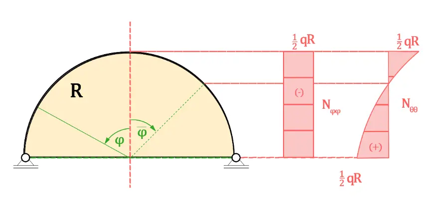
Consider a spherical shell subjected to uniformly distributed planform load $$q$$, as illustrated in Figure 1a. The surface-load components read [21] $${P}_{\varphi }=q\mathrm{c}\mathrm{o}\mathrm{s}\varphi \mathrm{s}\mathrm{i}\mathrm{n}\varphi$$, $${P}_{z}=-q{\mathrm{c}\mathrm{o}\mathrm{s}}^{2}\varphi$$. The resulting membrane-force-flow distributions are:
Profiles for $${N}_{\varphi \varphi }$$ and $${N}_{\theta \theta }$$ are plotted in Figure 1a. Notably, $${N}_{\varphi \varphi }$$, maintains a constant value $$-qR/2$$ along the meridian and is independent of angle $$\varphi$$. By contrast, $${N}_{\theta \theta }$$ varies circumferentially and reverses its sign at $$\varphi =45°$$ [21].
Our group previously reported a membrane-force analysis for liquid layers beneath capillary menisci in cylindrical tubes [20]. When the weight of liquid beneath the capillary meniscus is treated as the applied distributed load, the Young-Laplace surface tension relation $$\gamma =∆pR/2$$ shares identical mathematical form with the meridian membrane-force-flow expression $${N}_{\varphi \varphi }=-qR/2$$ for uniformly loaded spherical shells. Experimental evidence confirms that gravity-governed capillary menisci of pure liquids closely approximate spherical surfaces with a unique curvature radius, irrespective of pipe diameter [20].
Two consistency conditions link capillary-meniscus force balance to uniformly-loaded spherical-shell mechanics: (1) both geometries adopt spherical surfaces; (2) external loads are balanced by tangential membrane forces acting on curved spherical surfaces with matching analytical expressions. Accordingly, liquid layers beneath a capillary meniscus can be treated in the sense of structural mechanics membranes, transmitting forces purely via in-plane tension or compression without bending moments, torques, or transverse shear forces. The present study extends this membrane-force modelling framework to analyze internal forces within laminar circular-tube flow.
 |
|
(a) |
 |
|
(b) |
 |
|
(c) |
 |
|
(d) |
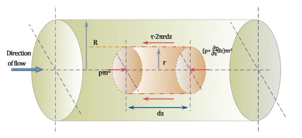
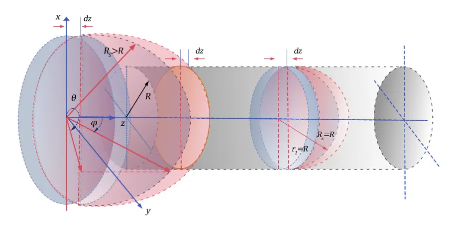
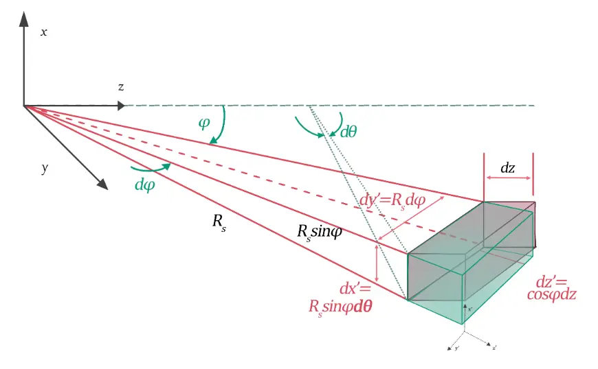
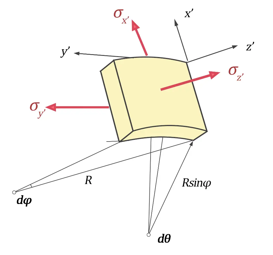
Figure 1. Laminar spherical fluid layers in a pipe and the microelement for force analysis. (a) A spherical shell under a load $$q$$ uniformly distributed over the planform [21]. The distributions of the membrane force flow $${N}_{\varphi \varphi }$$ and $${N}_{\theta \theta }$$ are given as: $${N}_{\varphi \varphi }=-\frac{qR}{2}$$, $${N}_{\theta \theta }=-\frac{qR\mathrm{c}\mathrm{o}\mathrm{s}2\varphi }{2}$$. (b) Steady laminar and incompressible flow through pipe [22]. The flow direction is defined as the z-direction. Laminar-flow conditions: $${u}_{r}={u}_{\theta }=0$$, $${u}_{z}\left(r\right)={u}_{0}\left(1-\frac{{r}^{2}}{{R}^{2}}\right)$$, $${u}_{0}=-\frac{{R}^{2}}{4\mu }\frac{\partial p}{\partial z}$$, with $$\frac{\partial p}{\partial z}<0$$. Wall shear stress at $$r=R$$: $${\tau }_{w}=\mu {\frac{du}{dr}|}_{r=R}=-\frac{2\mu {u}_{0}}{R}$$. (c) Spherical-shell-shaped fluid layers with stream-wise thickness $$dz$$. $${R}_{S}$$ denotes the single curvature radius of the virtual layer, $${R}_{S}\ge R$$, subscript $$S$$ denotes “spherical”. (d) A differential element of a spherical shell in local $${x}^{\prime}{y}^{\prime}{z}^{\prime}$$ coordinates, where $$d{z}^{\prime}=\mathrm{c}\mathrm{o}\mathrm{s}\varphi dz$$, $${dx}^{\prime}=rd\theta ={R}_{S}\mathrm{s}\mathrm{i}\mathrm{n}\varphi d\theta$$, $$d{y}^{\prime}={R}_{S}d\varphi$$. Force flows in the $${x}^{\prime}-$$ and $${y}^{\prime}-$$coordinates correspond to $${\gamma }_{\theta \theta }$$ and $${\gamma }_{\varphi \varphi }$$ respectively, pressure in the $${z}^{\prime}$$-direction equals $${\sigma }_{{z}^{\prime}}=p\left(z\right)$$.
Steady, incompressible laminar pipe flow (Figure 1b) can be described by Newton’s viscosity law and Newton’s second law of motion [22]. Force equilibrium establishes a balance between the pressure difference force acting on the two end-faces of a fluid element and opposing viscous shear forces exerted along its lateral cylindrical surface. Flow proceeds along the z-direction. Under laminar conditions, radial and azimuthal velocities vanish: $${u}_{r}={u}_{\theta }=0$$. The axial velocity profile follows the parabolic Poiseuille solution:
Average velocity is $$\bar{u}={u}_{0}/2$$. The conventional pipe-flow Reynolds number $$\mathrm{R}\mathrm{e}=\rho D\bar{u}/\mu$$ is equivalent to $$\mathrm{R}\mathrm{e}=\rho R{u}_{0}/\mu$$, using $$D=2R$$, $$\bar{u}={u}_{0}/2$$. Wall shear stress reads:
The negative sign indicates that shear stress points opposite to the positive z-direction.
Force balance for rigid cylindrical bodies is straightforward to interpret. However, the fluid element in Figure 1b is deformable. While rigid-body static equilibrium axioms [23] can be formally applied to steady-state deformable fluid volumes, alternative force-equilibrium treatments are still desirable.
Consider a spherical-shell-shaped fluid layer oriented along the stream-wise direction with infinitesimal stream-wise thickness $$dz$$ (Figure 1c). The pressure-gradient force across this circular layer acts as a distributed transverse load $$q=-\frac{\partial p}{\partial z}dz.$$ We then apply spherical-shell membrane-force flow theory to this virtual fluid shell.
The physical motivation for adopting the spherical-shell membrane-force analogy is two-fold. First, the virtual spherical shell mediates transmission of cross-sectional pressure-gradient forces to the pipe wall and balances these loads against circumferential viscous forces. Second, internal membrane-type forces within the virtual shell act tangentially to the spherical surface. Their stream-wise components balance pressure-gradient loads, and components perpendicular to the stream-wise direction generate forces exchanged between fluid and pipe wall. This wall-interacting force component has received limited attention within classical fluid-mechanics literature. For pipe-flow transition conditions, the tangential direction of the virtual spherical shell coincides with the pipe-wall tangential direction at the solid boundary. Consequently, the critical tensile force flow at the pipe wall numerically matches the critical wall shear stress reported in polymer-solution early-turbulence experiments [10]. It is stated that this analogy is purely mathematical and force-balance-based. The virtual spherical fluid shell inside single-phase pipe flow has no real interfacial surface tension; it serves only as a conceptual tool to reorganize internal fluid-force components.
The meridian membrane-force flow component is:
where $${R}_{S}$$ represents the curvature radius of this virtual, spherical liquid layer. Substituting the center-line Poiseuille-flow relation $${u}_{0}=-\frac{{R}^{2}}{4\mu }\frac{\partial p}{\partial z}$$, membrane-force flow components become:
We define tensile force flow by normalizing membrane-force flows against shell thickness dz:
Here $${\gamma }_{\varphi \varphi }$$ and $${\gamma }_{\theta \theta }$$ are tensile-force flow quantities along meridian and circumferential directions of $$\varphi$$ and $$\theta$$, respectively. Symbol $$\gamma$$ is borrowed from surface-tension notation. The unit of membrane force flow $${N}_{\varphi \varphi }$$ in structure mechanics is N/m, since it represents the integral result of stress (N/m2) over the thickness of the membrane [21]. In the spherical-shell-shaped fluid layer model, the thickness of the layer is dz. $${\gamma }_{\varphi \varphi }={N}_{\varphi \varphi }/dz$$, then the unit of tensile fore flow $${\gamma }_{\varphi \varphi }$$ is N/m2. The unit of $${\gamma }_{\varphi \varphi }$$ is identical with that of the shear stress, and we can see the difference between these two later.
Figure 1d illustrates a liquid micro-element described within local coordinates, with differential lengths $$d{x}^{\prime}={R}_{S}\mathrm{s}\mathrm{i}\mathrm{n}\varphi d\theta$$, $$d{y}^{\prime}={R}_{S}d\varphi$$, $$d{z}^{\prime}=\mathrm{c}\mathrm{o}\mathrm{s}\varphi dz$$. Its volume is $${R}_{S}^{2}\mathrm{s}\mathrm{i}\mathrm{n}\varphi \mathrm{c}\mathrm{o}\mathrm{s}\varphi d\theta d\varphi dz$$. An important issue that needs to be explained here is that the local rectangular $${x}^{\prime}{y}^{\prime}{z}^{\prime}$$ coordinate system at any microelement is uniquely fixed, which is only determined by local axial forces (presenting as pressure or tension), in directions of meridian and ring, without effects from any bending moments, torques, or shear forces. The stresses acting on a liquid microelement in $$d{x}^{\prime}$$, $$d{y}^{\prime}$$, and $$d{z}^{\prime}$$ directions are $${\sigma }_{{x}^{\prime}}$$, $${\sigma }_{{y}^{\prime}}$$, and $${\sigma }_{{z}^{\prime}}$$, in material mechanics. Stress is defined as force per unit area; resultant force is obtained by integrating stress over area.
2.2. Derivation of a Candidate Critical Tensile-Force-Flow Criterion for Transition of Pipe Poiseuille Flow
Rearranging Equation (6), the curvature radius $${R}_{S}$$ of the virtual spherical-shell liquid layer is:
At low flow velocity, axial pressure gradients remain small; hence, the virtual-shell curvature radius $${R}_{S}$$ is much larger than the physical pipe radius R, corresponding to the left-hand virtual spherical shell in Figure 1c, $${R}_{S}\ge R$$. In the limiting case of zero flow velocity and vanishing pressure gradient, $${R}_{S}$$ tends toward infinity. As flow velocity and Reynolds number increase if other parameters remain unchanged, the axial pressure gradient grows and $${R}_{S}$$ decreases. Our core hypothesis states: laminar-flow structural collapse (transition onset) is postulated to occur once the virtual-shell curvature radius shrinks to match the physical pipe radius, i.e., $$R={R}_{S}.$$ In this case,
Solving for the tensile force flow:
Here, $${\gamma }_{\nu }$$ denotes the hypothesized critical tensile force flow when $$R={R}_{S}$$,$$\,\mathrm{t}\mathrm{h}\mathrm{i}\mathrm{s}\mathrm{ }\,\mathrm{v}\mathrm{a}\mathrm{l}\mathrm{u}\mathrm{e}$$ equals the magnitude of wall shear stress [10] as $${\tau }_{w}=-2\mu {u}_{0}/R$$. Symbol $${\gamma }_{\nu }$$ uses subscript $$\nu$$ only as a label for critical tensile force flow; this subscript does not denote kinematic viscosity $$\nu =\mu /\rho$$. This result suggests that for a given Newtonian fluid, the maximum pipe radius sustaining laminar motion scales proportionally with center-line velocity $${u}_{0}$$. We emphasize that Equation (10) represents a candidate transition parameter derived from a conceptual virtual-shell membrane-force model; it is not experimentally proven as a universal material constant. This prediction diverges qualitatively from classical Reynolds-number-based reasoning. According to the Reynolds-number criterion, flows combining a large center-line velocity $${u}_{0}$$ with small pipe radius R can theoretically remain laminar at fixed Re. By contrast, our virtual-shell hypothesis indicates that high $${u}_{0}$$ paired with small pipe radius compresses $${R}_{S}$$ and may trigger laminar structural collapse. This quantity serves as a Newtonian hydrodynamic baseline hypothesis requiring further experimental testing.
To provide an intuitive qualitative picture for the virtual-spherical-shell hypothesis, consider a circular rigid ring spanned by an elastic rubber-like membrane. When no transverse load is applied, the membrane lies flat, corresponding to an infinite radius of curvature. Under transverse pressure loading (analogous to the axial pressure gradient in pipe flow), the membrane deforms into a concave spherical-shell geometry, and its curvature radius progressively decreases as the applied load increases, assuming sufficient membrane extensibility. A critical condition is reached when the membrane’s curvature radius shrinks to match the geometrical radius of the supporting ring. Beyond this point, a stable spherical-shell configuration can no longer be sustained, and membrane failure occurs. We draw a qualitative analogy between this membrane-failure scenario and laminar-to-turbulent transition in pipe flow: the breakdown of the hypothetical virtual spherical fluid shell corresponds to the onset of disordered turbulent flow.
It should be emphasized that the stretching-driven failure of a solid elastic membrane is not physically identical to the behavior of a Newtonian viscous fluid. For elastic solids, deformation is reversible; removing the applied load allows the membrane to recover its original flat geometry. For Newtonian fluids such as water, viscous deformation persists only under sustained loading. When the driving pressure gradient vanishes, fluid motion ceases, but there is no elastic restorative rebound back to a prior deformed state.
Within our conceptual framework, pipe-flow pressure-gradient loading generates non-zero shear vectors and builds up accumulated tensile-mode energy within the near-wall fluid layer [24]. We advance a tentative hypothesis: localized breakdown of laminar flow is triggered once the build-up of this fluid-borne tensile energy reaches a limiting threshold, and the subsequent release of accumulated tensile-associated energy constitutes an energy source for the onset of soliton/like coherent structures (SCS) accompanying laminar-turbulent transition [25]. This physical hypothesis remains qualitative and awaits rigorous experimental validation. Further fundamental investigations are required to characterize the nature and magnitude of tensile-type internal actions within viscous fluid flows.
2.3. Comparison with Traditional Critical Reynolds Number for Dividing Flow Regions
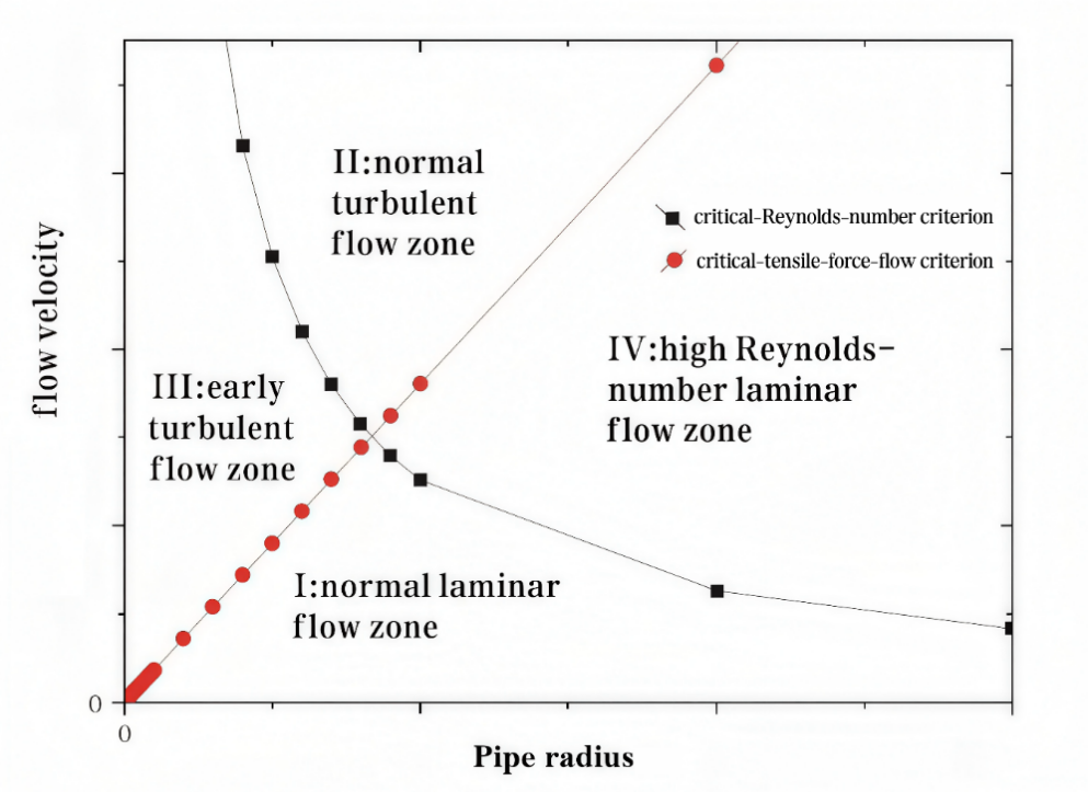
Equation (10) yields the relation between laminar transition velocity and pipe-radius, illustrated in Figure 2a. Red circles and black squares denote trends predicted respectively by our theoretical model and by the critical-Reynolds-number framework, dividing the parameter plane into four zones. If transition is judged purely via critical-Reynolds-number criterion: Zones I and III are laminar, Zones II and IV are turbulent. If judged using our candidate critical-tensile-force-flow criterion: Zones I and IV are laminar, Zones II and III are turbulent. Zones I and II receive consistent classification under both viewpoints. Zones III and IV yield contradictory classifications. Whether our critical-tensile-force-flow-based partitioning can exhibit better qualitative consistency with the two anomalous flow phenomena introduced in Section 1 will be elaborated in Section 3.
 |
|
(a) |
 |
|
(b) |
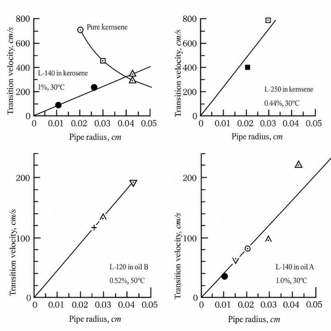
Figure 2. The relationship between the transition velocity of laminar flow and the radius of the pipe. (a) Schematic diagram contrasting transition velocity versus pipe radius for two cases. Red circles: trend derived from the present critical-tensile-force-flow criterion; black squares: trend inferred from classical critical-Reynolds-number criterion. These points are theoretical schematic sampling points, not experimental measurements. Figure 2a is a conceptual schematic diagram without quantitative axis scales. Two curves partition the parameter space into four zones I–IV. Zone I: laminar flow; Zone II: turbulent flow; Zone III: predicted laminar according to critical-Reynolds-number criterion but observed as early turbulence in experiments [10]; Zone IV: predicted turbulent by critical-Reynolds-number criterion but achievable as laminar via active wall suction [16]. (b) Reproduced experimental early-turbulence data for different polymer-solution systems; transition velocity scales linearly with pipe radius and extrapolates toward the origin, consistent with critical-shear-stress-controlled structural-turbulence onset reported in literature [10].
3. Two Types of Flow Phenomena Explained by the Critical Tensile Force Flow
3.1. Early Turbulence
Zone III in Figure 2a corresponds to the well-documented early turbulence (termed structural turbulence) regime reported in prior literature [7,8,9,10,14,15,26], characterized by a well-defined critical wall shear-stress magnitude. Figure 2b reproduces published structural-turbulence experimental data, which is figure 7 of ref. [10] reproduced here after permission, plotting transition velocity against pipe radius yields straight-line behavior extrapolating to the origin, matching the qualitative trend from our model shown in Figure 2a. It was stated in ref. [10] that the turbulence characterized by Re is characterized by a hyperbolic curve, and the average flow velocity is proportional to the reciprocal of the radius, $${\bar{U}}_{c}\propto 1/R$$, and proportional to the viscosity, $${\bar{U}}_{c}\propto \mu$$. Structural/early turbulence, however, is characterized by a critical shear stress, $${\tau }_{c}$$, at the wall of the capillary, which has a typical value for every substance. This critical shear stress indicates a collapse of the structure of the fluid. In this case, the average flow velocity is proportional to the radius, $${\bar{U}}_{c}\propto R$$, and proportional to the reciprocal of the viscosity, $${\bar{U}}_{c}\propto 1/\mu$$. It was further stated in [10] that, as the product $${\bar{U}}_{c}R$$ appears in Reynolds number, it is obvious that $${\mathrm{R}\mathrm{e}}_{c}$$, in the case of structural turbulence, varies as $${R}^{2}$$. On plotting the transition velocity versus the pipe radius, structural turbulence is described by a straight line extrapolated to the origin, as shown in Figure 2b, being obviously predicted in Figure 2a. It was further concluded that the critical-Reynolds-number criterion loses its significance as a criterion for structural turbulence [10], and that structural turbulence is generally detected only in pipes of small diameter where the high shear stresses needed to produce the effect can be reached below the transition Reynolds number for Reynolds turbulence [26]. It was suggested that the wall shear stress, which characterizes the onset of structural turbulence, is roughly independent of tube diameter [10,26].
The critical tensile force flow is not yet treated here as an intrinsic material property of polymer solutions. Instead, it represents a Newtonian hydrodynamic baseline threshold describing the near wall tensile limit for structural collapse of laminar Poiseuille flow for purely Newtonian fluids. When applied to viscoelastic polymer solution experimental data, it serves as a reference hydrodynamic benchmark. Real experimental onset values for early turbulence in polymer solutions can deviate from this Newtonian baseline; such deviations are attributed to polymer originated viscoelastic and molecular effects (polymer relaxation, molecular aggregation, network formation/breakup), which are external to our Newtonian derivation.
3.2. High-Reynolds-Number Laminar Flow
The virtual-larger-pipe interpretation presented below is an approximate conceptual analysis, not a rigorous derivation from suction-modified Navier-Stokes equations. Rigorous treatment incorporating suction boundary-conditions, disturbance-energy budgets, and stability analysis remains for future work.
Zone IV, shown in Figure 2a, represents high-Reynolds-number laminar flow stabilized by wall suction, which can sustain laminar conditions up to 20 × 106 [16,17,18]. This phenomenon can be analyzed using the conceptual virtual-spherical-shell model visualized in Figure 3.
 |
|
(a) |
 |
|
(b) |
 |
|
(c) |
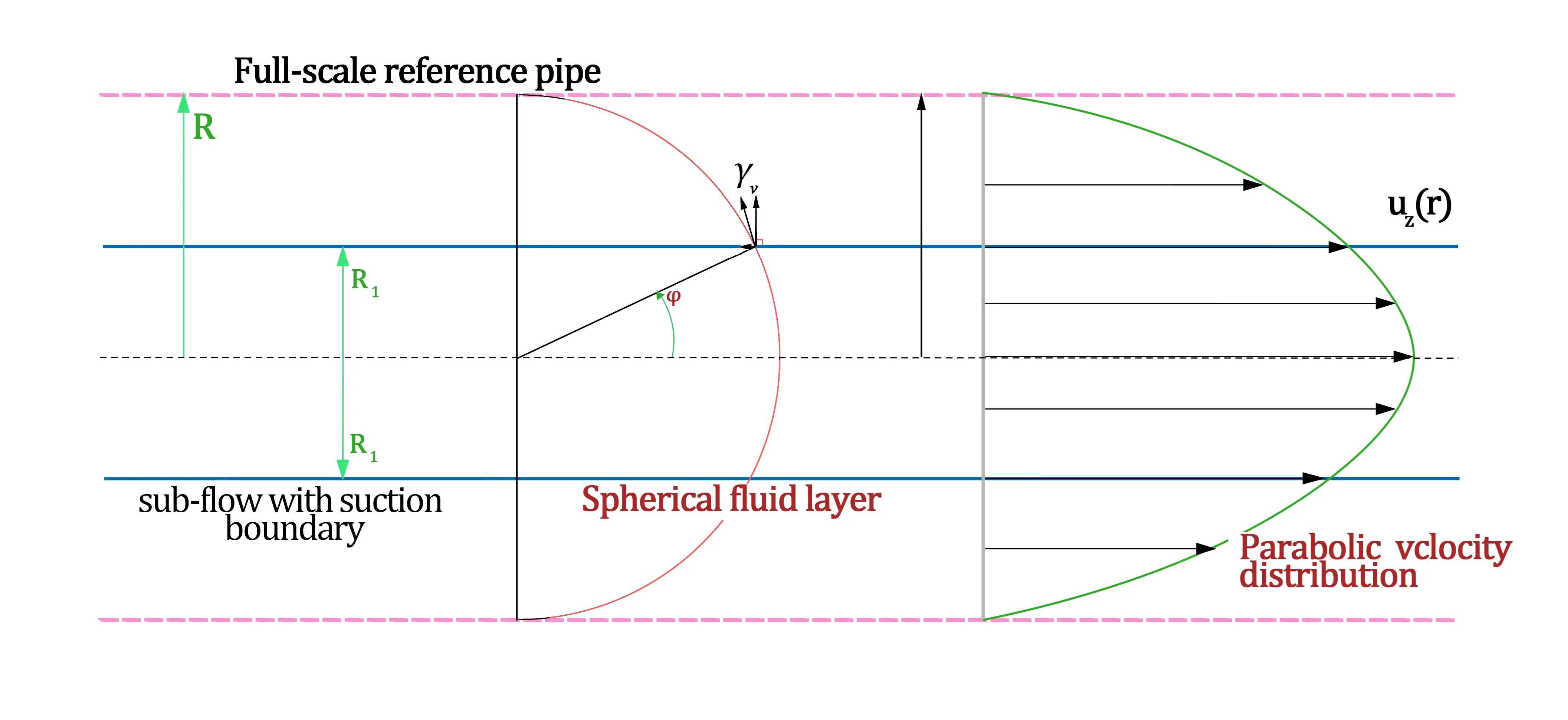
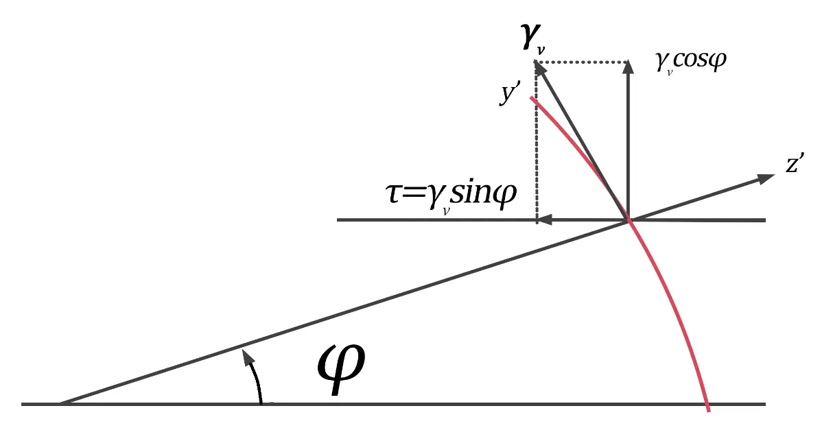
Figure 3. Conceptual model for high-Reynolds-number laminar flow. (a) No-slip pipe-flow at hypothesized transition condition, where virtual-shell curvature radius equals physical pipe radius $${R}_{\mathrm{S}}=R$$. A high-Reynolds number laminar flow inside a smaller radius pipe $${R}_{1}<=R={R}_{\mathrm{S}}\,$$can be conceptualized as a sub-region of this full-scale reference pipe. (b) Wall shear stress $$\tau$$ constitutes a directional component of critical-tensile-force flow $${\gamma }_{\nu }$$: $$\tau ={\gamma }_{\nu }\mathrm{s}\mathrm{i}\mathrm{n}\varphi .$$ When $$\varphi =90°$$, wall shear stress at transition $$R={R}_{\mathrm{S}}$$ equals $${\tau }_{w,c}={\gamma }_{\nu }$$. (c) Micro-element within local $${x}^{\prime}{y}^{\prime}{z}^{\prime}$$ coordinate system, where $${\sigma }_{{x}^{\prime}}, {\sigma }_{{y}^{\prime}}$$ are related to$$\mathrm{ }{\gamma }_{\nu }$$, respectively, and $${\sigma }_{{z}^{\prime}}=p\left(z\right)$$.
Consider a reference no-slip pipe-flow case at a hypothesized transition state with $$R={R}_{\mathrm{S}}$$. Imagine a sub-flow domain with a smaller physical radius $${R}_{1}<R={R}_{\mathrm{S}}$$ embedded within this reference pipe. The unmodified Poiseuille velocity profile reads $${u}_{z}\left(r\right)={u}_{0}\left(1-\frac{{r}^{2}}{{R}^{2}}\right)$$. At the radial position $${R}_{1}$$, local fluid velocity is written as $${u}_{{R}_{1}}={u}_{0}{\mathrm{c}\mathrm{o}\mathrm{s}}^{2}\varphi .$$ As illustrated in Figure 3b, wall-parallel shear stress component becomes:
Equation (11) demonstrates that wall suction reduces real-wall shear-stress magnitude by a factor of $$sin\varphi$$, producing a drag-reduction-like effect. For fixed pipe geometry and bulk-flow conditions, raising near-wall fluid velocity via wall-suction decreases resultant wall shear-stress while preserving laminar flow.
So far, our discussion has considered impermeable-wall laminar pipe flow at the hypothesized laminar-to-turbulent transition condition, where the curvature radius of the virtual spherical fluid shell equals the physical pipe radius, and the tensile force flow attains its critical value $${\gamma }_{\nu }$$. We now examine the local flow domain bounded by a virtual inner radius $${R}_{1}$$, where $${R}_{1}<R$$. The local axial fluid velocity at radial position $${R}_{1}$$ is:
Consider inserting a mass-less cylindrical sleeve at $$r={R}_{1}$$, which translates coaxially at exactly the local fluid velocity $${u}_{{R}_{1}}$$. The outer flow field for $${r>R}_{1}$$ remains completely undisturbed by this moving sleeve. We next replace this hypothetical moving sleeve with a stationary physical pipe wall placed at $$r={R}_{1}$$. When wall suction is applied such that the fluid velocity on this stationary wall matches $${u}_{{R}_{1}},$$ the inner flow field $$\left(r<{R}_{1}\right)$$ can be approximately preserved. This treatment constitutes an approximate conceptual analysis. Provided the wall-suction boundary condition is adequately realized experimentally, the real flow can approach this idealized reference state.
The average flow velocity inside $${R}_{1}<{R=R}_{\mathrm{S}}$$ evaluates to:
Given the measured average velocity $${\overline{u}}^{\prime}$$ for high-Reynolds-number laminar flow, the angle parameter $$\varphi$$ can be solved:
The high Reynolds-number value (Re$$\,\approx\,$$20 × 106) reported for suction-stabilized laminar flow [16,17,18] is computed as $${\mathrm{R}\mathrm{e}}_{\mathrm{c}}=2\rho {R}_{1}{\overline{u}}^{\prime}/\mu .$$ Experimental datasets for fully laminar pipe runs are extracted from published suction-controlled experiments and compiled in Table 1 [16]. The length Re has not been considered here. From tabulated $${\overline{u}}^{\prime}$$ and $${u}_{0}/{\overline{u}}^{\prime}$$ from reference data [16], we solve for virtual reference-pipe radius $$R={R}_{\mathrm{S}}$$ and angle $$\varphi$$. Most computed $$\varphi$$ values cluster near 45°, coinciding with the angle where $${N}_{\theta \theta }$$ reverses its sign in spherical-shell membrane theory [21]. We conjecture this feature may correlate with localized transition onset. This remains speculative and will be elaborated in Part II of this series [24]. We further calculate the virtual-pipe Reynolds-number $${\mathrm{R}\mathrm{e}}_{\mathrm{v}}=\rho R{u}_{0}/\mu$$, as shown in Table 1. The virtual-pipe Reynolds-number approximates the classical critical Reynolds-number $${\mathrm{R}\mathrm{e}}_{\mathrm{c}}$$, as a larger virtual-pipe radius and reduced center-line velocity exert counter-acting effects. Critical-tensile-force-flow values are also summarized within Table 1. Calculations in Table 1 serve only for qualitative illustration; limited scattered data cannot confirm $${\gamma }_{\nu }$$ as universal constant. Among five experimental entries from reference data, four entries yield moderately scattered values near 0.040, while one dataset deviates substantially. Real physical-wall shear-stress $$\tau$$, following Equation (11), is always smaller than $${\gamma }_{\nu }$$.
It is emphasized that our work contributes an alternative physical framework for laminar-turbulent transition, rather than claiming final proof of a universal material parameter. Further well controlled experimental measurements covering broader ranges will be required to validate or falsify whether this threshold can be generalized.
Table 1. Calculation of flow parameters for a virtual pipe from the original data [16].
|
$${\bm{R}}_{1}\left(\mathbf{m}\right)$$ |
$${\overline{\bm{u}}}^{\mathbf{\prime}}$$ |
$$\frac{{\overline{\bm{u}}}^{\mathbf{\prime}}{\bm{R}}_{1}}{\bm{\nu }}$$ |
```latex\frac{{\bm{u}}_{0}}{{\overline{\bm{u}}}^{\mathbf{\prime}}}``` |
$$\mathbf{R}\mathbf{e}$$ |
$${\bm{u}}_{0}$$ |
$$\mathbf{sin}\bm{\varphi }$$ |
$$\bm{\varphi }\left(°\right)$$ |
$$\bm{R}\left(\bm{m}\right)$$ |
$${\mathbf{R}\mathbf{e}}_{\bm{v}}$$ |
$${\bm{\gamma }}_{\bm{\nu }}$$ |
$$\bm{\tau }$$ |
|---|---|---|---|---|---|---|---|---|---|---|---|
|
0.0254 |
30.5 |
50,050 |
1.3 |
100,100 |
39.8 |
0.68 |
43 |
0.037 |
95,580 |
0.041 |
0.028 |
|
0.0254 |
26.66 |
44,200 |
1.3 |
88,400 |
35.9 |
0.72 |
46 |
0.035 |
82,919 |
0.039 |
0.028 |
|
0.0254 |
25.04 |
41,470 |
1.4 |
82,940 |
35.0 |
0.75 |
49 |
0.034 |
76,845 |
0.040 |
0.030 |
|
0.0129 |
51 |
44,000 |
1.5 |
88,000 |
77.2 |
0.82 |
55 |
0.016 |
80,834 |
0.181 |
0.151 |
|
0.0254 |
30 |
49,600 |
1.4 |
99,200 |
42.3 |
0.76 |
50 |
0.033 |
91,707 |
0.049 |
0.037 |
4. Conclusions
This paper analyses internal force structures within laminar pipe Poiseuille flow and puts forward a hypothesis describing laminar-to-turbulent transition built upon a virtual spherical-shell membrane-force analogy. Some important property parameters are summarized in Table 2. The main findings and hypotheses are summarized below:
- (1)
-
Treating axial pressure-gradient load as a distributed transverse load over cross-sections, we construct a conceptual force model for a constant-thickness spherical-shell virtual fluid layer inside circular pipe flow, adopting structural-mechanics spherical-shell membrane-force theory. Radial membrane-force-flow quantities are obtained as products between the transverse pressure-gradient load and virtual-shell curvature radius $${R}_{S}$$. This virtual shell is a conceptual diagnostic tool rather than a real material interface.
- (2)
-
As Reynolds-number increases, the axial pressure-gradient magnitude rises, and the curvature radius $${R}_{S}$$ of the virtual spherical-shell fluid layer decreases. We hypothesize that laminar-flow structural collapse (transition onset) may take place when $${R}_{S}$$ decreases to or below the physical pipe radius R. Under this hypothesized transition condition, we derive the candidate critical-tensile-force-flow expression: $${\gamma }_{\nu }=2\mu {u}_{0}/R$$.
- (3)
-
Wall shear-stress constitutes the stream-wise component of tensile-force-flow. At the hypothesized transition condition, wall-shear-stress magnitude numerically equals $${\gamma }_{\nu }$$. This qualitative behavior shows consistency against published early-turbulence experimental observations. We emphasize explicitly that $${\gamma }_{\nu }$$ represents a candidate Newtonian hydrodynamic baseline threshold; it has not been established as a universal intrinsic-fluid-material constant. Currently available experimental data are limited; generalization demands further well-controlled experimental verification.
- (4)
-
The critical-tensile-force-flow framework supplies a qualitative physical interpretation for high-Reynolds-number laminar flow sustained by wall suction. Physical pipe geometry can be conceptually regarded as a subsection of a larger hypothetical virtual pipe satisfying critical-tensile-force-flow conditions. Wall-suction lowers real-wall shear-stress by a factor of $$\mathrm{sin}\varphi$$, suppressing laminar structural-collapse even under very high bulk Reynolds numbers. This is an approximate conceptual picture, not rigorous derivation from suction boundary-value problem.
The next step in the work is to establish a new viscous fluid motion equation based on stresses and their distribution in general fluid motion. Modern research on pipe flow transition explicitly takes into account finite amplitude perturbations, transient growth, local turbulence structures, and the subcritical characteristics of the transition. By integrating these more in-depth research methods and approaches with the concept of critical-tensile-force flow, it is possible to deepen our understanding of turbulence occurrence and evolution.
Table 2. Nomenclature summary for some important parameters.
|
Symbol |
Term |
Physical Dimension |
SI Unit |
Physical Meaning & Key Distinction |
|---|---|---|---|---|
|
$$\bm{p}$$ |
Hydrostatic pressure |
ML−1T−2 |
Pa (N·m−2) |
Isotropic compressive point-wise stress acting normal to surfaces. In pipe Poiseuille flow, the stream-wise pressure gradient $$-\partial p/\partial z\,$$drives bulk fluid motion. |
|
$${\bm{\tau }}_{\bm{i}\bm{j}}$$ |
Total fluid stress tensor |
ML−1T−2 |
Pa |
Full stress tensor of flowing fluid. Decomposed into isotropic pressure $$p$$, viscous shear-stress components $${\tau }_{ij}^{\mathrm{v}\mathrm{i}\mathrm{s}\mathrm{c}}$$, and visco-elastic extra-stress contributions $${\tau }_{ij}^{\mathrm{e}\mathrm{x}\mathrm{t}\mathrm{r}\mathrm{a}}$$ for polymer-solution flows. |
|
$${\bm{\tau }}_{\bm{w}}$$ |
Wall shear stress |
ML−1T−2 |
Pa |
Tangential (off-diagonal tensor component) viscous stress exerted at the pipe wall. Major experimental observable for the onset of early-/structural-turbulence in dilute polymer solutions. Acts parallel to a solid boundary; it is fundamentally different from normal/tensile stress. |
|
$${\bm{\sigma }}_{\bm{i}\bm{i}}$$ |
Extra normal stress (viscoelastic normal stress difference) |
ML−1T−2 |
Pa |
Diagonal stress-tensor components acting perpendicular to material planes. Zero for Newtonian fluids; non-zero first-/second-normal-stress differences arise from stretched polymer macromolecules in viscoelastic dilute polymer solutions. Can be tensile (positive) or compressive (negative); not equivalent to hydrostatic pressure. |
|
$${\bm{N}}_{\bm{\varphi }\bm{\varphi }}$$ |
Membrane force flow |
MT−2 |
N·m−1 |
Force flows are obtained by multiplying the plane stress components by the shell thickness, and as a result, the dimension of force flows is force per unit length, which is identical to the dimension of surface tension in fluid mechanics. |
|
$${\bm{\gamma }}_{\bm{\nu }}$$ |
Critical tensile force flow, this work |
M L−1T−2 |
N·m−2 |
Tensile force flow is delivered from the membrane force flow for the Newtonian laminar Poiseuille flow, and the critical tensile force flow is got as the laminar-flow structure collapses. For polymer-solution experiments it serves as a reference benchmark, not an intrinsic material constant. |
Statement of the Use of Generative AI and AI-Assisted Technologies in the Writing Process
During the preparation of this manuscript, the author used [Doubao] in order to [obtain suggestions for revising the paper based on the reviewer's comments, as well as suggestions for responding to the reviewer's comments]. After using the tool, the author reviewed and edited the content as needed and takes full responsibility for the content of the published article.
Author Contributions
Conceptualization, H.Z.; Methodology, H.Z. and Y.Y.; Data Curation, Y.Y.; Writing—Original Draft Preparation, H.Z. and Y.Y.; Writing—Review & Editing, H.Z.; Visualization, H.Z. and Y.Y.; Supervision, H.Z.; Project Administration, H.Z.; Funding Acquisition, H.Z.
Ethics Statement
Not applicable.
Informed Consent Statement
Not applicable.
Data Availability Statement
The data may be obtained from the author upon reasonable request.
Funding
This research was funded by the High-level Talent Introduction Plan of Xihua University, grant number [ZX20250126]. Y.Y. acknowledges the financial support from the Special Project for the Construction of Research Bases (Interdisciplinary Research on Frontiers of Applied Mechanics) of the Fundamental Research Funds for the Central Universities, China University of Mining and Technology, grant number [2024KYJD1013].
Declaration of Competing Interest
The author declares that there is no conflict of interest.
References
- Eckert M. Pipe flow: A gateway to turbulence. Arch. Hist. Exact Sci. 2020, 75, 249–282. DOI:10.1007/s00407-020-00263-y [Google Scholar]
- Avila M, Barkley D, Hof B. Transition to Turbulence in Pipe Flow. Annu. Rev. Fluid Mech. 2023, 55, 575–602. DOI:10.1146/annurev-fluid-120720-025957 [Google Scholar]
- Barkley D. Theoretical perspective on the route to turbulence in a pipe. J. Fluid Mech. 2016, 803, P1. DOI:10.1017/jfm.2016.465 [Google Scholar]
- Rott N. Note on the History of the Reynolds Number. Annu. Rev. Fluid Mech. 1990, 22, 1–11. DOI:10.1146/annurev.fl.22.010190.000245 [Google Scholar]
- Mullin T. Experimental Studies of Transition to Turbulence in a Pipe. Annu. Rev. Fluid Mech. 2011, 43, 1–24. DOI:10.1146/annurev-fluid-122109-160652 [Google Scholar]
- Dou HS, Zhao H. Turbulent Transition Criteria: From Reynolds Experiment to Modern Numerical Methods. Int. J. Turbul. Explor. 2026, 1, 10001. DOI:10.70322/ijte.2026.10001 [Google Scholar]
- Forame PC, Hansen RJ, Little RC. Observations of early turbulence in the pipe flow of drag reducing polymer solutions. AIChE J. 1972, 18, 213–217. DOI:10.1002/aic.690180139 [Google Scholar]
- Hansen RJ, Little RC, Forame PG. Experimental and Theoretical Studies of Early Turbulence. J. Chem. Eng. Jpn. 1973, 6, 310–314. DOI:10.1252/jcej.6.310 [Google Scholar]
- Hansen RJ, Little RC. Early turbulence and drag reduction phenomena in larger pipes. Nature 1974, 252, 690–690. DOI:10.1038/252690a0 [Google Scholar]
- Ram A, Tamir A. Structural turbulence in polymer solutions. J. Appl. Polym. Sci. 1964, 8, 2751–2762. DOI:10.1002/app.1964.070080621 [Google Scholar]
- Groisman A, Steinberg V. Elastic turbulence in a polymer solution flow. Nature 2000, 405, 53–55. DOI:10.1038/35011019 [Google Scholar]
- Manfield PD, Lawrence CJ, Hewitt GF. Drage Reduction with Additives in Multiohase Flow: A Literature Survey. MultScienTechn 1999, 11, 197–221. DOI:10.1615/MultScienTechn.v11.i3.20 [Google Scholar]
- Virk PS. Drag reduction fundamentals. AIChE J. 1975, 21, 625–656. DOI:10.1002/aic.690210402 [Google Scholar]
- Virk PS. The Toms Phenomenon—Turbulent Pipe Flow of Dilute Polymer Solutions. Ph.D. Thesis, Massachuseits Institute of Technology, Cambridge, MA, USA, November, 1966. [Google Scholar]
- Virk PS, Merrill EW, Mickley HS, Smith KA. The Critical Wall Shear Stress for Reduction of Turbulent Drag in Pipe Flow. In Proceedings of the International Conference on Rheology, Pinebrook Conference Center of Syracuse University, Pinebrook, New York, NY, USA, 23–27 August 1965. [Google Scholar]
- Pfenninger W. Boundary Layer Suction Experiments with Laminar Flow at High Reynolds Numbers in the Inlet Length of a Tube by Various Suction Methods. In Boundary Layer and Flow Control, Its Principles and Application; Lachmann GV, Ed.; Pergamon: Oxford, UK, 1961; pp. 961–980. DOI:10.1016/B978-1-4832-1323-1.50013-0 [Google Scholar]
- Braslow AL, Visconti F. Further Experimental Studies of Area Suction for the Control of the Laminar Boundary Layer on a Porous Bronze NACA 64A010 Airfoil. National Advisory Committee for Aeronautics. 1950. Available online: https://scispace.com/pdf/further-experimental-studies-of-area-suction-for-the-control-1zgmeenvjo.pdf (accessed on 27 September 2026).
- Braslow AL, Burrows DL, Tetervin N, Visconti F. Experimental and Theoretical Studies of Area Suction for the Control of the Laminar Boundary Layer on an NACA 64A010 Airfoil. National Advisory Committee for Aeronautics. 1951. Available online: https://scispace.com/pdf/experimental-and-theoretical-studies-of-area-suction-for-the-2cbi5q3awe.pdf (accessed on 27 September 2026).
- Boiko AV, Dovgal AV, Grek GR, Kozlov VV. Physics of Transitional Shear Flows: Instability and Laminar–Turbulent Transition in Incompressible Near-Wall Shear Layers; Springer: Dordrecht, The Netherlands, 2012. [Google Scholar]
- Guo H, Li K, Yang Y, Yu B, Zhou H. High precision measurement of meniscus profile on liquid column in cylindrical capillary based on telecentric imaging technology. Opt. Express 2025, 33, 41364. DOI:10.1364/OE.572866 [Google Scholar]
- Mittelstedt C. Theory of Plates and Shells; Springer: Berlin/Heidelberg, Germany, 2023. [Google Scholar]
- Kumar S. Fluid Mechanics (Vol. 2)—Basic Concepts and Principles, 4th ed.; Springer: Cham, Switzerland, 2023. [Google Scholar]
- Zhang J. Theoretical Mechanics; Northwestern Polytechnical University Press: Xi’an, China, 2018. [Google Scholar]
- Zhou H, Yang Y. On the localized transition of pipe Poiseuille flow, Part II: The role of tensile energy flux vector. Int. J. Turbul. Explor. 2026, 1, 10004. DOI:10.70322/ijte.2026.10004 [Google Scholar]
- Chen S, Deng X, Lee C. Soliton-like coherent structures: A key to opening the door to turbulence. Natl. Sci. Rev. 2026, 13, nwaf535. DOI:10.1093/nsr/nwaf535 [Google Scholar]
- Little RC, Wiegard M. Drag reduction and structural turbulence in flowing polyox solutions. J. Appl. Polym. Sci. 1970, 14, 409–419. DOI:10.1002/app.1970.070140215 [Google Scholar]