
Surface Finish Improvement of Selective Laser Melted Aluminium Alloy by Surface Mechanical Attrition Treatment
Surface Finish Improvement of Selective Laser Melted Aluminium Alloy by Surface Mechanical Attrition Treatment
Received: 07 August 2026 Revised: 28 August 2026 Accepted: 08 September 2026 Published: 18 September 2026

© 2026 The authors. This is an open access article under the Creative Commons Attribution 4.0 International License (https://creativecommons.org/licenses/by/4.0/).
1. Introduction
Selective laser melting (SLM), as an advanced additive manufacturing (AM) technique, has found increasing applications in industries for the fabrication of complex structural metal components [1,2,3,4]. Although SLM provides substantial advantages as compared to conventional manufacturing techniques, such as design freedom, reducing lead time from design to manufacturing, and improving material utilization, it also has some drawbacks, including high surface roughness, poor surface quality, porosity, tensile residual stresses, and constrained fatigue life, which limit its applicability in high performance fields such as aerospace, automotive, and aeronautic engineering [5,6,7,8,9]. In particular, due to the powder-bed fusion and rapid heating and cooling involved, SLM is known to produce metal components with surface roughness (Ra) values ranging from 5 μm to 20 μm, depending on build orientation, processing parameters, and material type [10,11,12]. A rough surface not only reduces dimensional tolerance and accuracy, it also deteriorates such surface-related properties as wear, fatigue and corrosion properties [8,13,14].
Aluminum alloys, due to their light weight, high strength-to-density ratio, excellent electrical and thermal conductivity and good corrosion resistance, have been widely used in the aerospace, aeronautical and automotive industries. In recent years, AM, in particular SLM, has been used to produce complex aluminum components for static and dynamic loading applications [15,16,17,18]. Among the many aluminum alloy series, the Al-Si series, e.g., AlSi10Mg, is the most compatible with SLM as it is close to the eutectic Al-Si composition, promoting effective castability and weldability [18]. Other aluminum alloy systems, such as the Al6xxx series, are not as compatible with SLM, which may result in a high level of porosity, hot cracking and formation of large columnar grains [19]. However, the relatively low strength and poor ductility of Al-Si alloys limit their applications in high performance fields. Efforts have recently been made to develop high strength aluminum alloys which are compatible with SLM for aerospace and aeronautical applications [20,21,22]. Tang et al. [20] developed a high strength alloy, Al-4.5Mn-1.5Mg-0.9Sc-0.2Zr, for SLM fabrication of aerospace components, achieving an as-printed yield strength of 467 MPa and age-hardened yield strength of 585 MPa. However, the as-SLM surface is too rough for real engineering applications without post process polishing operations.
Many post-processing techniques have been used to improve the surface finish of SLM components during the past decade, including conventional machining [23], laser polishing [24,25,26], chemical polishing, chemical-mechanical polishing [27,28], electrochemical polishing [29,30], plasma electrolytic polishing [31,32], dry electropolishing [33], abrasive flow polishing [34], and surface mechanical attrition treatments [35,36]. Although there have been many reported studies on post process polishing of SLM stainless steels, titanium alloys and nickel based high temperature alloys, there have been very few reported studies on post process polishing of SLM aluminum alloys [37,38]. Sausto et al. [37] analyzed the effect of different surface post-processes on the fatigue strength of SLM AlSi10Mg alloy, and found that the as-SLM samples had a relatively low fatigue strength of 105 MPa, while sandblasting and machining increased the fatigue strength to 177 MPa and 204 MPa, respectively. Joshy et al. [38] compared the machinability of cast and SLM-generated AlSi10Mg and found that the SLM samples experienced larger thrust and cutting forces during machining. Zhang et al. [39] used a fibre laser to conduct in-situ polishing of four SLM alloys, i.e., Ti6Al4V, AlSi10Mg, 316L and IN718. For the SLM AlSi10Mg alloy, the surface roughness (Sa) was reduced from 16.6 μm in the as-fabricated state to 3.3 μm after optimized laser polishing.
In the present work, surface mechanical attrition treatment (SMAT) has been employed to treat the surfaces of the SLM Al-4.5Mn-1.5Mg-0.9Sc-0.2Zr alloy, with the primary purpose of reducing surface roughness. SMAT involves repeatedly striking the sample surface with high speed, smooth balls of a few mm in diameter at controlled frequencies, thereby inducing severe surface plastic deformation. The technique has previously been used mainly for surface nanocrystallization and surface hardening to improve mechanical properties of metallic materials [40,41,42,43]. More recently, SMAT has also been used to smooth the surfaces of AM materials, such as SLM-fabricated stainless steels [35,36]. It has been reported that SMAT can reduce the surface roughness of SLM 316L by up to 96%, and SMAT also has the benefits of increasing surface hardness and wear resistance [35]. However, there have been few reports on using SMAT to enhance the surface quality of SLM aluminum alloys. The focus of this work was on the evolution of surface finish, morphology, hardness and residual stresses during the SMAT process of the SLM aluminum alloy.
2. Materials and Methods
The precursor material for SLM was an aluminum alloy, Al-4.5Mn-1.5Mg-0.9Sc-0.2Zr, developed by Tang [20] specifically for aerospace and aeronautical applications, with the composition shown in Table 1. Powders of the aluminum alloy were manufactured by the high-speed centrifugal atomization technique. The particle size of the powders used for SLM ranged from 15 μm to 45 μm. Samples of 25 × 25 × 3 mm dimensions were fabricated using the EOS 290 SLM system, supplied by EOS Germany. The build orientation is shown in Figure 1a, with the 25 × 25 mm face built vertically. The SLM parameters were as follows: laser power of 290 W, scan speed of 1150 mm/s, hatching distance of 0.12 mm, and layer thickness of 30 μm. A scanning mode characterized by 67° layer rotation was used, with a contour scanning followed by the hatch scanning. These SLM parameters and scanning strategy were selected based on previous work to produce samples with the highest density of 99.8% [20,22]. After retrieving from the base plate, the samples were ultrasonically cleaned in a bath of methanol for 30 min to remove the loosely bonded particles.
Table 1. Chemical composition of the aluminum alloy.
|
Element |
Mn |
Mg |
Sc |
Zr |
Fe |
Si |
Al |
|---|---|---|---|---|---|---|---|
|
wt % |
4.65 |
1.52 |
0.89 |
0.20 |
0.08 |
0.06 |
92.6 |
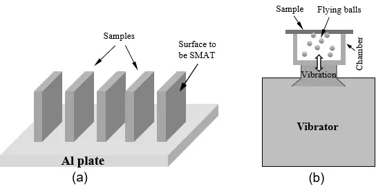
Figure 1. Schematic diagram showing (a) the SLM build orientation of the samples, and (b) the SMAT set up configuration.
A laboratory built SMAT machine was used to treat the 25 × 25 mm face built vertically by SLM (Figure 1a), with the main purpose to reduce surface roughness. The same SMAT system has previously been used to produce surface hardening of stainless steel [42] and to improve the surface finish of SLM 316L stainless steel [35]. The system consisted of a vibrator and a treatment chamber, as schematically shown in Figure 1b. During the treatment, the sample surface was bombarded repeatedly by the flying steel balls inside the chamber, due to the vibration of the chamber, which was attached to the vibrator. The repeated high speed and high frequency impacts of the surface by the steel balls could cause plastic deformation and/or fracture of the roughness peaks, resulting in surface finish improvements. SMAT process parameters include vibration frequency and amplitude, treatment time, ball material, ball size and number of balls in the chamber. These parameters affect the speed and energy of the balls impacting the sample surface, as well as the efficacy of roughness reduction. Preliminary experiments were first conducted to determine the vibration frequency, amplitude and ball size, using surface finish improvement as the criterion. Based on the initial trial experiments and previous work on SMAT of stainless steels [35,42], it was determined to use stainless steel bearing balls of 5 mm diameter, which have a surface finish of 0.06 μm and a hardness of 710 HV0.1, a vibration frequency of 30 Hz and amplitude of 7 mm. The SLM aluminum alloy surfaces were treated using the above parameters for various times from 10 min to 30 min. Before and after the treatment, the mass of the sample was measured using an analytical balance accurate to 10−3 g, and the thickness of the sample was measured using a micrometer accurate to 2 μm, which could provide information regarding material loss and surface deformation induced by SMAT. Three samples were tested under each condition, and if large differences among the three tests were observed, a fourth test was conducted. The results from these tests are presented in this manuscript to show data variations.
Before and after SMAT, the surface profiles and surface finish were measured by a contact-type stylus profilometer (Mitutoyo SJ-300, Kawasaki, Japan). The surface roughness parameters, Ra (arithmetic average) and Rz (maximum height), were acquired from 6 tests for each sample. The surface hardness of the SMAT surfaces and the as-SLM sample was measured under an indentation load of 100 g, using a Vickers microhardness tester (Sinowon, Dongguan, China). Since the as-SLM surface was too rough for microhardness measurements, it was manually ground to remove the initial surface roughness peaks, achieving a surface finish of 0.1 μm (Ra), after which microhardness measurements were performed. No further surface preparation was applied to the SMAT surfaces. Furthermore, to evaluate the subsurface hardening effect, microhardness profiles were measured across the subsurface region on the cross-sections of the SMAT samples, which were prepared by standard metallographic procedures.
An optical microscope (Olympus GX53, Tokyo, Japan) and a scanning electron microscope (SEM) (Verios 5 UC, Thermo Fisher, Brno, Czech Republic) were used to examine the surface morphology and cross sections of the samples. The optical microscope was also used to quantitatively measure the percentage of polished or contact area using the ImageJ image analysis software (Version 1.54t). For this purpose, six images were taken from each sample (three samples were analyzed under each SMAT condition) at a magnification of 50, and the ImageJ software was then used to analyze the images employing the same threshold of 85% for each image. X-ray diffraction (XRD) was used to analyze the phase compositions of the samples using Cu-Kα radiation (D8 Advance, Bruker, Karlsruhe, Germany). XRD was also used to measure the residual stresses of the SMAT surfaces based on the sin2ψ method, using the high angle lattice plane (422) (2θ~137°) and Cu-Kα radiation, following standard measurement procedures. In brief, during experimental implementation, the XRD instrument systematically tilted the sample at 0°, 10°, 30°, and 40° angles (ψ tilt angle) while the diffraction angle 2θ of the (422) lattice plane was recorded for each tilt position. After calculating the lattice spacing data (d), a linear regression fitting of the d-sin2ψ curve was performed, and from the slope of the fitted straight line, together with the known elastic modulus and Poisson’s ratio, the residual stress value on the surface was determined. In this work, residual stress measurements were only performed on the surfaces of the samples. Due to the limited X-ray penetration, only a thin layer, a few microns thick, was captured, representing surface residual stress originating from the SLM and SMAT processes.
3. Results and Discussion
A typical surface profile of the as-SLM sample is given in Figure 2a, which shows that the as-SLM surface was quite rough with peaks as high as 60 μm and valleys as deep as 60 μm, and the mean Ra was about 20 μm and Rz was about 120 μm. This indicates that in order to eliminate all the original roughness peaks and valleys, a surface layer of about 120 μm thick should be removed [28]. The roughness features of SLM surfaces are believed to result from rippling in the melt pools due to instability and surface tension, from the staircase effect, and from the partially melted or sintered powders sticking to the surface [12,30]. As can be clearly seen from Figure 2b, there were ripples, protrusions, deep valleys, and many partially melted particles on the SLM surface. In the cross-section shown in Figure 2c, there can be seen surface peaks, valleys, microcracks, and pores. Such SLM surface features have been observed and reported by many investigators [10,25,33], which may affect the surface quality, particularly the friction, wear, and fatigue properties of SLM components [35,44].
SMAT involved bombarding the rough SLM surface repeatedly with spherical and smooth steel balls of 5 mm diameter, which could cause plastic deformation and/or fracture of the roughness peaks. Thickness and mass measurements before and after SMAT revealed that the thickness of the sample was reduced continuously with increasing SMAT time, as can be seen from Figure 3. Thickness reduction was rapid at the initial stage of SMAT, then it became more gradual after 10 min (Figure 3). Interestingly, SMAT also led to a loss in the mass of the sample and such a mass loss was rapid at the initial stage of SMAT (10 min) and then it became more gradual (see Figure 3). There are obvious reasons for the observed thickness reduction and mass loss. Plastic deformation of the roughness peaks flattened the high peaks, thereby reducing thickness. Fracture of some of the asperities could also contribute to thickness reduction. However, plastic deformation is believed to play a major role due to the plasticity of the aluminum alloy [20], as confirmed by the SEM images shown in Figure 4. On the other hand, mass loss could have two origins, one being the fracture of some asperities and the other being the removal of the loosely-bonded particles which could not be completely removed by ultrasonic cleaning before SMAT.
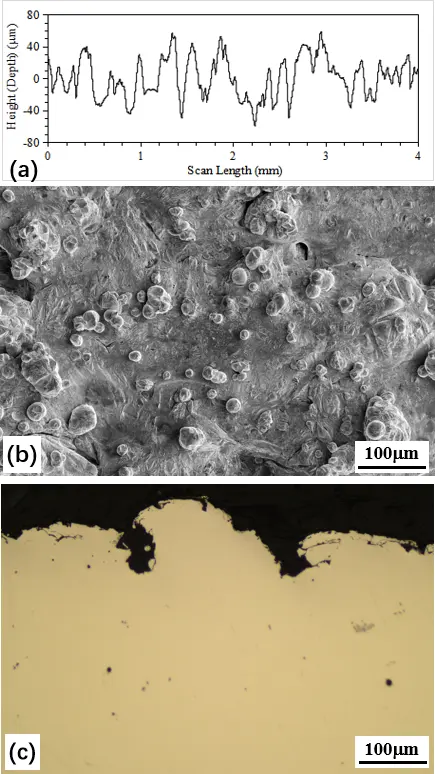
Figure 2. Surface roughness profile (a), surface morphology (b), and cross-section (c) of the as-SLM sample.
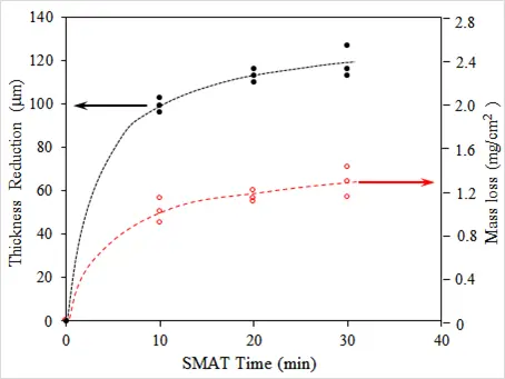
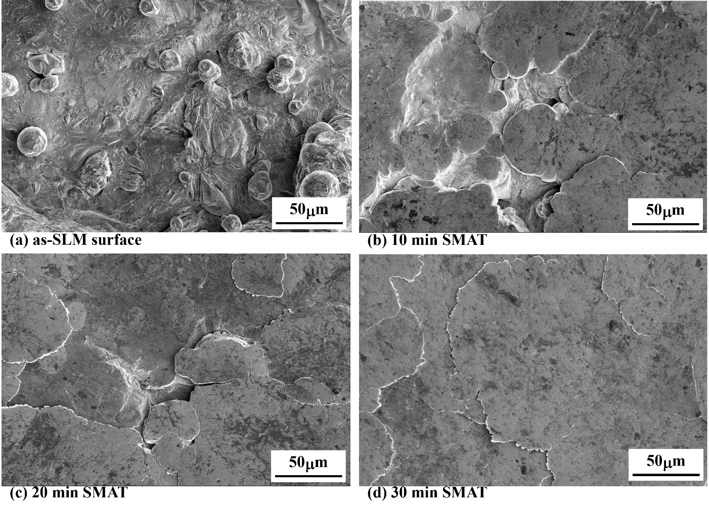
Figure 4. SEM images showing the surface morphology of the (a) as-SLM, (b) 10 min SMAT, (c) 20 min SMAT, and (d) 30 min SMAT surfaces.
Figure 4 shows typical SEM images of the sample surfaces after SMAT for various times. After 10 min of SMAT (Figure 4b), the highest peaks were deformed, and the deformed material spread into the surrounding area, forming flattened, smooth areas. It is also noted that some of the spherical particles sticking on the SLM surface were flattened due to plastic deformation, while some particles were obviously detached from the surface duo to the dynamic impacts of the balls. It is evident from Figure 4b that although the valleys on the surface could be clearly seen, there were no particles there, while there were particles in the valleys on the as-SLM surface (Figure 4a). As discussed before, the removal of the loosely-bonded particles could contribute to mass loss of the sample. With further increasing SMAT time, the SLM surface was further flattened, and the number of valleys exposed to the surface was reduced (Figure 4c,d). The SLM surface areas that made contact with the flying balls were polished and smoothed. Examined under an optical microscope, such polished or contact areas were seen as bright and shinny areas, as shown in Figure 5. Quantitative image analysis revealed that after 10 min SMAT, around 80% of the SLM surface areas were already covered by the balls, and increasing SMAT time to 20 min, the coverage area was increased to 87% (Figure 5d). Obviously, after 10 min and 20 min SMAT, the roughness peaks were deformed and the deformed materials spread to fill the surrounding valleys. This is consistent with thickness reduction measurements shown in Figure 3, which shows that after 10 min of SMAT, the thickness of the sample was reduced by nearly 100 μm. However, because the as-SLM surface had valleys as deep as 60 μm, it was difficult to achieve nearly 100% coverage without causing excessive damage to the surface. Indeed, further increasing SMAT time to 30 min only increased the coverage area to 93%, leaving behind 7% uncovered areas (valley areas) exposed to the surface.
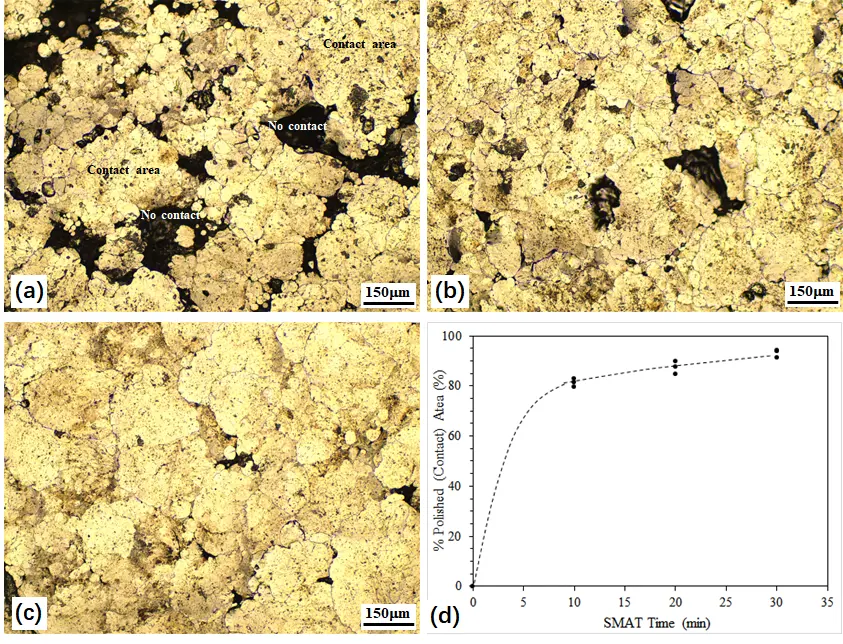
Figure 5. Optical micrographs showing polished areas of the sample surface after SMAT for (a) 10 min, (b) 20 min and (c) 30 min, and (d) percent of contact area as a function of SMAT time.
Figure 6 compares the surface profiles of the samples after SMAT for various times. It can be seen that SMAT was very effective in smoothing the SLM surfaces by flattening the original roughness peaks through asperity deformation and fracture, as well as filling the roughness valleys with deformed material. After 10 min SMAT, almost all of the roughness peaks were removed, but a significant number of valleys were still exposed to the surface (Figure 6). Increasing SMAT time to 20 min and 30 min further reduced the number of exposed valleys, leading to further smoothing of the surface. The effect of SMAT time on smoothing the SLM surface can be more clearly seen in Figure 7. SMAT for just 10 min reduced Ra from 19.4 μm to 4.5 μm and Rz from 116 μm to 37 μm, registering an improvement in surface finish by 76.8% (Ra) and 68.1% (Rz), respectively. The surface finish was further improved by increasing SMAT time: after 30 min SMAT, the surface roughness value (Ra) was further reduced to 2.6 μm (by 87%). Obviously, the reduction in surface roughness was the most effective after the first 10 min SMAT, and with increasing SMAT time, the effectiveness in improving surface finish diminished gradually, in consistent with thickness reduction and mass loss measurements shown in Figure 3. Further attempts were made to increase the SMAT time above 30 min, however, these did not lead to further reductions in Ra and Rz values, suggesting that plastic deformation of the surface asperities reached the saturation level which was limited by the ability of the present SMAT facility set up.
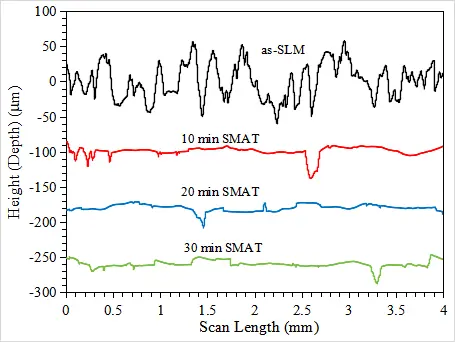
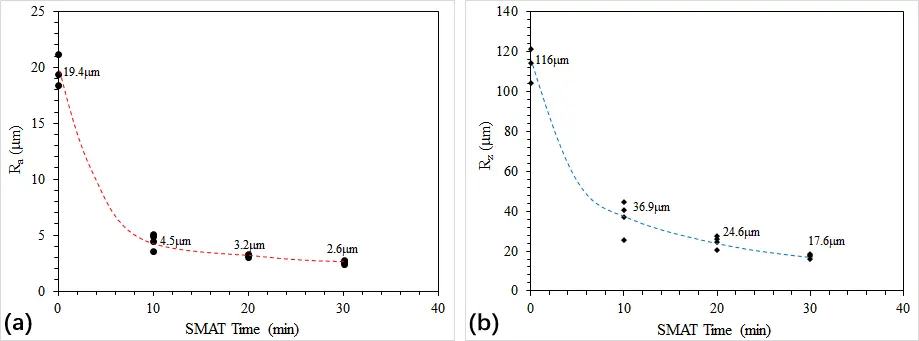
Figure 7. Surface roughness (a) Ra and (b) Rz as a function of SMAT time, showing the effectiveness of SMAT in smoothing SLM surfaces.
In order to gain a better understanding of the mechanisms of surface smoothing by SMAT, a surface profile was measured across the boundary area between the as-SLM surface and the SMAT surface, as shown in Figure 8. Clearly, the surface peaks were removed through plastic deformation (as evidenced in Figure 4) and asperity fracture (as evidenced by the mass loss shown in Figure 3). It is also clear that plastic deformation was limited to the roughness peaks and did not reach the valleys. However, most of the valleys disappeared in the SMAT area, which suggests that the deformed materials from the peaks spread over to fill the valleys, leading to further smoothing of the surface. Thus, there must be parting-lines formed between the filling materials and the surfaces of the valleys, as observed previously for SMAT of SLM 316L stainless steel [35].
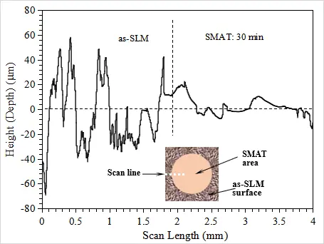
Figure 8. Surface profile measured across the boundary area between the as-SLM area and the SMAT-treated area.
Indeed, cross-sectional examination (Figure 9) revealed that after SMAT for 10 min, most of the surface peaks disappeared and some valleys could still be seen (Figure 9b). In the valley areas, there are crack-like dark lines (arrowed in Figure 9b). It is believed that these crack-like dark lines are parting-lines between the filling materials and the valley surfaces [35]. To further confirm this, an SMAT experiment was conducted on the ground surface of an SLM sample, where, before SMAT, the surface was ground to remove all the original roughness peaks and valleys to achieve a smooth surface of 0.1 μm (Ra). After SMAT for 20 min, the cross-section was examined, as shown in Figure 10. No cracks or parting-lines were observed, suggesting that the dark lines shown in Figure 9 are not cracks, but are parting-lines between the filling materials and the valley surfaces. Such a feature is more clearly seen in Figure 9c, which shows that after SMAT for 20 min, most of the valleys were filled with deformed material, forming parting lines. Some of the weakly-bonded filling material seemed to have come off the surface. Further increasing the SMAT time to 30 min could lead to further smoothing the surface through further surface deformation and increased fusion between the filling material and the valley surfaces (see Figure 9d).
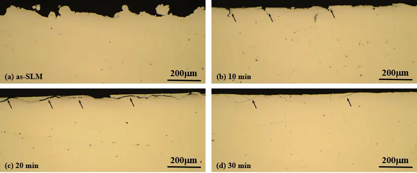
Figure 9. Cross-sectional morphology (un-etched) of the (a) as-SLM, (b) 10 min SMAT, (c) 20 min SMAT, and (d) 30 min SMAT samples. Arrows indicate parting lines between deformed material and the original surface of the valleys.
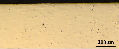
Figure 10. Cross-sectional morphology (un-etched) of the ground SLM sample after SMAT for 20 min. Before SMAT, the SLM surface was ground to remove the original peaks and valleys.
Figure 11 shows SEM images of the cross-section of the 10 min SMAT sample after etching to reveal the microstructures. Except for the near surface region, where asperity deformation and filling of the valleys with the deformed materials are obvious, no major difference in structures was observed between the as-SLM sample and the SMAT sample, both containing columnar grain regions and fine grain regions, typical of SLM aluminum alloys reported by many investigators [20,21]. Similarly, XRD analysis could not detect any major changes in the phase composition after SMAT treatment (Figure 12). The as-SLM sample contains an aluminum solid solution fcc phase. After SMAT treatment, the same phase was detected, but the diffraction peaks were broadened and shifted slightly to lower 2θ angles, as shown in Figure 12b. Peak broadening could be the result of grain refinement and microstrains in the surface region, and peak shifting could be the result of macro residual stresses on the surface [45]. The residual stresses on the SMAT surfaces were measured by XRD based on the sin2ψ method, and the results are shown in Table 2. Although the as-SLM surface exhibits a tensile residual stress of 62 MPa, compressive residual stresses ranging from −100 MPa to −118 MPa were detected on the SMAT surfaces, and as SMAT time increased, the compressive residual stress increased slightly. As reported extensively in the literature, SLM generates tensile residual stresses in the outer layers due to the large thermal gradient during the layer-by-layer manufacturing process [46,47,48]. It has been reported that the SLM AlSi10Mg alloy can have a tensile residual stress of about 70 MPa in the outer layer [48]. The SMAT treatment in the present work has not only removed the harmful tensile residual stresses but also generated compressive residual stresses on the surface, which could be beneficial for the improvement of fatigue properties of SLM aluminum alloys. Since residual stress measurements were performed only on the surfaces of the samples, the values listed in Table 2 are representative only of thin surface layers a few microns thick. To further evaluate the effect of SMAT on the fatigue properties of the samples, it is necessary to measure residual stress profiles along the depth of the samples, coupled with fatigue performance measurements. This forms the subject of our further investigation in the near future.
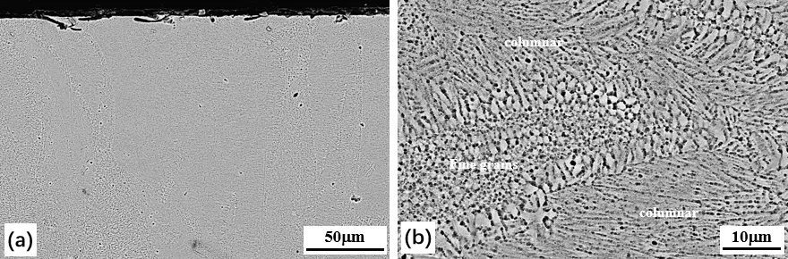
Figure 11. SEM images showing the cross-sectional structure of the 10 min SMAT specimen: (a) overall view and (b) enlarged view.
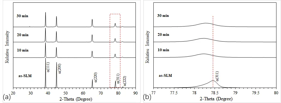
Figure 12. (a) XRD patterns from the samples and (b) zoom-in view of the α(311) peak, showing peak broadening and shift.
Table 2. Surface hardness, residual stress and roughness (Ra and Rz) after SMAT for various times.
|
SMAT Time (min) |
Surface Hardness (HV0.1) |
Residual Stress (MPa) |
Ra (μm) |
Rz (μm) |
|---|---|---|---|---|
|
0 |
124 ± 4 |
62 |
19.4 ± 1.1 |
116 ± 5.6 |
|
10 |
153 ± 10 |
−100 |
4.5 ± 0.9 |
36.9 ± 7.6 |
|
20 |
158 ± 4 |
−105 |
3.2 ± 0.2 |
24.6 ± 3.9 |
|
30 |
160 ± 5 |
−118 |
2.6 ± 0.2 |
17.6 ± 1.6 |
Compressive residual stress evolution was obviously due to plastic deformation of the surface peaks, which could also result in hardness increase in the surface region. Table 2 also lists the measured surface hardness of the samples. After SMAT, the surface hardness was increased from 124 HV to 153~160 HV, an increase of 23% to 29%, and increasing the SMAT time can marginally increase the surface hardness. The increase in surface hardness by SMAT was obviously the result of strain hardening due to asperity plastic deformation and possibly grain refinement. Furthermore, subsurface hardening was also evident after SMAT, as shown in Figure 13. The hardness profile shows that, irrespective of SMAT time, a subsurface zone around 300 μm thick was hardened with a hardness gradient, suggesting bulk plastic deformation also occurred during SMAT to reach the subsurface region. The fact that there was no difference in the hardening depth among all the SMAT samples suggests that plastic deformation was mainly concentrated on the surface peaks and the degree of bulk deformation was similar in all SMAT samples [35]. Such surface hardening effect by SMAT could help to improve the tribological properties of SLM aluminum alloy, which will be reported in a forthcoming publication.
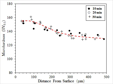
Figure 13. Hardness profiles measured across the subsurface regions of the SMAT samples, showing the hardening effect of the SMAT process.
The results presented in this section clearly show that the roughness values of Ra and Rz of the as-SLM surface can be reduced from 19.4 μm and 116 μm to 2.6 μm and 17.6 μm, respectively, after SMAT treatment for 30 min, which are improvements of 87% and 85%, respectively. SMAT also has the added benefits of increasing surface hardness, generating a strain hardened subsurface layer, and inducing compressive residual stress on the treated surface, and thus has the potential of improving mechanical properties. The SMAT technique is simple and environmentally friendly because it does not require additional heating and the use of chemicals. However, SMAT is limited by line-of-sight and can only apply to external surfaces with relatively simple geometries, such as planar surfaces and non-planar surfaces with symmetric shapes. It is difficult to apply SMAT to internal surfaces and components with complex geometries. Such technical limitations are similar to those of laser polishing, which has been employed by other investigators to polish as-built aluminum alloys. It has been reported by Zhang et al. [39] that laser polishing could reduce surface roughness (Sa) of SLM fabricated AlSi10Mg alloy by 80%, from 16 μm to 3.3 μm, while Schanz et al. [49] reported a reduction of surface roughness of SLM fabricated AlSi10Mg by 92% using a disk laser with a maximum power of 4 kW in laser polishing. As compared with laser polishing, SMAT has similar roughness reduction efficacy and the benefit of generating compressive residual stress at the surface, while laser polishing has the danger of inducing harmful tensile residual stress at the surface due to the rapid heating and cooling involved. Electropolishing (EP) is another technique that has been employed to reduce the surface roughness of as-built SLM AlSi10Mg [50]. It has been reported that EP under optimized conditions can achieve a surface roughness (Ra) < 1 μm, which is better than what can be achieved by SMAT of this work. EP can also apply to more complex components and possibly to internal surfaces with proper electrode design. However, EP normally requires some pre-treatments to remove the semi-melted particles, and the use of hazardous chemicals in the polishing electrolyte, which are mostly environmentally harmful. EP does not generate a hardened layer and compressive residual stress on the surface. Thus, the SMAT technique possesses some advantages over other post process polishing techniques for SLM fabricated aluminum alloys.
4. Conclusions
Based on the experimental results of this work, several conclusions can be drawn regarding the effectiveness of SMAT in improving the surface quality of the SLM aluminum alloy, as follows.
- (1)
-
SMAT is an effective technique to improve the surface quality of the SLM aluminum alloy, by smoothing its surface and enhancing its surface hardness.
- (2)
-
The surface roughness can be reduced by 77% (Ra from 19.4 μm to 4.5 μm) after 10 min SMAT. Increasing SMAT time to 30 min is effective in further reducing surface roughness by 87%, such that Ra is reduced to 2.6 μm and Rz is reduced to 17.6 μm.
- (3)
-
Plastic deformation and fracture of surface asperities and peaks, as well as filling of the roughness valleys by the deformed materials, are responsible for the smoothing of the SLM surface. This also results in the formation of crack-like parting lines in the near surface region.
- (4)
-
SMAT increases the surface hardness and generates a strain-hardened zone of 300 μm thick in the subsurface layer of the SLM aluminum alloy. The surface hardness is increased from 125 HV0.1 to 160 HV0.1 after 30 min SMAT treatment.
- (5)
-
SMAT removes the tensile residual stress on the as-built SLM surface and generates compressive residual stresses of 100~118 MPa on the surface. The value of compressive residual stress increases slightly with increasing SMAT time.
Acknowledgments
The authors acknowledge Jihua Laboratory for providing all the necessary resources for this research.
Author Contributions
Conceptualization, Y.S. and Y.B.; Methodology, Y.S. and Y.B.; Validation, C.Z. and H.T., Formal Analysis, Y.S., C.Z. and H.T.; Investigation, C.Z. and H.T.; Resources, Y.B. and Y.S.; Data Curation, C.Z. and H.T.; Writing—Original Draft Preparation, Y.S.; Writing—Review & Editing, C.Z. and Y.B.; Supervision, Y.B.; Project Administration, C.Z.; Funding Acquisition, Y.S. All authors have read and agreed to the published version of the manuscript.
Ethics Statement
Not applicable.
Informed Consent Statement
Not applicable.
Data Availability Statement
The original data of this work is available from the corresponding author upon reasonable request.
Funding
This work was supported by the Jihua Laboratory Program X252771TM250, the NSFC Program X2608911M260 and the Guangdong Provincial Program X2608911M26P.
Declaration of Competing Interest
The authors declare that they have no known competing financial interests or personal relationships that could have appeared to influence the work reported in this paper.
References
-
Radhika C, Shanmugam R, Ramoni M, Gnanavel BK. A review on additive manufacturing for aerospace application. Mater. Res. Expr. 2024, 11, 022001. DOI:10.1088/2053-1591/ad21ad [Google Scholar]
-
Segonds F. Design by additive manufacturing: An application in aeronautics and defence. Virtual Phys. Prototy 2018, 13, 237–245. DOI:10.1080/17452759.2018.1498660 [Google Scholar]
-
Rouway M, Tarfaoui M, Chakhchaoui N, Omari LEH, Fraija F, Cherkaoui O. Additive manufacturing and composite materials for marine energy: Case of tidal turbine. 3D Print. Addit. Manuf. 2023, 10, 1309–1319. DOI:10.1089/3dp.2021.0194 [Google Scholar]
-
Davim JP. (Ed.) Laser in Manufacturing; Wiley: Hoboken, NJ, USA, 2012. ISBN: 978-1-848-21369-2. [Google Scholar]
-
Mahmood MR, Chioibasu D, Rehman AU, Mibai S, Popescu AC. Post-processing techniques to enhance the quality of metallic parts produced by additive manufacturing. Metals 2022, 12, 77. DOI:10.3390/met12010077 [Google Scholar]
-
Wang H, Lee YL, Bai Y, Zhang J. (Eds). Post-Processing Techniques for Metal-Based Additive Manufacturing; Taylor & Fracncis, CRC Press: London, UK, 2024; pp. 29–52. [Google Scholar]
-
Vayre B, Vignat F, Villeneuve F. Metallic additive manufacturing: State-of-the-art review and prospects. Mech. Ind. 2012, 13, 80–96. DOI:10.1051/meca/2012003 [Google Scholar]
-
Brinksmeier E, Levy G, Mayer D, Spierings AB. Surface integrity of selective laser melted components. CIRP Ann. Manuf. Technol. 2010, 149, 601–606. DOI:10.1016/j.cirp.2010.03.131 [Google Scholar]
-
Chen Z, Wu X, Tomus D, Davis CHJ. Surface roughness of selective laser melted Ti-6Al-4V alloy components. Add. Manuf. 2018, 21, 91–103. DOI:10.1016/j.addma.2018.02.009 [Google Scholar]
-
Kuntoglu M, Salur E, Canli E, Aslan A, Gupta MK, Waqar S, et al. A state of the art on surface morphology of selective laser melted metallic alloys. Int. J. Adv. Manuf. Technol. 2023, 127, 1103–1142. DOI:10.1007/s00170-023-11534-7 [Google Scholar]
-
Mohammadian N, Turenne S, Brailovski V. Surface finish control of additively manufactured Inconel 625 components using combined chemical abrasive flow polishing. J. Mater. Process. Technol. 2018, 252, 728–738. DOI:10.1016/j.jmatprotec.2017.10.020 [Google Scholar]
-
Alrbaey K, Wimpenny D, Rosi R, Manning W, Moroz A. On optimization of surface roughness of selective laser melted stainless steel parts: A statistical study. J. Mater. Eng. Perform. 2014, 23, 2139–2148. DOI:10.1007/s11665-014-0993-9 [Google Scholar]
-
Tian Y, Gora WS, Cabo AP, Parimi LL, Hand DP, Tammas-Williams S, et al. Materials interaction in laser polishing powder bed additive manufactured Ti6Al4V components. Add. Manuf. 2018, 20, 11–22. DOI:10.1016/j.addma.2017.12.010 [Google Scholar]
-
Petropoulos G, Pandazaras C, Davim J. Surface texture characterization and evaluation related to machining. In Surface Integrity in Machining; Davin J, Ed.; Springer: London, UK, 2010. DOI:10.1007/978-1-84882-874-2_2 [Google Scholar]
-
Read N, Wang W, Essa K, Attallah MM. Selective laser melting of AlSi10Mg alloy: Process optimisation and mechanical properties development. Mater. Des. 2015, 65, 417–424. DOI:10.1016/j.matdes.2014.09.044 [Google Scholar]
-
Niu N, Singh S, Garg A, Singh H, Panda B, Peng X, et al. Review of materials used in laser-aided additive manufacturing processes to produce metallic parts. Front. Mech. Eng. 2019, 14, 282–298. DOI:10.1007/s11465-019-0526-1 [Google Scholar]
-
Xue L, Liao C, Wu M, Li Q, Hu Z, Yang Y, et al. Improvement of mechanical properties and corrosion resistance of SLM-AlSi10Mg alloy by an eco-friendly electric pulse treatment. J. Clean. Prod. 2024, 439, 140864. DOI:10.1016/j.jclepro.2024.140864 [Google Scholar]
-
Masood H, Ruan D, Palanisamy S. Mechanical properties of SLM-printed aluminum alloys: A review. Materials 2020, 13, 4301. DOI:10.3390/ma13194301 [Google Scholar]
-
Dasari J, Xavior MA. Review of additive manufacturing and post processing techniques for aluminum alloys with focus on microstructure changes mechanical performance and emerging trends. Discov. Mech. Eng. 2026, 5, 48. DOI:10.1007/s44245-026-00189-9 [Google Scholar]
-
Tang H, Gao C, Zhang Y, Zhang N, Lei C, Bi Y, et al. Effects of direct aging treatment of microstructure, mechanical properties and residual stress of selective laser melted AlSi10Mg alloy. J. Mate Sci. Technol. 2023, 139, 198–209. DOI:10.1016/j.jmst.2022.08.032 [Google Scholar]
-
Michi RA, Plotkowski A, Shyam A, Dehoff RR, Babu SS. Towards high temperature applications of aluminum alloys enabled by additive manufacturing. Int. Mater. Rev. 2021, 67, 1–48. DOI:10.1080/09506608.2021.1951580 [Google Scholar]
-
Tang H, Gao C, Zhang S, Xiong X, Cao S, Wu X, et al. Multivariate relationships between microstructure evolution and strengthening mechanisms in laser powder bed fusion of Al-Mn-Sc alloy: towards improved fatigue performance. Light Adv. Manuf. 2024, 5, 1. DOI:10.37188/lam.2024.001 [Google Scholar]
-
Boban J, Ahmed A, Gokcekaya O, Nakano T. Ultra-precision surface treatment of beta-titanium alloy printed using laser and electron beam melting sources. CIRP J. Manuf. Sci. Technol. 2025, 58, 1–19. DOI:10.1016/j.cirpj.2025.01.006 [Google Scholar]
-
Ma CP, Guan YC, Zhou W. Laser polishing of additive manufactured Ti alloys. Opt. Lasers Eng. 2017, 93, 171–177. DOI:10.1016/j.optlaseng.2017.02.005 [Google Scholar]
-
Bhaduri D, Ghara T, Penchev P, Paul S, Pruncu CI, Dimov S, et al. Pulsed laser polishing of selective laser melted aluminum alloy parts. App. Surf. Sci. 2021, 558, 149887. DOI:10.1016/j.apsusc.2021.149887 [Google Scholar]
-
Alfieri V, Argenio P, Gaiazzo F, Sergi V. Reduction of surface roughness by means of laser processing over additive manufacturing metal parts. Materials 2017, 10, 30. DOI:10.3390/ma10010030 [Google Scholar]
-
Zhao D, Li X. Chemical mechanical polishing: Theory ad experiment. Friction 2013, 1, 306–326. DOI:10.1007/s40544-013-0035-x [Google Scholar]
-
Gunnerek R, Soundarapandiyan G, Mishurova T, Schroder J, Bruno G, Boykin J, et al. Chemical mechanical polishing of powder bed fusion-laser beam processed 316L stainless steel. J. Mater. Process Technol. 2025, 345, 119055. DOI:10.1016/j.jmatprotec.2025.119055 [Google Scholar]
-
Acquesta A, Monetta T. The electropolishing of additively manufactured parts in titanium: State of the art. Adv. Eng. Mater. 2021, 23, 2100545. DOI:10.1002/adem.202100545 [Google Scholar]
-
Urlea V, Brailovski V. Electropolishing and electropolishing-related allowances for powder bed selectively laser-melted Ti-6Al-4V alloy components. J. Mater. Process Technol. 2017, 242, 1–11. DOI:10.1016/j.jmatprotec.2016.11.014 [Google Scholar]
-
Valentincic J, Koroth JE, Zeidler H. Advances in surface finish for additive manufacturing of metal parts: A comprehensive review of plasma electrolytic polishing (PEP). Virtual Phys. Prototy 2024, 19, e2364222. DOI:10.1080/17452759.2024.2364222 [Google Scholar]
-
Yang L, Laugel N, Housden J, Espitalier L, Matthews A, Yerokhin A. Plasma additive layer manufacture smoothing (PALMS) technology—An industrial prototype development and a comparative study on both additive manufactured and conventional machined AISI316 stainless steel. Add. Manuf. 2020, 34, 101204. DOI:10.1016/j.addma.2020.101204 [Google Scholar]
-
Bai Y, Zhao C, Yang J, Fuh JYH, Weng C, Wang H. Dry mechanical-electrochemical polishing of selective laser melted 316L stainless steel. Mater. Des. 2020, 193, 108840. DOI:10.1016/j.matdes.2020.108840 [Google Scholar]
-
Dixit N, Sharma V, Kumar P. Research trends in abrasive flow machining: A systematic review. J. Manuf. Proc. 2021, 64, 1434–1461. DOI:10.1016/j.jmapro.2021.03.009 [Google Scholar]
-
Sun Y, Bailey R, Moroz A. Surface finish and properties enhancement of selective laser melted 316L stainless steel by surface mechanical attrition treatment. Surf. Coat. Tech. 2019, 378, 124993. DOI:10.1016/j.surfcoat.2019.124993 [Google Scholar]
-
Partella Q, Chemkhi M, Retraint D. Influence of surface mechanical attrition treatment (SMAT) post-treatment on microstructure, mechanical and tensile behaviour of additive manufactured ALSI 316. Mater. Charact. 2020, 167, 110463. DOI:10.1016/j.matchar.2020.110463 [Google Scholar]
-
Sausto F, Tezzele C, Beretta S. Analysis of fatigue strength of L-PBF AlSi10Mg with different surface post-processes: Effect of residual stresses. Metals 2022, 12, 898. DOI:10.3390/met12060898 [Google Scholar]
-
Joshy J, George A, Kuriachen B, Mathew J. Influence of post processing on the micro-machining of selective laser melted AISI AlSi10Mg: An experimental investigation. Mater. Manuf. Process 2023, 38, 516–528. DOI:10.1080/10426914.2022.2075886 [Google Scholar]
-
Zhang D, Yu J, Li H, Zhou X, Song C, Zhang C, et al. Investigation of laser polishing of four selective laser melting alloy samples. Appl. Sci. 2020, 10, 760. DOI:10.3390/app10030760 [Google Scholar]
-
Liu ZG, Fecht HJ, Umemoto M. Microstructural evolution and nanocrystal formation during deformation of Fe-C alloys. Mater. Sci. Eng. 2004, A375, 839–843. DOI:10.1016/j.msea.2003.10.136 [Google Scholar]
-
Lu K, Lu J. Nanostructured surface layer on metallic materials induced by surface mechanical attrition treatment. Mater. Sci. Eng. 2004, A375–377, 38–45. DOI:10.1016/j.msea.2003.10.261 [Google Scholar]
-
Sun Y. Sliding wear behaviour of surface mechanical attrition treated AISI 304 stainless steel. Tribol. Int. 2013, 57, 67–75. DOI:10.1016/j.triboint.2012.07.015 [Google Scholar]
-
Roland T, Retraint D, Lu K, Lu J. Fatigue life improvement through surface nanostructuring of stainless steel by means of surface mechanical attrition treatment. Scr. Mater. 2006, 54, 1949–1954. DOI:10.1016/j.scriptamat.2006.01.049 [Google Scholar]
-
Maleki E, Bagherifard S, Bandini M, Guagliano M. Surface post-treatments for metal additive manufacturing: Progress, challenges, and opportunities. Add. Manuf. 2021, 37, 101619. DOI:10.1016/j.addma.2020.101619 [Google Scholar]
-
Gangwar K, Ramulu M. Residual stress measurement using X-ray diffraction in friction stir-welded dissimilar titanium alloys. Materials 2024, 17, 1482. DOI:10.3390/ma17071482 [Google Scholar]
-
Beretta S, Gargourimotlagh Foletti MS, Plessis AD, Riccio M. Fatigue strength assessment of ‘as build’ AlSi10Mg manufactured by SLM with different build orientations. Int. J. Fatigue 2020, 139, 105737. DOI:10.1016/j.ijfatigue.2020.105737 [Google Scholar]
-
Beretta S, Patriarca L, Gargourimotlagh M, Hardaker A, Bracket D, Salimian M, et al. A benchmark activity on the fatigue life assessment of AlSi10Mg components manifactured by L-PBF. Mater. Des. 2021, 218, 110713. DOI:10.1016/j.matdes.2022.110713 [Google Scholar]
-
Sausto F, Carrion P, Shamsaei N, Beretta S. Fatigue failure mechanisms for AlSi10Mg manufactured by L-PBF under axial and torsional loads: The role of defects and residual stresses. Int. J. Fatigue 2022, 162, 106903. DOI:10.1016/j.ijfatigue.2022.106903 [Google Scholar]
-
Schanz J, Hofele M, Hitzler L, Merkel M, Riegel H. Laser polishing of additive manufactured AlSi10Mg parts with an oscillating laser beam. In Machining, Joining and Modifications of Advanced Materials; Advanced Structured Materials; Ochsner A, Altenbach H, Eds.; Springer: Singapore, 2016; Volume 61. DOI:10.1007/978-981-10-1082-8_16 [Google Scholar]
-
Jeong JU, Lee KK, Ahn DG, Jeong WL. Study of surface roughness change of AlSi10Mg based on selectrive laser melting (SLM) using electro-polishing technique. J. Mech. Sci. Technol. 2024, 38, 4579–4585. DOI:10.1007/s12206-024-2412-y [Google Scholar]