
Microstructure, Mechanical and Ablation Properties of Csf Reinforced C-ZrC-CuNi Composites
Microstructure, Mechanical and Ablation Properties of Csf Reinforced C-ZrC-CuNi Composites
Haibo Ouyang * Yumiao Xing Cuiyan Li * Siyi Qi Tianzhan Shen Yanlei Li Xiaoyue Sun Shuai Zhang Xinnuo Wang Xilin Wang Xinge Niu
Received: 17 July 2026 Revised: 10 August 2026 Accepted: 27 August 2026 Published: 09 September 2026

© 2026 The authors. This is an open access article under the Creative Commons Attribution 4.0 International License (https://creativecommons.org/licenses/by/4.0/).
1. Introduction
With the rapid development of hypersonic aircraft and reusable launch vehicles in the aerospace industry, thermal structural components are subjected to coupled extreme service conditions, including ultra-high temperature, aerobic oxidation, high-velocity gas erosion, and alternating thermal shock, which impose stringent requirements on the comprehensive performance of thermal protection materials [1,2,3,4,5,6,7,8]. Carbon-based ultra-high temperature ceramic composites stand out as core candidate materials for flight vehicle thermal protection systems due to their low density, superior high-temperature mechanical properties, and excellent thermal shock resistance [9,10,11,12,13,14,15]. Among them, ZrC-based composites possess a high melting point and excellent high-temperature chemical stability [16,17,18,19,20]. A dense ZrO2 layer with a high melting point can form on their surface in aerobic environments, acting as a physical barrier that resists erosion by flame and oxygen. Thus, they are one of the most widely used ultra-high temperature ceramic systems [21,22,23,24,25,26,27,28].
To further boost the heat dissipation capacity of ZrC composites, researchers introduced low-melting-point CuNi alloys [29,30,31,32,33]. The solid-liquid-gas phase transition of CuNi produces the transpiration cooling effect, which removes massive heat and realizes a synergistic thermal protection system combining active metal heat dissipation and passive ceramic barrier [34,35,36,37,38,39,40,41,42]. Wang et al. [43] prepared C/C-SiC-ZrC composites by a two-step reactive melt infiltration (RMI) method using Si/Zr and Cu/Ti precursors. Their results indicated that the active heat dissipation of Cu significantly reduced the thermal response temperature of composite surfaces during ablation, and the generated Si-Ti-Zr-O layer acted as an effective barrier to protect the substrate. Yang et al. [44] fabricated C/C-ZrC-ZrxCuγ composites via pressure-assisted reactive melt infiltration. Their ablation tests revealed that the endothermic effect of Cu slowed the rise in surface temperature during the first 30 s of ablation. After 60 s of ablation, the initially porous ZrO2 skeleton transformed into an integrated, continuous protective layer, greatly enhancing the ablation resistance of materials. The CuNi alloy can optimize both the matrix thermal conductivity and the densification of the oxide layer in C-ZrC-CuNi composite materials. Nevertheless, obvious mismatches in thermal expansion coefficients between the ZrC ceramic and CuNi metal phases lead to concentrated thermal stress inside composites under drastic temperature cycling and ablation conditions, triggering surface cracking and oxide film spalling. The integrity of the protective system is destroyed, which drastically shortens the service life and becomes a critical bottleneck restricting the engineering application of this composite system.
Sha et al. [45] took fiber-free ZrB2-ZrSi2 ceramics as the control group and studied the toughening effect of short carbon fiber in ZrB2-ZrSi2 composites. The short carbon fibers were uniformly distributed in the matrix, and the relative density of the composites reached 97.92%. Multiple energy-absorbing mechanisms, including fiber bridging, fiber-matrix debonding, and fiber pull-out, jointly consumed fracture energy and greatly elevated the fracture toughness of ceramics. Zhang et al. [46] fabricated dense Cf/SiC composites with 0.5 mm short carbon fiber as the reinforcement. The test results demonstrated that adding 8 wt.% carbon fiber increased the fracture toughness by 33.33%, and the corresponding toughening mechanisms, such as fiber pull-out, interfacial debonding, and crack deflection, were elaborated based on experimental observations.
On the basis of the above research, Csf/C-ZrC-CuNi composites with varying short carbon fiber mass fractions were prepared by hydrothermal method, tube furnace sintering, and spark plasma sintering (SPS). Combined with X-ray Diffraction (XRD), Scanning Electron Microscopy (SEM), Energy-Dispersive X-ray Spectroscopy (EDS), mechanical tests, and oxyacetylene ablation experiments, the effects of carbon fiber dosage on phase composition, micromorphology, mechanical performance, and high-temperature ablation behavior of composites were systematically investigated. Thermodynamic analysis was further adopted to reveal the synergistic interaction mechanism among short carbon fiber, CuNi alloy, and ZrC ceramic.
2. Materials and Methods
2.1. Experimental Raw Materials
For this study, polyacrylonitrile (PAN)-based long-fiber chopped strand (supplied by Guangdong Dongli Carbon Fiber Co., Ltd., Shenzhen, China) was used as the reinforcement material; a 2.5D needle-punched carbon felt (supplied by Jiangsu Tianniao High-Tech Co., Ltd., Yixing, China, model 12K T700SC, with a tensile strength of 4.9 GPa, a tensile modulus of 230 GPa, and a density of approximately 0.8 g/cm3) was employed as the carbon fiber preform. The carbon fiber preform was then machined into cylindrical specimens measuring Φ30 mm × 10 mm.
The experimental raw materials used in this paper are listed in Table 1.
Table 1. Raw materials used in the experiments.
|
Name |
Molecular Formula |
Purity Grade |
Manufacturer |
|---|---|---|---|
|
Glucose |
C6H12O6 |
AR |
Sinopharm Collective Chemical Reagents Co., Ltd. |
|
Nickel nitrate hexahydrate |
Ni(NO3)2·6H2O |
AR |
Aladdin |
|
Copper sulfate pentahydrate |
CuSO4·5H2O |
AR |
Sinopharm Collective Chemical Reagents Co., Ltd. |
|
Urea |
CH4N2O |
AR |
Sinopharm Collective Chemical Reagents Co., Ltd. |
|
Zirconium carbide |
ZrC |
≥99.99% |
Aladdin |
|
Zirconium chloride |
ZrCl4 |
AR |
Aladdin |
|
Furfuryl alcohol |
C5H6O2 |
98% |
Sinopharm Collective Chemical Reagents Co., Ltd. |
|
Absolute ethyl alcohol |
C2H6O |
99.5% |
Sinopharm Collective Chemical Reagents Co., Ltd. |
2.2. Fabrication of Csf/C-ZrC-CuNi Composites
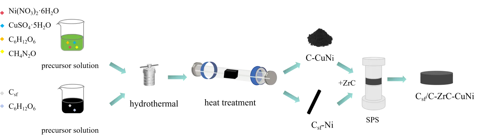
The Csf/C-ZrC-CuNi composites were synthesized via SPS, and the detailed fabrication flowchart is shown in Figure 1. The specific procedures are described as follows:
- (1)
-
Preparation of C-CuNi powders: Glucose, nickel nitrate hexahydrate, copper sulfate pentahydrate, and urea were mixed and stirred to obtain a precursor solution with a Ni/Cu molar ratio of 0.6. The precursor underwent a hydrothermal reaction at 200 °C for 6 h, followed by solid-liquid separation, washing, and drying to gain oxide precursors. The obtained powders were calcined at 1000 °C for 2 h under an argon atmosphere to synthesize C-CuNi powders via carbothermal reduction.
- (2)
-
Fabrication of Ni-coated short carbon fibers: Pyrolytic carbon (PyC) coating was first deposited on carbon fibers by a hydrothermal method. A certain amount of glucose and short carbon fibers were dissolved in deionized water and fully stirred. The mixed solution was transferred into a hydrothermal reactor and reacted at 200 °C for 6 h. After repeated filtration, washing, and drying at 80 °C, the samples were heat-treated at 800 °C for 2 h under Ar atmosphere to obtain PyC-coated carbon fibers. Subsequently, a Ni coating was deposited on the PyC-modified carbon fibers via another hydrothermal route. Nickel nitrate hexahydrate and urea were dissolved in deionized water with carbon fibers, followed by sufficient stirring. Urea acted as a mineralizer to create an alkaline hydrothermal environment. The mixture was subjected to hydrothermal treatment at 200 °C for 2 h. After filtration, washing, and drying, the powders were annealed at 600 °C for 2 h in Ar to produce Ni-coated short carbon fibers (Csf-Ni).
- (3)
-
Sintering of Csf/C-ZrC-CuNi composites: Weigh 4.2 g of C-CuNi powder, a certain mass of ZrC powder, and short-cut carbon fibers coated with Ni onto a mixture in an ethanol solution; the total mass of the powders is 14 g, while the mass fractions of short carbon fibers were set as 5 wt.%, 10 wt.%, 15 wt.%, and 20 wt.%, respectively. The suspension was heated and stirred to evaporate ethanol and acquire uniform mixed powders. The mixtures were filled into graphite dies with a diameter of 30 mm, and spark plasma sintering was carried out at 1200 °C under a uniaxial pressure of 40 MPa with a holding time of 10 min to prepare the target Csf/C-ZrC-CuNi composites. The SPS sintering process was performed under a vacuum atmosphere, and the chamber pressure was maintained below 10 Pa during the whole sintering procedure.
2.3. Characterization and Testing
An X-ray diffractometer (D/max2200PC, Rigaku, Tokyo, Japan) was used to characterize the phase compositions of raw powders and ablated samples. The micromorphology of precursors, bulk composites, and post-ablation specimens was observed by Hitachi S-4800 and S-8100 field emission scanning electron microscopes (FE-SEM,Hitachi High-Tech Corporation, Tokyo, Japan), equipped with energy dispersive X-ray spectroscopy (EDS) for elemental composition analysis.
Three-point bending tests were performed to measure flexural strength. Specimen dimensions were 25 × 10 × 2.5 mm3 with a span of 20 mm and a crosshead speed of 0.5 mm/min. Three parallel samples were tested for each group, and the average value was adopted. The flexural strength formula is as follows:
|
```latex\text{σ}\text{ }\text{=}\text{ }\frac{\text{3FL}}{\text{2b}{\text{h}}^{\text{2}}}``` |
(1) |
where:
σ—flexural strength (MPa);
F—maximum fracture load (N);
L—support span (mm);
b—specimen width (mm);
h—specimen thickness (mm).
The ablation resistance of the composite material was evaluated using an oxyacetylene flame. In accordance with the GJB323A-96 standard [47], an ablation test was conducted using an oxyacetylene flame with a thermal flux of 2.38 MW/m2; the sample was machined into a cylindrical shape measuring Φ30 × 10 mm. The relevant parameters were as follows: O2 flow rate—0.42 L/s, gas pressure—0.4 MPa; C2H2 flow rate—0.18 L/s, gas pressure—0.095 MPa; the distance between the ablation gun nozzle and the sample surface was 10 mm. The ablation surface temperature was measured using an infrared thermometer during the ablation process. The sample was ablated and then cooled within the oxyacetylene flame for a duration of 60 s. Oxyacetylene flame ablation experiments were carried out to evaluate the ablation resistance of composites. The mass ablation rate (Rm) and linear ablation rate (Rl) were calculated according to the mass and thickness changes before and after ablation:
|
```latex{\text{R}}_{\text{m}}\text{ }\text{=}\text{ }\frac{{\text{m}}_{\text{0}}\text{ }-\text{ }{\text{m}}_{\text{t}}}{\text{t}}``` |
(2) |
|
```latex{\text{R}}_{\text{l}}\text{ }\text{=}\text{ }\frac{{\text{l}}_{\text{0}}\text{ }-\text{ }{\text{l}}_{\text{t}}}{\text{t}}``` |
(3) |
where:
m0—mass of sample before ablation (g);
mt—mass of sample after ablation (g);
l0—thickness of sample before ablation (mm);
lt—thickness of sample after ablation (mm);
t—total ablation time (s).
3. Results and Discussion
3.1. Phase Composition and Microstructure of C/CuO-NiO Powders
Figure 2a shows the XRD pattern of C/CuO-NiO powders prepared via hydrothermal reaction at 200 °C. The hydrothermal powders mainly consist of C, CuO, and NiO phases, with sharp diffraction peaks of CuO and NiO, indicating high crystallinity of the two metal oxides. Figure 2b,c display SEM images of C/CuO-NiO powders at different magnifications. Smooth grey carbon spheres with an agglomerated state can be clearly observed, and small spherical particles with a diameter of 1–3 μm are attached to the carbon sphere surface. Combined with XRD analysis, these granular substances are identified as CuO-NiO particles. Nano-sized CuO-NiO particles are uniformly loaded on carbon spheres, proving that the hydrothermal method achieves uniform loading of metal oxides. In addition, the addition of Ni effectively improves the wettability between C and Cu and strengthens the interfacial bonding force between them.
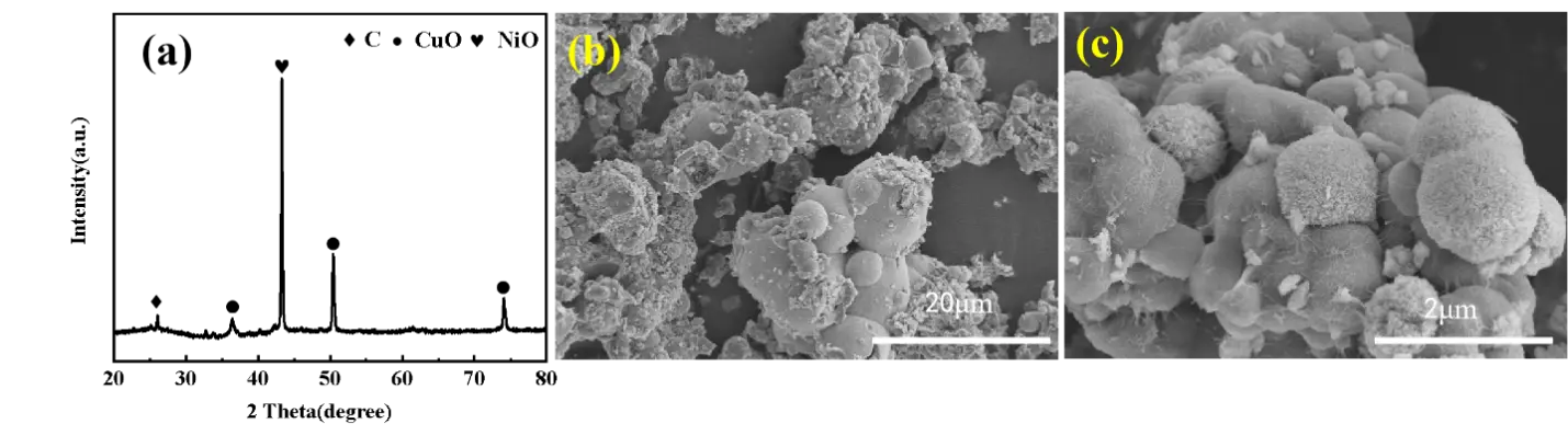
Figure 2. (a) XRD pattern of C/CuO-NiO powders; (b,c) SEM images of C/CuO-NiO powders at different magnifications.
3.2. Phase Composition and Microstructure of C-CuNi Powders
After carbothermal reduction of C/CuO-NiO powders at 1000 °C, C-CuNi composite powders were successfully obtained. Figure 3a presents the XRD pattern of C-CuNi powders, where the characteristic diffraction peaks at 43.6°, 50.79°, and 74.67° correspond to the (111), (200) and (220) crystal planes of CuNi alloy (PDF#47-1406). Cu and Ni have similar atomic radii (128 pm and 124 pm, respectively) and both adopt face-centered cubic crystal structures, satisfying the Hume-Rothery rule for forming unlimited solid solutions. Sufficient atomic diffusion at high temperature promotes the formation of homogeneous Cu-Ni alloy solid solutions, and no residual diffraction peaks from CuO or NiO are detected, thereby verifying the complete carbothermal reduction reaction at this temperature.
Figure 3b,c show the micromorphology of C-CuNi powders. Spherical CuNi alloy particles with a diameter of 0.5–1 μm are uniformly distributed on the surface of carbon spheres without obvious agglomeration or sintering necks. The carbon matrix limits the excessive growth of CuNi grains during high-temperature reduction. Clear, gap-free interfaces exist between CuNi particles and the carbon substrate, demonstrating excellent wettability and strong interfacial bonding. During carbothermal reduction, carbon acts as a reducing agent, and the three-dimensional network of carbon spheres provides a supporting medium for the uniform dispersion of CuNi alloy particles.
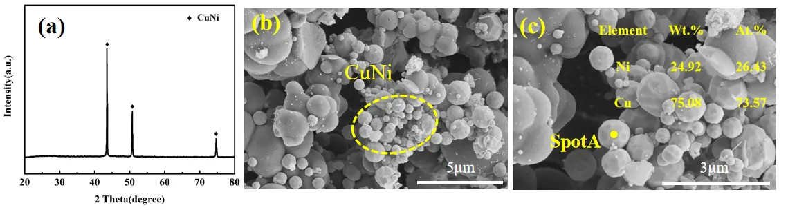
Figure 3. (a) XRD pattern of C-CuNi powders; (b,c) SEM images of C-CuNi powders at different magnifications.
3.3. Phase Composition and Microstructure of Csf-Ni
Figure 4a,b are SEM images of carbon fibers coated with pyrolytic carbon (PyC) prepared by hydrothermal treatment. A uniform PyC coating with a thickness of approximately 500 nm tightly covers the fiber surface. The PyC coating surface exhibits a typical granular structure with a uniform particle size distribution and no significant agglomeration phenomenon, and the interface between the coating and carbon fiber is compact and crack-free. The original fibrous morphology remains intact after hydrothermal treatment, confirming that the mild preparation process does not damage the carbon fiber substrate. The PyC protective layer can prevent fiber corrosion and oxidation during subsequent high-temperature sintering and optimize the interfacial compatibility between fibers and the matrix.
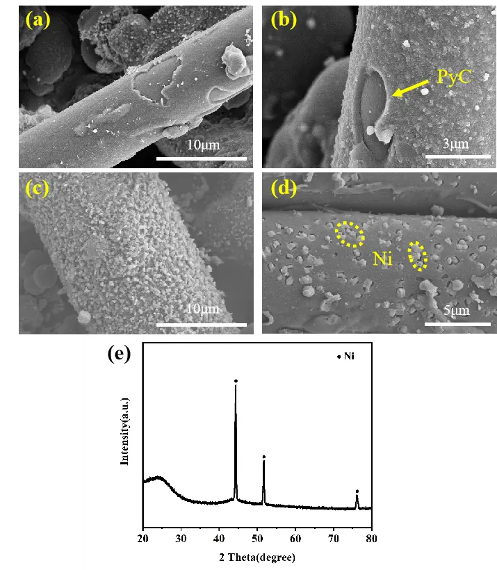
Figure 4. (a,b) SEM images of PyC-coated carbon fibers; (c,d) SEM images of Ni-coated short carbon fibers; (e) XRD pattern of Ni-coated short carbon fibers.
Figure 4c,d illustrate the micromorphology of Ni-modified short carbon fibers (Csf-Ni). Uniform Ni particles with an average size of ~1 μm are deposited on the fiber surface. In a hydrothermal system with urea as mineralizer, Ni(OH)2 precipitates and accumulates on carbon fibers; subsequent heat treatment at 600 °C under an Ar atmosphere reduces the hydroxide to metallic Ni. Partial Ni particles embed into the fiber surface due to favorable carbon-nickel wettability, forming strong mechanical interlocking and enhancing the fiber-matrix interfacial bonding strength.
Figure 4e shows the XRD pattern of Csf-Ni. Sharp diffraction peaks located at 43.49°, 51.84°, and 76.38° match the (111), (200), and (220) crystal planes of metallic Ni (PDF#87-0712). No impurity peaks appear, indicating that crystalline Ni particles are uniformly and completely coated on the carbon fiber surface after hydrothermal and annealing treatment.
3.4. Phase Composition and Microstructure of Csf/C-ZrC-CuNi Composites
Figure 5 displays XRD patterns of Csf/C-ZrC-CuNi composites with varying mass fractions of short carbon fiber (5 wt.%, 10 wt.%, 15 wt.%, and 20 wt.%). The main crystalline phases identified in all samples are ZrC and CuNi, accompanied by sharp, intense diffraction peaks, indicating well-developed crystallinity in the composites fabricated by spark plasma sintering (SPS). The diffraction peaks at 33.2°, 38.5°, 55.6°, 66.3° and 69.7° correspond to the (111), (200), (220), (311) and (222) crystal planes of ZrC, respectively, while the peaks at 43.6°, 50.7° and 74.6° match the (111), (200) and (220) planes of CuNi alloy. No obvious new impurity peaks are observed with the increase of carbon fiber content, demonstrating that no severe interfacial reaction occurs between carbon fibers and the matrix during sintering. Carbon in this composite mainly exists in the form of short-cut carbon fibers with an amorphous-like structure. Its diffraction signal is broad and weak. The characteristic peaks of carbon are covered by the intense diffraction signals of ZrC and thus cannot be distinguished in the patterns.
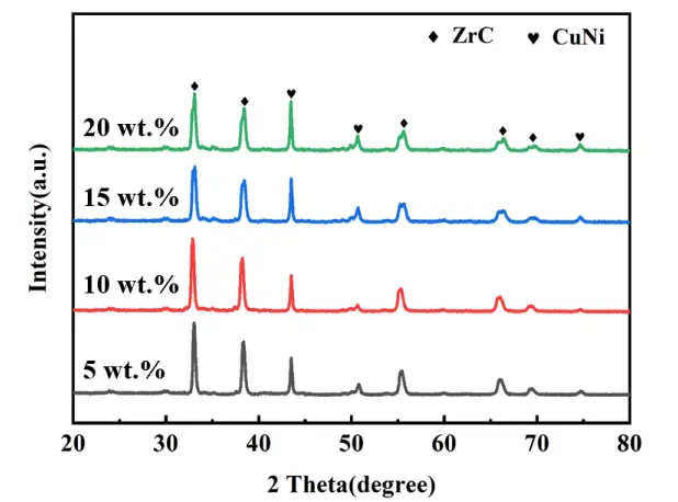
Figure 5. XRD patterns of Csf/C-ZrC-CuNi composites with different mass fractions of short carbon fiber.
Figure 6 presents SEM micrographs of the four composite specimens. Low-magnification images reveal that all composites possess dense and uniform surfaces free of macroscopic pores, cracks, or phase segregation, which verifies the uniform mixing of each component and stable sintering process. Short carbon fibers are randomly and discretely distributed within the matrix, with a diameter of approximately 10 μm and a length ranging from 100 to 150 μm. The volume density of fibers increases proportionally with their mass fraction. Further high-magnification observations of fiber-matrix interfaces (Figure 6a2–d2) reveal tiny, scattered microvoids in the bonding regions. These microvoids originate from volatile substance escape during sintering, volume shrinkage of molten CuNi alloy, and minor thermal stress release induced by the mismatch of thermal expansion coefficients between fibers and matrix. Nevertheless, the short carbon fibers maintain intact morphology without corrosion or structural damage after high-temperature sintering, proving that the adopted SPS parameters effectively densify the material while protecting carbon fibers from thermal degradation.
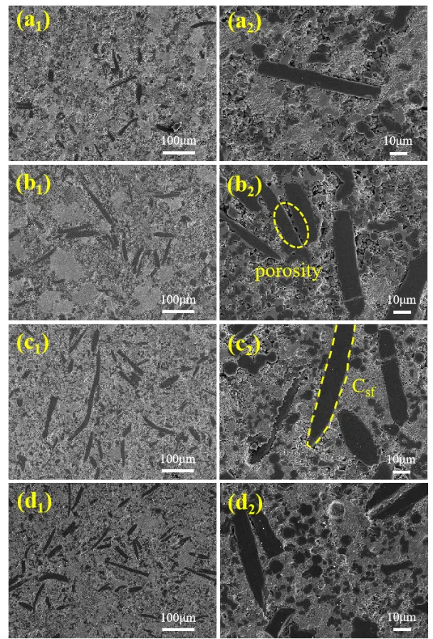
Figure 6. SEM images of Csf/C-ZrC-CuNi composites with different short carbon fiber contents: (a1,a2) 5 wt.%, (b1,b2) 10 wt.%, (c1,c2) 15 wt.%, (d1,d2) 20 wt.%.
Elemental mapping results of C, Cu, Ni, and Z for each composite are shown in Figure 7. Black domains represent carbon spheres and short carbon fibers, and gray areas correspond to the ZrC-CuNi matrix. All elements are distributed homogeneously, with no obvious segregation or aggregation. The interface between carbon fibers and the ZrC-Cu matrix is compact and crack-free, which benefits effective load transfer and mitigates stress concentration under external loading, improving the overall mechanical stability of composites at high temperatures.
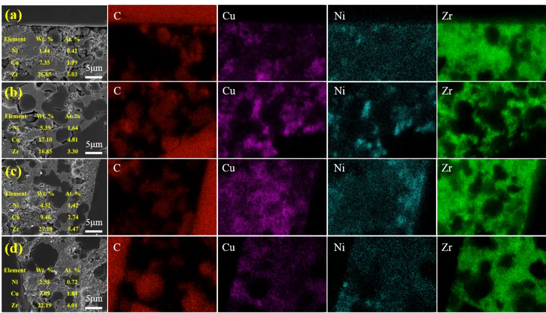
Figure 7. Elemental distribution mapping of C, Cu, Ni, and Zr in composites with different short carbon fiber contents: (a) 5 wt.%, (b) 10 wt.%, (c) 15 wt.%, (d) 20 wt.%.
3.5. Mechanical Properties of Csf/C-ZrC-CuNi Composites
Figure 8a shows load-displacement curves of the composites. All specimens exhibit linear elastic deformation at the initial loading stage, complying with Hooke’s law. When the applied load reaches the ultimate bearing capacity, sudden brittle fracture takes place. The slope of load-displacement curves increases gradually with increasing fiber content, reflecting the enhanced stiffness and load-bearing capacity of the composites. As high-strength short carbon fibers share external loads and disperse concentrated stress, the mechanical performance is significantly improved.
Figure 8b illustrates the variation of flexural strength against fiber mass fraction. The flexural strength values of 5 wt.%, 10 wt.%, 15 wt.%, and 20 wt.% samples are 43.8 MPa, 53.1 MPa, 56.7 MPa, and 66.3 MPa, respectively. The upward trend is attributed to the reinforcing effect of uniformly dispersed short carbon fibers: fibers undertake most external loads, retard crack propagation, and release interfacial stress. Moderate fiber-matrix interfacial bonding enables fiber pull-out and debonding behaviors to consume fracture energy, further boosting the bending resistance of the material.
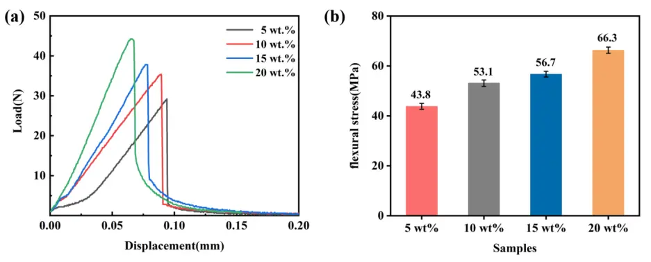
Figure 8. (a) Load-displacement curves and (b) flexural strength of Csf/C-ZrC-CuNi composites with different short carbon fiber contents.
Figure 9 displays fracture morphologies of the four groups of composites. Three typical failure modes, fiber pull-out, fiber-matrix debonding, and matrix fracture, can be clearly observed. The quantity and pull-out length of carbon fibers increase significantly as fiber content rises. A longer fiber pull-out length indicates an appropriate interfacial bonding strength between the fiber and the matrix. Energy dissipation occurs through friction during fiber extraction, interface separation, and crack deflection, which jointly enhance the fracture toughness of composites. The dispersed carbon fibers hinder crack propagation paths and relieve stress concentration, thereby greatly improving the load-bearing capacity of the matrix.
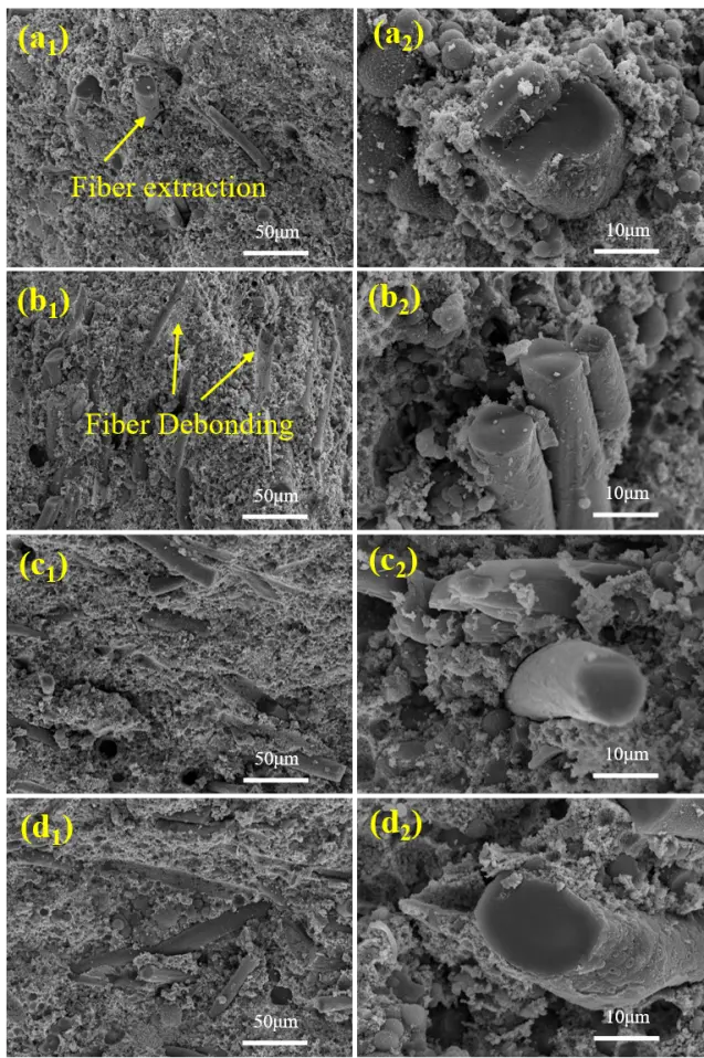
Figure 9. Fracture morphologies of composites with different short carbon fiber contents: (a1,a2) 5 wt.%, (b1,b2) 10 wt.%, (c1,c2) 15 wt.%, (d1,d2) 20 wt.%.
3.6. Ablation Resistance of Csf/C-ZrC-CuNi Composites
3.6.1. Ablation Behavior
Figure 10a presents the macroscopic morphology of composites with different short carbon fiber contents after oxyacetylene ablation. A white oxide film forms on the surface of all four samples, and the boundary between the ablation center and transition zone is indistinct. The composite containing 5 wt.% carbon fiber shows obvious cracking after ablation. As the fiber content rises to 10 wt.%, the cracking phenomenon is greatly suppressed. No cracks are observed on samples with 15 wt.% and 20 wt.% short carbon fibers after cooling following ablation. This demonstrates that short carbon fibers can effectively alleviate the inherent brittleness of ceramic matrices. Nevertheless, severe spalling and swelling cracking of the oxide scale emerge in the 15 wt.% and 20 wt.% specimens. Excess carbon fibers lead to a large mismatch in thermal expansion coefficients between fibers and the matrix. During heating and cooling cycles after ablation, differential shrinkage generates residual stress at fiber-matrix interfaces, which ultimately triggers peeling and cracking of the oxide layer.
Figure 10b shows the surface temperature curves measured at the ablation center of samples subjected to 60 s oxyacetylene ablation. The temperature evolution trend is similar for all groups: the temperature rises sharply within the first several seconds, peaks at around 15 s, and then maintains a stable plateau. However, the peak temperature differs noticeably with fiber content. The peak temperature decreases first and then increases as the fiber mass fraction grows. The 10 wt.% sample achieves the minimum peak temperature of 2268 °C, which can be attributed to the uniform oxide film formed on its surface that elevates emissivity and facilitates heat dissipation. By contrast, the peak temperatures of 15 wt.% and 20 wt.% samples reach 2494 °C and 2544 °C, respectively, because partial oxide spalling exposes the substrate to high-temperature oxidative flame and aggravates thermal erosion.
Figure 10c displays XRD patterns of ablated composites after 60 s flame exposure. The main ablation products are ZrO2, NiO, Cu2O, and CuO. NiO and Cu2O are mainly generated during the oxyacetylene ablation test at ultra-high temperature, oxygen is primarily supplied by an enriched oxyacetylene flame. CuO forms secondarily during the cooling stage via the oxidation of Cu2O in air, as CuO is thermodynamically unstable at ultra-high temperatures above 1120 °C. This confirms that Cu2O serves as the dominant liquid-phase oxide during ablation, while CuO is merely a low-temperature cooling product.
Figure 10d,e illustrate the mass ablation rate (MAR) and linear ablation rate (LAR) of the four composites. The mass ablation rate increases monotonically with rising fiber content: the 5 wt.% sample exhibits the lowest MAR of 1.41 mg/s, while the 20 wt.% sample reaches a maximum of 9.36 mg/s. The extremely high mass loss of the 20 wt.% composite originates from severe interfacial residual stress induced by excessive carbon fibers, which causes widespread oxide cracking and massive material peeling after ablation. All samples yield negative linear ablation rates, meaning the thickness of each specimen increases after ablation. This phenomenon stems from volume expansion that accompanies the oxidation of carbide phases to metal oxides. Among all groups, the 10 wt.% composite has the minimum linear ablation rate of −3.20 μm/s, whereas the 5 wt.% sample shows the maximum value of −5.15 μm/s.
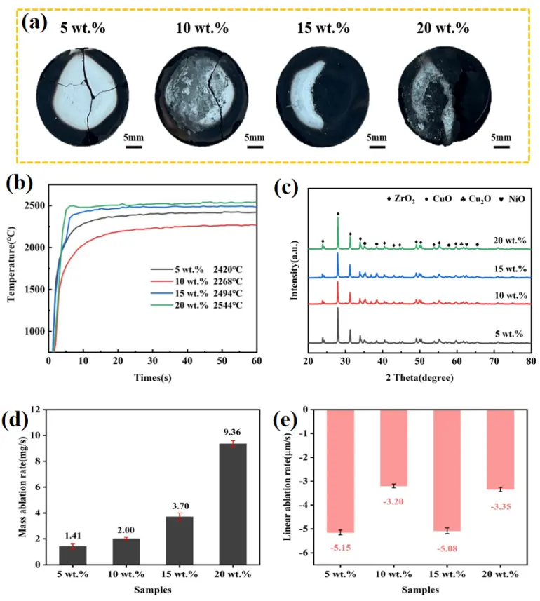
Figure 10. (a) Macroscopic appearance, (b) center surface temperature curve, (c) XRD patterns, (d) mass ablation rate and (e) linear ablation rate of composites with different short carbon fiber contents after ablation.
Figure 11a1 shows the micromorphology and EDS results of the ablation center of the 5 wt.% composite. A porous molten ZrO2 skeleton is formed at the central region, as identified by EDS elemental analysis. Numerous microcracks and micron-scale pores are distributed throughout the skeleton. Microcracks arise from thermal stress release during cooling due to the poor thermal shock resistance of pure ZrO2, while regular pores derive from the escape of CO, CO2, and gaseous Cu2O, and irregular voids are generated by incomplete melting of ZrO2.
Figure 11a1–d1 present the central microstructures of composites with varying fiber fractions. Complete oxidation of all carbon fibers occurs at the high-temperature ablation center for every sample. As short carbon fiber content increases, the porosity of the molten ZrO2 skeleton gradually declines, and ZrO2 grains bond more tightly together. Carbon fibers oxidize to produce CO2 gas, which reacts with Cu to generate more liquid Cu2O and NiO during ablation. These molten oxides act as sintering aids to bind loose ZrO2 particles and form a compact protective layer that blocks further flame and oxygen erosion. However, obvious large-scale cracking can be observed on the ZrO2 skeleton of the 20 wt.% composite. Excessive fibers create severe thermal expansion mismatch with the matrix, leading to massive residual stress during cooling and consequent rupture of the oxide barrier, which directly exposes the substrate to flame erosion and accelerates material damage.
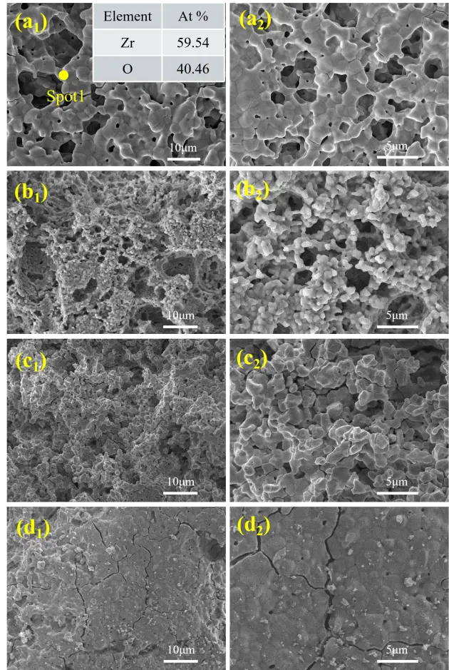
Figure 11. Micrographs of ablation centers for composites with different short carbon fiber fractions: (a1,a2) 5 wt.%, (b1,b2) 10 wt.%, (c1,c2) 15 wt.%, (d1,d2) 20 wt.%.
Figure 12 shows the microstructural morphology and EDS spectrum of the ablation transition zone in the Csf/C-ZrC-CuNi composite material with a carbon fiber mass fraction of 5 wt.%. Compared to the ablation center region, the transition zone, subjected to relatively lower thermal flux, forms a more complete and dense protective layer structure on the material surface, with the number of cracks and pores being significantly reduced. Observation reveals that the ablation transition zone of the composite material consists of a molten, highly dense matrix phase and a fine particle phase uniformly distributed on the matrix surface. EDS energy-dispersive spectroscopic analysis indicates that the primary constituent of the matrix phase is high-melting-point ZrO2, while the dispersed fine particles are mainly composed of Cu2O and NiO. Due to their low melting points, Cu2O and NiO remain in a liquid state during the ablation process; this liquid phase effectively fills the voids and cracks between the ZrO2 particles, thereby forming a continuous coating on the material surface that effectively shields the base material from further erosion by high-temperature flames and high-velocity gas streams, enhancing the ablation resistance of the composite material.
The microstructural morphology of the ablation transition zone in Csf/C-ZrC-CuNi composite materials with carbon fiber mass fractions of 10 wt.%, 15 wt.%, and 20 wt.% is shown in Figure 13. Observation reveals that the ablation transition zone of the composite material consists of high-melting-point ZrO2 and low-melting-point Cu2O and NiO; Cu2O and NiO are uniformly distributed as spherical particles on the ZrO2 matrix. This occurs because, under the high-temperature ablation conditions, the surface tension effect of the molten oxides drives them toward forming the spherical morphology, which corresponds to the state of lowest energy.
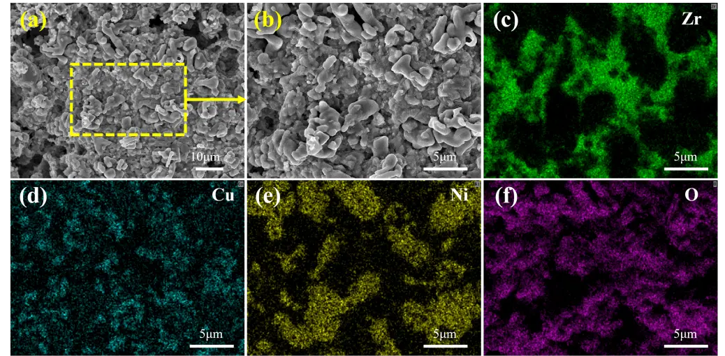
Figure 12. (a) Low-magnification SEM micrograph of the ablation transition zone; (b) enlarged view of the area marked by the yellow dashed box in (a); EDS elemental mapping of (c) Zr, (d) Cu, (e) Ni, and (f) O for the ablation transition zone of Csf/C‑ZrC‑CuNi composite with a carbon fiber mass fraction of 5 wt.%.
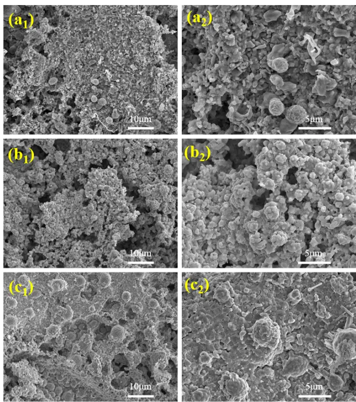
Figure 13. Microstructures of ablation transition zones: (a1,a2) 10 wt.%, (b1,b2) 15 wt.%, (c1,c2) 20 wt.%.
Figure 14 displays the microstructures of ablation edge regions. The edge area suffers milder ablation with lower ambient temperature, so the material retains a denser structure with negligible cracks and voids. A large amount of unoxidized CuNi alloy particles still remain in this zone and distribute uniformly among ZrO2 grains, constructing a dense metal-ceramic composite protective layer that enhances structural stability under high-temperature service conditions.
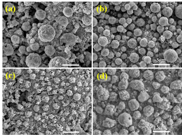
Figure 14. Micrographs of ablation edge regions for composites with different short carbon fiber contents: (a) 5 wt.%, (b) 10 wt.%, (c) 15 wt.%, (d) 20 wt.%.
3.6.2. Ablation Mechanism
To further analyze the phase behavior during the oxidation process of the composite material, we used the FactSage 7.3 software to plot the phase diagrams for ZrC–O2, Cu–O2, and Ni–O2, as shown in Figure 15. As seen in Figure 15a, when ZrC is exposed to an oxygen-rich environment, it oxidizes into ZrO2; at temperatures above 2715 °C, ZrO2 exists in a liquid state. From Figure 15b, it can be observed that below 1250 °C, Cu exists in the forms of CuO and Cu2O; when the temperature exceeds 1250 °C, CuO transforms into Cu2O due to its high-temperature instability and then exists in a liquid state. As depicted in Figure 15c, Ni reacts with O2 to form NiO; when the temperature exceeds 1955 °C, NiO transitions from the solid to the liquid state. According to Figure 10b, the surface temperature of the composite material during the ablation process is approximately 2000 °C; at this temperature, phase diagram analysis indicates that ZrO2, Cu2O(l), and NiO(l) coexist within the composite material. Notably, the presence of NiO(l) and Cu2O(l) in liquid form within the composite material can serve as a sintering aid, binding loose ZrO2 particles together and facilitating the formation of dense ZrO2 flake structures, thereby providing protection against the scouring and erosion effects of the flame during the ablation process.
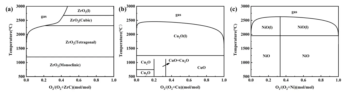
The possible chemical reactions occurring on Csf/C-ZrC-CuNi composites during ablation are listed as follows; the standard Gibbs free-energy values of Reactions (4)–(14) in this work are extracted from the FactSage thermodynamic database, instead of being newly calculated in the present study.
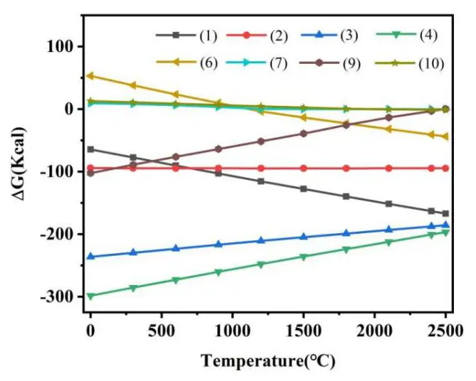
Figure 16 plots the variation of standard Gibbs free energy (ΔG) of reactions ((4)–(7), (9) and (10), (12) and (13)) with temperature. Thermodynamic calculation results reveal that ZrC is preferentially oxidized over carbon fibers during ablation due to the lower ΔG values of reactions (6) and (7). According to reaction (9), CuO is metastable at high temperatures and transforms into Cu2O above approximately 1120 °C, indicating Cu2O is the primary high-temperature oxidation product, while CuO is only generated in the cooling stage. As shown in reaction (14), CO2 produced by the oxidation of carbon fibers further reacts with Cu to generate more Cu2O, which indirectly promotes the oxidation of Cu.
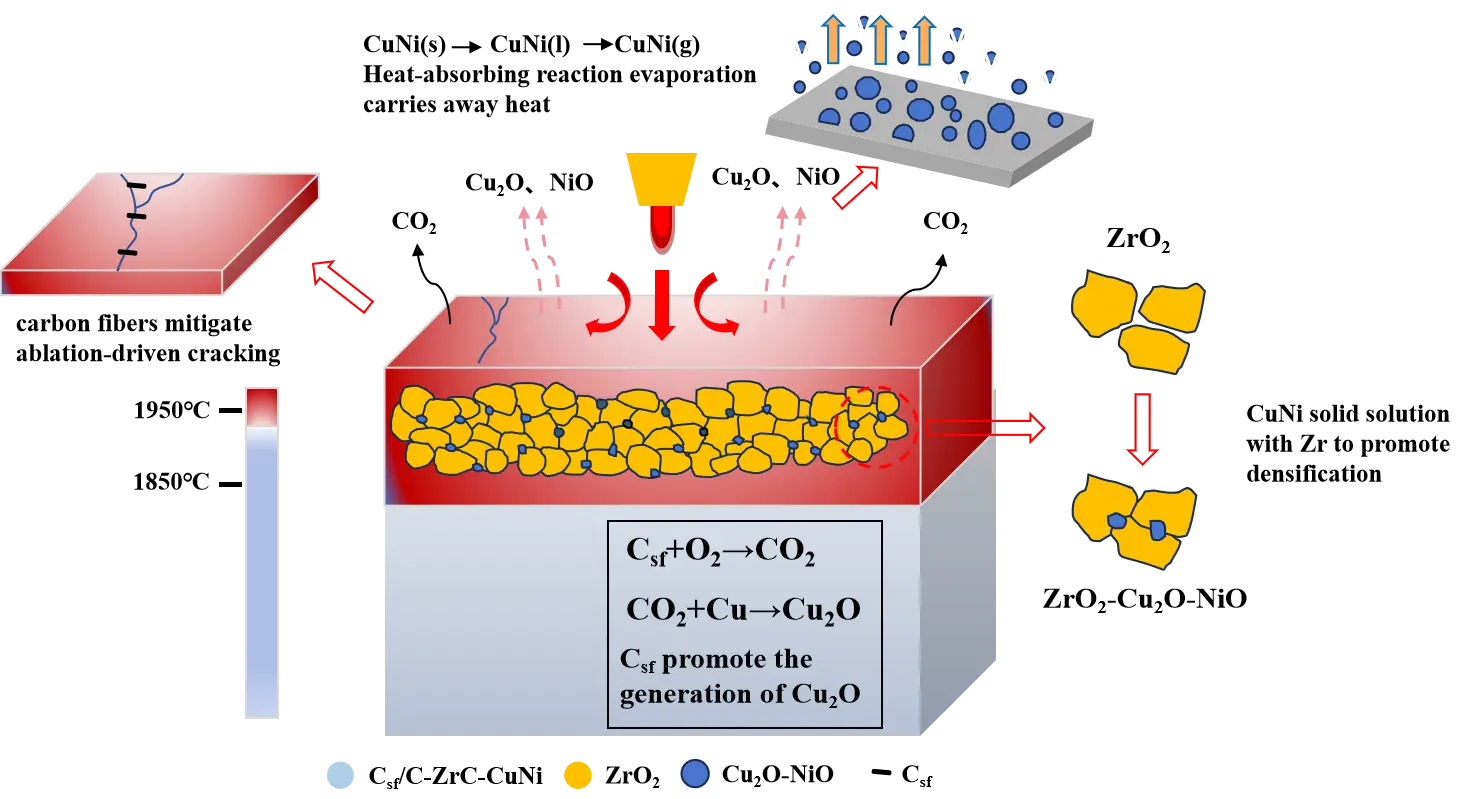
The outstanding ablation resistance of Csf/C-ZrC-CuNi composites originates from the synergistic effect of CuNi alloy and short carbon fibers. During ablation, CuNi alloy undergoes solid-liquid-gas phase transitions, all of which are endothermic reactions that consume massive heat and reduce the surface temperature of ablated samples. In particular, the vaporization of molten Cu2O absorbs enormous vaporization latent heat and delivers an efficient transpiration cooling effect to dissipate heat rapidly. Appropriate addition of short carbon fibers reduces the porosity and improves the density of composites. Higher density facilitates heat conduction inside the material. Benefiting from high specific strength and high specific modulus, short carbon fibers effectively eliminate the inherent ablation-induced cracking defect of ceramic materials and facilitate the formation of dense oxide layers on the sample surface. Moreover, carbon fibers accelerate the oxidation of Cu to generate abundant Cu2O. Both Cu2O and NiO exist as liquid phases at around 2000 °C and serve as sintering aids that bond discrete ZrO2 particles into a compact barrier layer, thereby inhibiting oxygen penetration and resisting erosion by ablation flames.
As shown in Figure 17, under oxy-acetylene ablation flame, the surface of Csf/C-ZrC-CuNi composite undergoes intense thermal shock and chemical oxidation. On the one hand, the incorporated short carbon fibers can effectively inhibit crack propagation caused by thermal stress during ablation, alleviating severe cracking failure of the material. Partial short carbon fibers are oxidized into CO2 under high-temperature flame, and the generated CO2 further reacts with Cu to produce Cu2O, which accelerates the formation of liquid Cu2O-NiO mixed oxides. Meanwhile, CuNi alloy experiences sequential melting and vaporization, and the heat-absorbing evaporation process takes away substantial surface heat to realize the transpiration cooling effect. The molten Cu2O-NiO mixture acts as a sintering binder, promoting the densification of the ZrO2 scale. The formed compact ZrO2-Cu2O-NiO composite barrier layer can hinder inward oxygen diffusion and flame erosion, protecting the inner matrix from further ablation damage.
4. Conclusions
In this work, surface-modified short carbon fibers were introduced to solve the problem of severe cracking and loose oxide layers of conventional C-ZrC-CuNi composites under high-temperature ablation. A series of Csf/C-ZrC-CuNi composites was fabricated via spark plasma sintering (SPS). The effects of short carbon fiber content on micromorphology, mechanical properties, and oxyacetylene ablation performance were systematically investigated, and the toughening and anti-ablation mechanisms were revealed by thermodynamic analysis combined with multi-scale microscopic characterization. The main conclusions are summarized as follows:
- (1)
-
The obtained Csf/C-ZrC-CuNi composites possess a compact macrostructure without obvious pores or cracks. Short carbon fibers (100–150 μm) are uniformly and randomly distributed within the matrix. Minor microvoids occur at fiber-matrix interfaces, originating from volatile-gas release during SPS processing.
- (2)
-
Short carbon fibers enhance the flexural strength via fiber pull-out and interfacial debonding. The 20 wt.%-Csf composite reaches the highest flexural strength of 66.3 MPa. As fiber content increases, the peak ablation temperature decreases first and then increases. The 10 wt.%-Csf sample delivers the best comprehensive ablation resistance, with the minimum ablation temperature of 2268 °C, mass ablation rate of 2.00 mg/s, and linear ablation rate of −3.20 μm/s.
- (3)
-
The outstanding ablation resistance of Csf/C-ZrC-CuNi composites originates from the synergistic effect between CuNi alloy and short carbon fibers. The CuNi alloy provides transpiration cooling to reduce surface temperature, while carbon fibers mitigate ablation-driven cracking. Moreover, carbon fibers facilitate Cu2O formation. Liquid Cu2O-NiO mixtures serve as sintering binders to construct dense ZrO2 barrier layers, which hinder oxygen diffusion and flame erosion toward the inner matrix.
Author Contributions
C.L. and H.O.: Writing—review & editing, Supervision, Project administration, Funding acquisition. Y.X.: Writing—original draft, Methodology, Investigation, Formal analysis, Conceptualization. S.Q.: Writing—review & editing, Supervision. X.W. (Xinnuo Wang): Validation, Data curation. X.N.: Validation, Data curation. X.W. (Xilin Wang): Investigation. X.S.: Investigation. S.Z.: Conceptualization. T.S.: Conceptualization. Y.L.: Conceptualization.
Ethics Statement
Not applicable.
Informed Consent Statement
Not applicable.
Data Availability Statement
Data will be made available on request.
Funding
This work was supported by the National Natural Science Foundation of China (Grant No. 52372087, 52173299), and the Natural Science Foundation of Shaanxi Province(Grant No. 2025SYS-SYSZD-062).
Declaration of Competing Interest
The authors declare that they have no known competing financial interests or personal relationships that could have appeared to influence the work reported in this paper.
References
- Csanádi T, Castle E, Reece MJ, Dusza J. Strength enhancement and slip behaviour of high-entropy carbide grains during micro-compression. Sci. Rep. 2019, 9, 10200. DOI:10.1038/s41598-019-46614-w [Google Scholar]
- Li J, Zhang Y, Fu Y, Li T, Zhang J, Yang D, et al. Twin toughening-driven martensitic transformation strategy synergistic improvement for plasticity-thermal shock resistance of (Hf–Zr–Ti)C ceramic coating in severe thermal environments. Adv. Sci. 2025, 12, e2503226. DOI:10.1002/advs.202503226 [Google Scholar]
- Jin R, Zhou Z, Liu J, Shi B, Zhou N, Wang X, et al. Aerogels for thermal protection and their application in aerospace. Gels 2023, 9, 606. DOI:10.3390/gels9080606 [Google Scholar]
- Wang D, Zhuang Q, Li K, Wang Y. Study on correlation of mechanical and thermal properties of coal-based carbon foam with the weight loss rate after oxidation. Materials 2022, 15, 4887. DOI:10.3390/ma15144887 [Google Scholar]
- Liu Y, Lin H, Zhou Y, Yuan L, Wang Y, Ma X, et al. Temperature-dependent infrared engineering for extreme environments: All-dielectric thermal photonic metamaterials stable at 1873 K in air. Nanomicro Lett. 2026, 18, 214. DOI:10.1007/s40820-025-02065-9 [Google Scholar]
- Jin E, Ma D, Yuan Z, Sun W, Wang H, Zhang J, et al. Influence of oxidation damages on mechanical properties of SiC/SiC composite using domestic hi-nicalon type Si fibers. Scanning 2020, 2020, 8840963. DOI:10.1155/2020/8840963 [Google Scholar]
- Le VT, Ha NS, Goo NS. Advanced sandwich structures for thermal protection systems in hypersonic vehicles. Compos. Part B Eng. 2021, 226, 109301. DOI:10.1016/j.compositesb.2021.109301 [Google Scholar]
- Uyanna O, Najafi H. Thermal protection systems for space vehicles: A review on technology development, current challenges and future prospects. Acta Astronaut. 2020, 176, 341–356. DOI:10.1016/j.actaastro.2020.06.047 [Google Scholar]
- Vasile BS, Birca AC, Surdu VA, Neacsu IA, Nicoară AI. Ceramic composite materials obtained by electron-beam physical vapor deposition used as thermal barriers in the aerospace industry. Nanomaterials 2020, 10, 370. DOI:10.3390/nano10020370 [Google Scholar]
- Yang Q, Li C, Ouyang H, Gao R, Shen T, Huang J. Dual-porosity (Ta0.2Nb0.2Ti0.2Zr0.2Hf0.2)C high-entropy ceramics with high compressive strength and low thermal conductivity prepared by pressureless sintering. Materials 2023, 16, 2495. DOI:10.3390/ma16062495 [Google Scholar]
- Han J, Wang Y, Liu R, Wan F. Theoretical and experimental investigation of xenotime-type rare earth phosphate REPO4 (RE = Lu, Yb, Er, Y and Sc) for environmental barrier coating applications. Sci. Rep. 2020, 10, 13681. DOI:10.1038/s41598-020-70648-0 [Google Scholar]
- Hu C, Hong W, Xu X, Tang S, Du S, Cheng HM. Sandwich-structured C/C-SiC composites fabricated by electromagnetic-coupling chemical vapor infiltration. Sci. Rep. 2017, 7, 13120. DOI:10.1038/s41598-017-13569-9 [Google Scholar]
- Bai L, Yuan F, Fang Z, Wang Q, Ouyang Y, Jin H, et al. RF thermal plasma synthesis of ultrafine ZrB2-ZrC composite powders. Nanomaterials 2020, 10, 2497. DOI:10.3390/nano10122497 [Google Scholar]
- Zhao K, Ye F, Cheng L, Yang J, Chen X. An overview of ultra-high temperature ceramic for thermal insulation: Structure and composition design with thermal conductivity regulation. J. Eur. Ceram. Soc. 2023, 43, 7241–7262. DOI:10.1016/j.jeurceramsoc.2023.07.046 [Google Scholar]
- Zhang C, Hu P, Xun L, Zhou Y, Han J, Zhang X. A universal strategy towards ultra-high temperature ceramic matrix composites with outstanding mechanical and ablation resistance. Compos. Part B Eng. 2024, 280, 111465. DOI:10.1016/j.compositesb.2024.111485 [Google Scholar]
- Musa C, Licheri R, Orrù R, Cao G, Sciti D, Silvestroni L, et al. Processing, mechanical and optical properties of additive-free ZrC ceramics prepared by spark plasma sintering. Materials 2016, 9, 489. DOI:10.3390/MA9060489 [Google Scholar]
- He Q, Li H, Wang C, Lu J. Influence of CLVD thermal gradient on the deposition behavior, microstructure and properties of C/C-ZrC composites. Ceram. Int. 2018, 44, 15631–15645. DOI:10.1016/j.ceramint.2018.05.232 [Google Scholar]
- Xu J, Guo L, Kong J, Ma Y, Wang H, Wang J. The mechanical properties of C/C-ZrC-SiC composites after laser ablation. J. Eur. Ceram. Soc. 2023, 43, 6732–6745. DOI:10.1016/j.jeurceramsoc.2023.07.045 [Google Scholar]
- Peterson GR, Carr RE, Marinero EE. Zirconium carbide for hypersonic applications, opportunities and challenges. Materials 2023, 16, 6158. DOI:10.3390/ma16186158 [Google Scholar]
- Wu Y, Tang J, Tang S, Chen YH, Chiu TW, Takeguchi M, et al. Stable field emissions from zirconium carbide nanoneedle electron source. Nanomaterials 2025, 15, 93. DOI:10.3390/nano15020093 [Google Scholar]
- Zhou H, Ni D, He P, Yang J, Hu J, Dong S. Ablation behaviour of C/C-ZrC and C/SiC composites fabricated by slurry impregnation combined with chemical vapor infiltration. Ceram. Int. 2018, 44, 4777–4782. DOI:10.1016/j.ceramint.2017.12.062 [Google Scholar]
- Dong Z, Yu H, Zhang Y, Liu B, Zhang H, Zhang J, et al. C/C-HfC-ZrC composites with excellent long-term ablation performance prepared by combining PIP and RMI. Ceram. Int. 2024, 50, 13912–13923. DOI:10.1016/j.ceramint.2024.01.308 [Google Scholar]
- Weng Y, Yang X, Chen F, Fang C, Zhang X, Shi A, et al. Ablative property of SiC-CuxSiy modified C/C-ZrC composites prepared by a rapid method. J. Eur. Ceram. Soc. 2023, 43, 4602–4615. DOI:10.1016/j.jeurceramsoc.2023.04.011 [Google Scholar]
- Kang BR, Kim HS, Oh PY, Lee JM, Lee HI, Hong SM. Characteristics of ZrC barrier coating on Si-coated carbon/carbon composite developed by thermal spray process. Materials 2019, 12, 747. DOI:10.3390/ma12050747 [Google Scholar]
- Liu QH, Tian T, Sun W, Zhang HB, Xiong X. Microstructure and ablation behaviour of Zr-based ultra-high-temperature gradient composites. Trans. Nonferrous Met. Soc. China 2024, 34, 2889–2899. DOI:10.1016/S1003-6326(24)66583-0 [Google Scholar]
- Zhong L, Guo L, Huang J, Liu N, Li Y, Li H. Ablation behavior of the ZrC coating on C/C composite with the construction of thermal dispersal network. Ceram. Int. 2023, 49, 13903–13915. DOI:10.1016/j.ceramint.2022.12.270 [Google Scholar]
- Li C, Li G, Ouyang H, Huang J, Hou X. Microstructure and properties of C/C-ZrC composites prepared by hydrothermal deposition combined with carbothermal reduction. J. Alloys Compd. 2018, 741, 323–330. DOI:10.1016/j.jallcom.2018.01.148 [Google Scholar]
- Li Y, Chen S, Hu H, Zou C, Chen Z, Ma X. A meltable precursor for zirconium carbide ceramics and C/C-ZrC composites. Ceram. Int. 2018, 44, 10175–10180. DOI:10.1016/j.ceramint.2018.03.007 [Google Scholar]
- Li C, Qi S, Ouyang H, Shen T, Chen Z, Li Y, et al. Microstructure and properties of C/C-ZrC-CuNi composites prepared by a PIP method using inorganic salt as a precursor. J. Alloys Compd. 2025, 1025, 180326. DOI:10.1016/j.jallcom.2025.180326 [Google Scholar]
- Zhang Y, Liu B, Hu D, Zhang Y, Ren B, Wang X, et al. ZrC modified carbon/carbon composites using ZrSi2 and Zr-Cu alloys as reactive infiltrating materials: A comparative investigation. J. Alloys Compd. 2024, 1003, 175515. DOI:10.1016/j.jallcom.2024.175515 [Google Scholar]
- Xu B, Shi M, Wang Y, Wang F, Huang Z. Enhancing high temperature bearing capacity and oxidation resistance for Ni-coated carbon fibers reinforced composites via in-situ ceramization and catalytic graphitization. Ceram. Int. 2025, 51, 3086–3096. DOI:10.1016/j.ceramint.2024.11.284 [Google Scholar]
- Kou G, Guo L, Li H. Effect of copper on heat erosion mechanism of C/C composites. J. Alloys Compd. 2017, 723, 1132–1141. DOI:10.1016/j.jallcom.2017.06.278 [Google Scholar]
- Guo X, Si X, Shang X, Dong C, Xiao Z, Li C, et al. Understanding wetting mechanism of pure Cu on chromium carbide modified C/C composites. Mater. Charact. 2023, 206, 113439. DOI:10.1016/j.matchar.2023.113439 [Google Scholar]
- Ahangarkani M, Zangene-Madar K, Borji S. Transpiration cooling during ultra-high temperature erosion. Mater. Lett. 2018, 211, 203–207. DOI:10.1016/j.matlet.2017.10.015 [Google Scholar]
- Xu J, Sun W, Xiong X, Zhang H, Yang L. Mechanical properties, thermophysical properties, and long-term ablation behaviours of C/C–ZrC–ZrB2–W–Cu composites. Ceram. Int. 2024, 50, 38471–38484. DOI:10.1016/j.ceramint.2024.07.212 [Google Scholar]
- Li H, He Q, Wang C, Lu J. Effects of precursor feeding rate on the microstructure and ablation resistance of gradient C/C ZrC SiC composites prepared by chemical liquid-vapor deposition. Vacuum 2019, 164, 265–277. DOI:10.1016/j.vacuum.2019.03.030 [Google Scholar]
- Zeng X, Men Z, Deng F, Chen C. Optimization of the Heat Dissipation Performance of a Lithium-Ion Battery Thermal Management System with CPCM/Liquid Cooling. Materials 2022, 15, 3835. DOI:10.3390/ma15113835 [Google Scholar]
- Dong L, Tang Y, Li X, Zhang S, Zhang W, Fu Y, et al. Elevated temperature ablation mechanisms of Cu@rGO/CuW nanocomposites under oxyacetylene torch flame. J. Mater. Res. Technol. 2023, 27, 6709–6718. DOI:10.1016/j.jmrt.2023.11.158 [Google Scholar]
- Li H, Yang X, Chen F, Weng Y, Yan Q, Yan J, et al. Tuning ceramic content, mechanical and ablative properties of C/C–ZrC-ZrxCuy composites via using various C/C skeletons. Ceram. Int. 2023, 49, 12173–12185. DOI:10.1016/j.ceramint.2022.12.069 [Google Scholar]
- Ahangarkani M. The effect of contamination and skeleton fracture mode on ablation uniformity in W-Cu composite. Int. J. Refract. Met. Hard Mater. 2018, 72, 15–20. DOI:10.1016/j.ijrmhm.2017.12.002 [Google Scholar]
- Xu J, Sun W, Xiong X, Zhang H, Yang L. Outstanding mechanical and ablation resistance of C/C–ZrC–W composites prepared via slurry impregnation and reactive melt infiltration at 1500 °C. J. Alloys Compd. 2024, 976, 173137. DOI:10.1016/j.jallcom.2023.173137 [Google Scholar]
- Zheng L, Luo X, Fang C, Zeng C, Zhang X, Zhang Z, et al. Ablation behaviour and mechanism of Mg-modified ZrC-SiC composite in plasma ablation flame. Corros. Sci. 2022, 206, 110523. DOI:10.1016/j.corsci.2022.110523 [Google Scholar]
- Wang S, Yin J, Xiefeng M, Tang L, Xiong X, Zhang H, et al. Microstructure and ablation behaviour of C/C-SiC-ZrC-Cu composites prepared by reactive melt infiltration. Mater. Today Commun. 2024, 38, 108389. DOI:10.1016/j.mtcomm.2024.108389 [Google Scholar]
- Weng Y, Yang X, Chen F, Zhang X, Shi A, Yan J, et al. Structure evolution and ablative mechanism of C/C-ZrC-ZrxCuy composites with low porosity fabricated by pressure assisted reactive melt infiltration. Corros. Sci. 2022, 209, 110801. DOI:10.1016/j.corsci.2022.110801 [Google Scholar]
- Sha JJ, Li J, Wang SH, Wang YC, Zhang ZF, Dai JX. Toughening effect of short carbon fibers in the ZrB2–ZrSi2 ceramic composites. Mater. Des. 2015, 75, 160–165. DOI:10.1016/j.matdes.2015.03.006 [Google Scholar]
- Zhang K, Chen Y, Weng L, Cheng S, Yu S, Zeng T. Fabrication of dense Cf/SiC ceramic matrix composites using 3D printing and PIP with short carbon fibre as a toughening material. Virtual Phys. Prototyp. 2024, 19, e2425381. DOI:10.1080/17452759.2024.2425381 [Google Scholar]
- Hu K, Deng J, Mao Y, Kou S, Wang B, Fan S. Feasibility and ablation behavior of on‑site HfSi2 and HfSi2‑HfO2 repair coatings on C/C‑SiC‑ZrC composites. Ceram. Int. 2025, 51, 65537–65550. DOI:10.1016/j.ceramint.2025.11.231 [Google Scholar]