
Progress of Triboelectric Nanogenerators Based on Bionic and Flexible Mechanisms for Wave Energy Collection System
Progress of Triboelectric Nanogenerators Based on Bionic and Flexible Mechanisms for Wave Energy Collection System
Yudeng Lin 1 Zhicheng Liu 1 Kefan Yang 1 Shengqing Zeng 1 Dapeng Zhang 1,2,*
Received: 31 May 2026 Revised: 11 August 2026 Accepted: 14 August 2026 Published: 31 August 2026

© 2026 The authors. This is an open access article under the Creative Commons Attribution 4.0 International License (https://creativecommons.org/licenses/by/4.0/).
1. Introduction
Wave energy, as an abundant and widely distributed clean renewable resource, holds significant strategic value for addressing the global energy crisis and climate change. However, the inherent low-frequency, stochastic, and multidirectional characteristics of ocean waves render conventional electromagnetic generation technologies inefficient in complex marine environments, resulting in low conversion efficiency, intricate structures, and high maintenance costs. Triboelectric nanogenerators (TENGs), owing to their unique advantage in harvesting low-frequency mechanical energy, have emerged in recent years as a research hotspot in wave-energy harvesting. Notably, the incorporation of biomimetic and flexible mechanisms has opened new avenues to enhance the adaptability, robustness, and overall performance of TENGs under realistic sea conditions.
In recent years, several review articles have summarized advances in TENGs for blue-energy harvesting, covering device architectures, material optimization, and power-management strategies. Nonetheless, most existing reviews focus on generic TENG design principles or the broad application of wave energy, lacking a systematic analysis of the synergistic effects and design methodologies of biomimetic and flexible strategies in wave-energy collection. Moreover, a critical assessment of the advantages and limitations of various biomimetic-flexible approaches, as well as a clear development roadmap, remains absent from the literature. Given the rapid progress in biomimetic design and flexible structural innovations, a comprehensive review that systematically examines these strategies is urgently needed.
To fill this gap, this paper provides a systematic review of the latest research on biomimetic and flexible-mechanism-based TENGs for wave-energy harvesting. First, the fundamental operating principles of TENGs and their four working modes are elucidated. Then, drawing on three aspects—biomimetic directional adaptation, enhanced response at low flow speeds, and durable environmental interfaces—the review summarizes biomimetic design strategies inspired by organisms such as sunflowers, fish schools, kelp, whale sharks, and lotus leaves. Subsequently, the contributions of flexible materials, flexible architectures, and interfacial lubrication to improving TENG environmental adaptability are analyzed. Building on this foundation, the performance differences among various biomimetic-flexible strategies in terms of power density, startup threshold, and durability are compared, and their potential in typical applications such as self-powered environmental monitoring, array deployment, and marine buoy power supply is demonstrated. The discussion then delves into current technical bottlenecks, including insufficient reliability under extreme sea states, the lack of unified design methodologies, complex manufacturing processes, and inadequate testing standards. Finally, future development directions are outlined, encompassing environmentally adaptive materials, multifunctional biomimetic co-design, modular array deployment, and long-term field validation, with the aim of providing a systematic reference for wave-energy harvesting and marine self-powered systems research [1,2,3,4,5,6,7,8,9,10,11,12].
2. Basic Theory of Triboelectric Nanogenerators
2.1. Working Principle
The triboelectric nanogenerator (TENG) was proposed by Professor Zhonglin Wang and others in 2012. It combines triboelectrification and electrostatic induction effects to convert irregular, low-frequency, and low-amplitude mechanical energy (which has significant advantages in harvesting low-frequency, irregular wave energy) into electrical output, showing broad application prospects in capturing blue ocean energy. [13,14,15]. Professor Zhonglin Wang and colleagues [16] conducted research on solid-solid triboelectrification and concluded that electron transfer is the primary mechanism of solid-solid triboelectrification. When the interatomic distance between two materials is shorter than the normal bond length (usually about 2 nanometers), electron transfer can occur. The reduction of the interatomic potential barrier allows strong electron cloud overlap between two atoms in the repulsive region, leading to electron transitions between atoms, generating equal amounts of positive and negative charges on the surfaces of the two dielectrics, that is, triboelectrification. After separating the two dielectrics, corresponding charges are induced on the outer surfaces of the electrodes of the two dielectrics by electrostatic induction, and then current flows in the external circuit. The operating principle of a triboelectric nanogenerator (TENG) is grounded in Maxwell’s displacement current, the fundamental theory governing charge generation and transfer. The displacement current consists of a time-varying electric-field component (an electric field that evolves with time) and a surface electrostatic polarization component (an electric-field effect induced by static charges accumulated on the material surface). Their intrinsic dielectric constant determines the degree to which different materials respond to this electric-field effect. This framework elucidates the mechanism by which mechanical motion is converted into electrical output and demonstrates that both material properties and environmental conditions dictate charge density and energy-conversion efficiency [17,18,19,20,21,22,23,24].
2.2. Five Working Modes of Triboelectric Nanogenerators
TENGs mainly operate based on the following four working modes: vertical contact-separation mode, lateral sliding mode, single-electrode mode, and independent layer mode [12,13,21]. Each of these four modes has its own typical structure, advantages and disadvantages, application scenarios, and factors affecting output power, and should be used flexibly according to the actual situation. Figure 1 shows four working modes, and Table 1 compares the advantages and disadvantages of different working modes and the factors affecting output power [18,25,26,27,28,29,30,31].
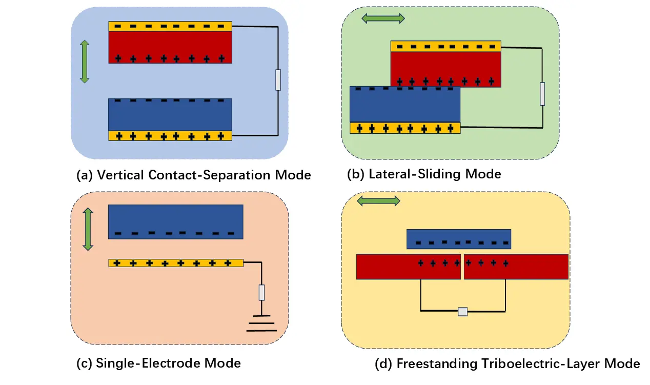
1. Vertical Contact-Separation Mode: This mode consists of two dielectric films with metal electrodes coated on their backside, with differing electron affinities. By applying an external force in the vertical direction, the two dielectric materials periodically contact and separate, generating an AC output in the external circuit. Upon contact, equal amounts of opposite charges are deposited on the surfaces, and an induced potential difference occurs upon separation. By connecting the back metal electrodes through a load, the induced potential difference drives free electrons to flow through the external circuit; upon subsequent contact, the potential difference disappears, and the electrons return to the original electrodes, repeating the cycle.
2. Lateral Sliding Mode: This mode consists of two materials with opposite triboelectric polarities with metal electrodes on the back. Its principle is similar to the vertical contact-separation mode. External force drives the two materials to slide back and forth horizontally, causing the dielectric films to continuously contact and separate, allowing electrons to transfer back and forth on the electrodes at the back of the materials.
3. Single-Electrode Mode: This mode involves connecting a load to a single electrode, with the other end of the load serving as the triboelectrification contact surface and charge collection surface, acting only as a potential reference electrode, or can be directly grounded. The movement range of the contact surface is not limited by the wire length. Movement of the two contact surfaces in horizontal or vertical directions drives electrons between the electrode and the reference electrode. However, the electrostatic shielding effect can reduce the efficiency of electron transfer.
4. Independent Layer Mode: This mode consists of a pair of fixed electrodes with a gap and a freely movable dielectric film. Applying an external force moves the dielectric film from contacting the left electrode to the right electrode, generating an induced potential difference between the two electrodes, causing electrons to flow from the right electrode to the left electrode. When the dielectric film moves from contacting the right electrode to the left electrode, electrons flow back. The reciprocal motion of the dielectric film between the two electrodes produces an AC output.
5. The current TEGNs based on air breakdown: Unlike the aforementioned four conventional alternating current (AC) modes, a unique direct current (DC) mode based on air breakdown has garnered significant attention in recent years as a highly promising alternative. This mode does not rely solely on electrostatic induction for AC output; instead, it leverages the electrostatic discharge (ESD) effect, in which accumulated surface charges trigger air breakdown across a microscopic gap, generating unidirectional current that obviates the need for external rectifiers. Through the inherent electron avalanche effect during breakdown, current can be amplified to the milliampere or even ampere level, representing a substantial enhancement over conventional TENG outputs. Recent investigations have further elucidated and manipulated the multi-domain discharge characteristics within DC-TENGs, leading to a tenfold increase in output power across a broad range of resistive loads.
Table 1. Comparison of advantages and disadvantages of different working modes and factors affecting output power.
|
Working Mode |
Advantages |
Disadvantages |
Factors Affecting Output Power |
|---|---|---|---|
|
Vertical Contact-Separation |
Simple structure, easy to fabricate, easy to integrate, high output voltage |
Not conducive to packaging, requires close contact with materials |
Separation distance, degree of contact, surface charge density |
|
Horizontal Sliding |
Simple structure, easy to package, high energy conversion efficiency |
Materials easily wear out, and large device size |
Device size, sliding distance, surface charge density |
|
Single Electrode |
The friction layer can move freely, and the easy wire connection |
Low output performance |
Sliding distance, separation distance, surface charge density |
|
Independent Layer |
Good stability, the friction layer can move freely, and easy wire connection. |
Requires a certain sliding frequency; materials easily wear out |
Sliding frequency, electrode spacing, surface charge density |
3. Bionic Structures
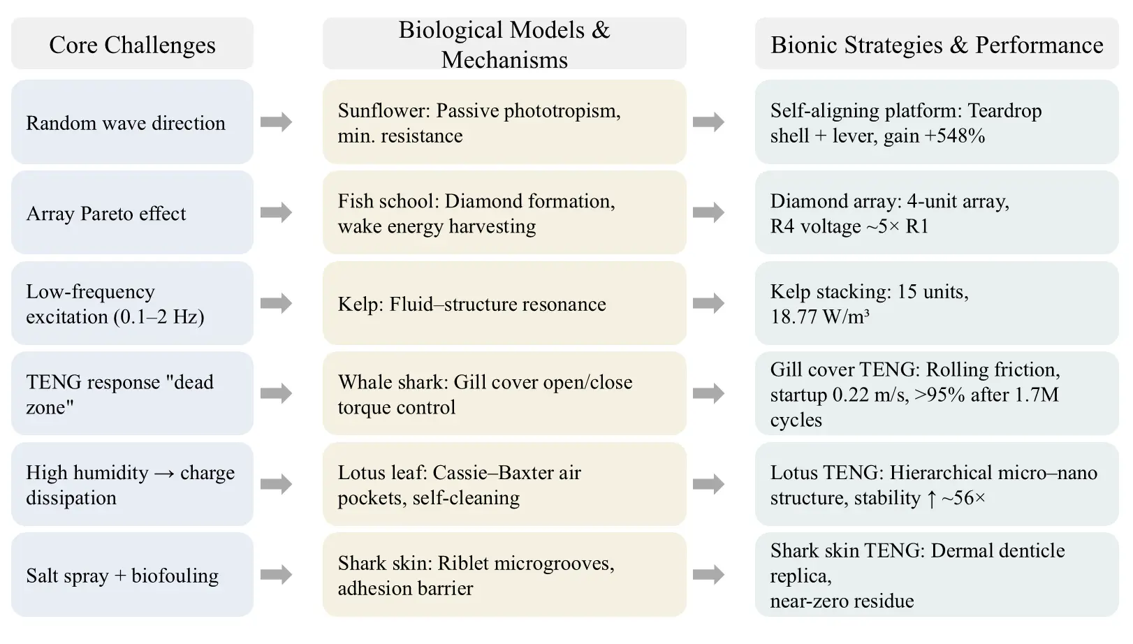
Ocean wave energy is generally considered a type of blue energy with high reserves, with a global theoretical potential of up to 29,500 TWh/year. However, the actual utilization is not as ideal as the theoretical value. Waves themselves have obvious randomness, especially in real sea conditions, where wave direction and wave height constantly change, directly affecting energy harvesting efficiency. Studies have shown that traditional electromagnetic power generation methods have limited output efficiency under low-frequency waves, while TENGs have certain advantages in collecting low-frequency mechanical energy, making them an increasingly important direction in wave energy research in recent years [30]. Figure 2 shows the strategy of the bionic panels for wave energy harvesting. Currently, most marine TENGs are still limited to laboratory conditions. Once they enter real marine environments, the problems increase significantly. One of the most troublesome issues in real sea conditions is that the wave direction is not fixed. Many devices perform well under a single directional excitation, but the output significantly drops when the wave direction changes. Secondly, under low flow or weak wave conditions, some TENGs are difficult to start stably and have obvious low-response intervals. Additionally, the marine environment itself can corrode the devices. Salt spray, high humidity, and even marine biofouling can affect interface charge stability, and over time, material aging becomes more pronounced. Marine organisms, which exist long-term in complex flow environments, inherently contain a large number of passive adaptation features in their forms and movements. These passive adaptation mechanisms in natural structures provide a useful reference for the subsequent design of marine TENG structures. For example, sunflowers can achieve passive orientation adjustment through asymmetric structures, kelp can still exhibit noticeable swaying in low-frequency water flow, and the micro-nano structures on lotus leaves have good self-cleaning ability. The passive adaptation mechanisms in these natural structures have a certain reference value for the subsequent design of marine TENG structures. The following content mainly focuses on three aspects: directional adaptation, low-flow response, and environmental durability [32,33,34,35,36,37,38,39,40,41,42,43,44].
3.1. Bionic Orientation and Posture Adaptation Strategies
For ocean TENG, wave direction changes have always been a relatively practical issue. In real sea conditions, the direction of wave propagation is usually distinctly discrete and changes over time [30]. Therefore, some structures optimized only for fixed directions often produce unstable outputs in real-world environments. Currently, some multidirectional array solutions can alleviate orientation issues, but they also tend to lead to structural complexity and energy dispersion. Qiu et al. pointed out that many existing TENG designs still rely on the assumption of “deterministic drive”, so when facing random wave excitation, the output often exhibits intermittent pulse characteristics [45]. Against this backdrop, this section mainly discusses bionic strategies inspired by sunflowers and fish schools from two aspects: overall platform orientation and array synergy, while also offering ideas for improving the performance of other bionic structures [46,47].
1. Passive self-alignment platform inspired by sunflower phototaxis: Sunflowers can achieve passive light attraction through asymmetric growth moments. Inspired by this, Li and others designed a butterfly stack TENG integrated with an alignment platform [48], as shown in Figure 3a. When waves do not propagate directly onto the platform, an asymmetric pressure distribution forms on both sides of the droplet-shaped shell. Under the influence of a lateral pressure difference, the platform can automatically rotate, gradually aligning its long axis with the direction of the wave. The entire process does not rely on additional electronic control systems, so the structure is relatively simple. The platform also features a lever amplification mechanism. The short arm receives high-torque, low-amplitude movements brought by high-density seawater. After pivot conversion, the long arm can output small-torque, high-amplitude swings, with the overall amplitude amplified by about 1.6 times [48]. This design is actually quite clever because it does not introduce additional complex control systems. Experimental results show that, compared with direct floating TENG, the platform’s output charge increases by about 548%. Under a wave amplitude of about 7 cm in the Beibu Gulf, a single BS-TENG transfers 2.54 μC of charge within 30 s, with an output current of 132.97 μA and a voltage of 146.52 V, successfully driving calculators and electronic watches [48]. Current experimental results show that this type of structure has demonstrated a certain adaptability to changes in wave direction.
2. Formation synergistic enhancement inspired by fish rhombus formations: When fish march in formation, individuals behind use the vortex energy in the wake ahead to reduce swimming energy consumption. Based on this mechanism, Zhang and others proposed the fish school effect TENG array [49], as shown in Figure 3b. In traditional blunt body arrays, adjacent blunt bodies cause proximity or wake effects due to different spacing, resulting in weakened vibration amplitude. Traditional control methods can suppress interference but also weaken vibration amplitude [49]. This array uses four double-fin blunt body TENG to form a diamond-shaped formation. CFD results show that interference between blunt bodies is reduced under the diamond formation, and the vortex shedding frequency is closer. The open-circuit voltage of downstream R4-TENG reaches 172.4 V, about five times that of upstream R1-TENG. At a flow rate of 2.28 m/s, the array output power is 0.2 mW/m3 [49]. However, it is still unclear whether this type of array structure will remain effective when deployed on a large scale, as there is currently a lack of real-sea verification.
3. Performance Improvement of Other Bionic Structures: The jellyfish structure mainly relies on the flexible umbrella membrane to amplify deformation under wave action. The output increase in experiments was relatively significant, with a short-circuit current reaching 37 μA [50]. However, the adaptation relationships between structures of different sizes were not discussed in the paper. The three-layer accordion-style origami TENG achieves a peak output of 21 V and 2.8 μA under manual excitation by increasing the contact-separation interface and mechanical compliance, and maintains 8.3 V and 1.04 μA under self-driven wave motion [51]. The flapping wing hybrid generator broadens the effective operating frequency band of the TENG by reducing the natural frequency from 15.5 Hz to 2.5 Hz, reaching a power density of 5.24 μW/cm3 [52].
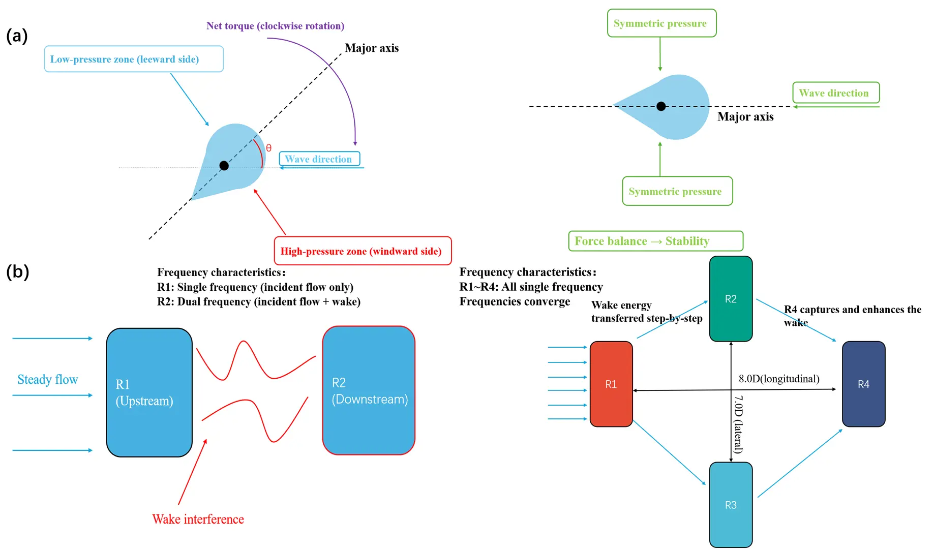
Figure 3. (a) Passive self-alignment mechanism of the sunflower-inspired teardrop platform; (b) Wake-enhanced cooperative mechanism of the fish-school-inspired diamond array.
3.2. Bionic Deformation Enhancement and Low Flow Response Strategies
Waves are often not “intense”. Especially in low-flow environments, many TENGs struggle to start stably. However, traditional structures often struggle to respond stably in low-flow or slightly fluctuating environments, and such issues currently exist in many devices [44]. To improve this situation, researchers began to draw on flexible structural features found in nature. For example, kelp can produce noticeable oscillations under weak water flows, while whale shark gill covers can regulate fluid action through a special curved structure. Although these structural forms differ greatly, the goals of the various works are basically the same: to improve structural responsiveness under weak flow conditions [53,54,55,56,57,58,59,60,61,62,63,64,65,66].
1. Fluid-Structure Coupling Resonance Inspired by Kelp’s Smooth Swing: Kelp achieves large swings with waves through flexible bending, with the core being the fluid-structure coupling effect. When the frequency of the flexible structure approaches the wave frequency, a more pronounced oscillation response can be produced. Inspired by this, Sun and others designed a kelp-like high power density TENG, composed of stacked foliated units, with PTFE spheres rolling and generating electricity under wave excitation [67]. Its basic structure is shown in Figure 4a. A single unit achieves 623.14 V open-circuit voltage and 1.48 μA short-circuit current at 2.5 Hz and 45° swing. The 15-unit integrated K-TENG achieves a power density of 18.77 W/m3, maintaining stable operation for 16 h [67].
2. Flow Enhancement Inspired by the Curved Contour of Whale Shark Gill Cover: For directional water flow scenarios, Zhang J and colleagues were inspired by the respiratory movement of the whale shark gill cover and designed a biomimetic gill cover structure TENG [68]. Its basic structure is shown in Figure 4b. The gill cover closes at the bottom of the waterwheel to increase driving torque, and opens at the top to reduce resistance. The power generation unit uses eight flexible hollow FEP tubes to generate rolling friction. After 1.7 million cycles, performance retention exceeds 95%, while the sliding friction control has dropped below 30%. CFD results show that vortex attachment is more likely to form near the tail edge of the gill cover, thereby increasing the local driving torque. Therefore, the rotation frequency of this structure is about 24.54% higher than that of ordinary waterwheels. The device can operate stably at an ultra-low flow rate of 0.22 m/s [68].
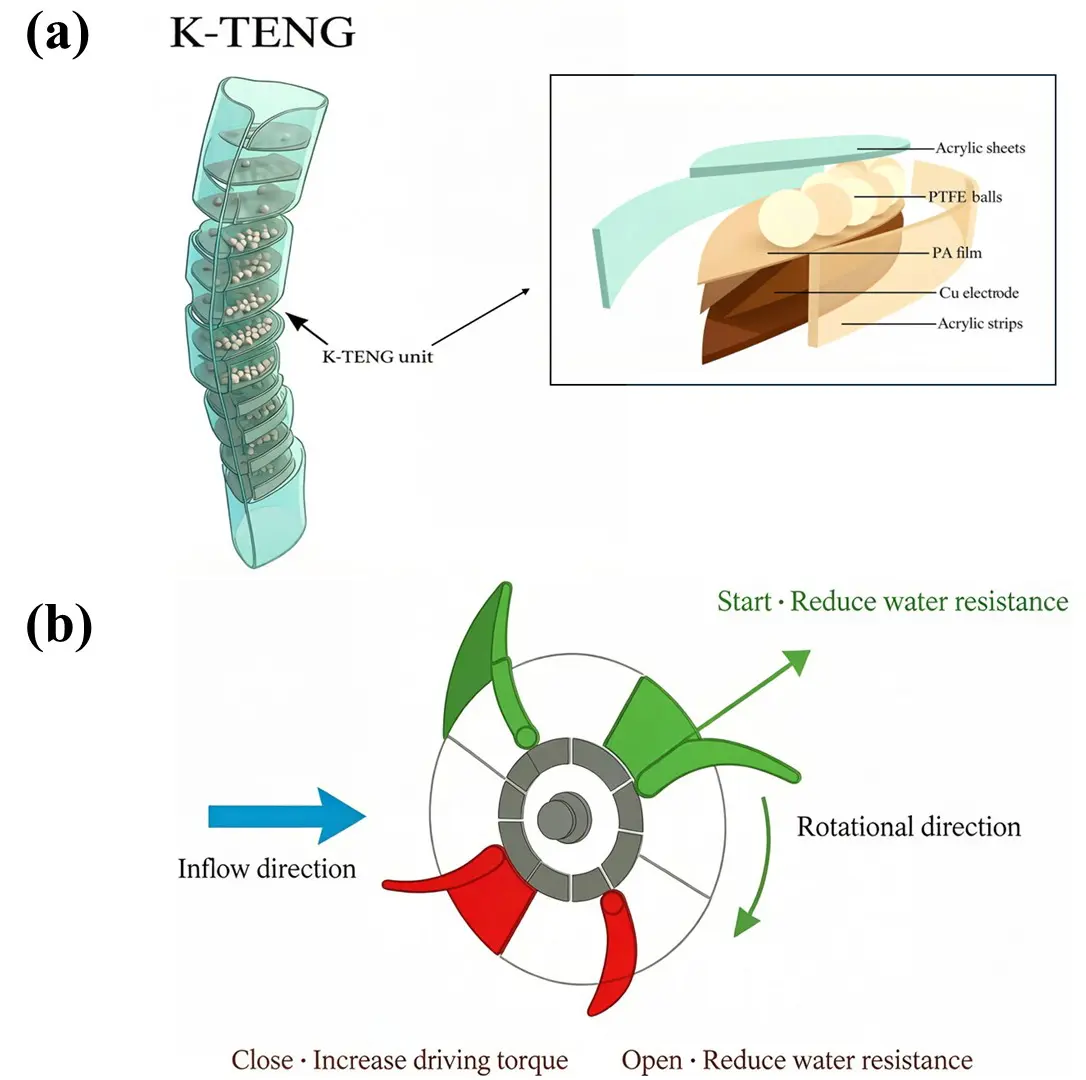
Figure 4. (a) Fluid–structure coupled oscillation mechanism of the kelp-inspired stacked structure; (b) Whale-shark-inspired gill-cover structure and rolling-friction TENG mechanism for low-flow-response energy harvesting.
3. Fluid vibration enhancement inspired by biomimetic fish tail structures: Zhang Y and others designed a bionic fish tail TENG inspired by the swordfish tail fin [69]. Crescent-shaped steel structures are coated with a polyurethane anti-corrosion coating; the rubber on both sides deforms during swings and collides with the coating to generate electricity. CFD simulations confirm that the mimicking fish tail cross-section produces greater vortex effects and pressure differences. After running continuously in water at 2 Hz for 7 days, the output shows almost no attenuation, combining self-powered salinity meter and cathodic protection functions [69].
3.3. Bionic Durability Interface Strategy
Compared with laboratory environments, marine environments often have a more significant impact on the stability of TENG interfaces. High humidity can accelerate charge dissipation, salt spray easily causes material corrosion, and biofouling may cover the friction interface [45]. For marine TENGs, whether interface charges can remain stable over the long term has always been a central issue. Lotus leaves achieve self-cleaning through an air cushion layer, while shark skin suppresses microbial adhesion through micro-grooves—these two structural approaches are not the same. Lotus leaves are more about removing contaminants, whereas shark skin is more about reducing adhesion itself.
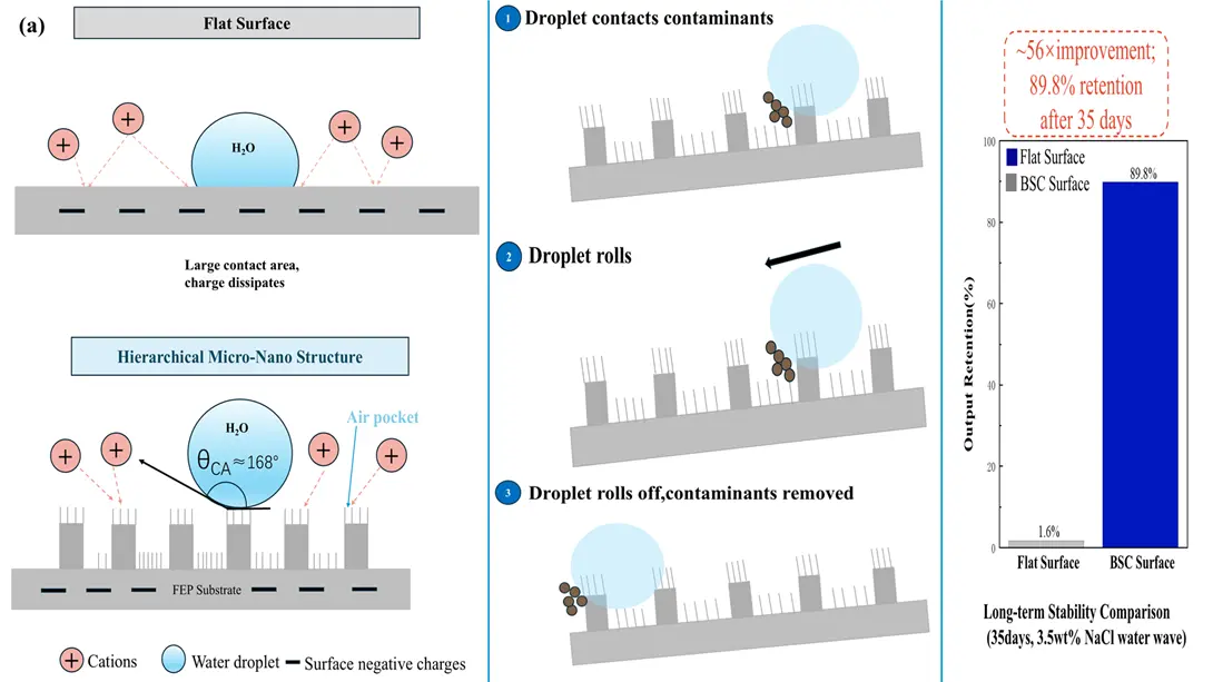
1. Superhydrophobic Self-Cleaning Interface Inspired by the Lotus Leaf Effect: In marine environments, solid-liquid TENGs are easily affected by salt ions and biofouling. Ions in water can weaken the interfacial charge, and microbial attachment may further affect charge transfer efficiency. To address this issue, Zhao et al. [70] were inspired by the surface structure of lotus leaves and constructed hierarchical micro-nano structures on FEP surfaces, as shown in Figure 5a. This structure consists of a micrometer-scale pillar array and surface nanowires, allowing part of the air layer to be retained between the interfaces, thereby reducing the actual contact area. At the same time, the lower surface adhesion also facilitates water droplets rolling off and carrying away contaminants. In saline environments, the reduction in interfacial charge is relatively smaller. Experimental results show that the output of the biomimetic structure in a 3.5 wt% NaCl solution only exhibits a slight decrease, whereas the attenuation on ordinary flat surfaces is more pronounced [70]. During cyclic testing, there is no obvious decay in its output. Based on current results, the micro-nano structure helps mitigate interfacial performance degradation. However, whether this effect can be maintained long-term still requires more data from marine environments.
2. Drag Reduction and Low-Adhesion Interfaces Inspired by Shark Skin Denticle Structures: Unlike the lotus leaf structure, which focuses on “self-cleaning”, the denticle structure on shark skin primarily serves to reduce adhesion tendency. The oriented micro-grooves on its surface can alter the state of the fluid boundary layer and may also make microbial attachment more difficult. Yeh and others [71] replicated similar shark skin microstructures using flexible materials and studied their interfacial behavior during liquid metal contact-separation processes, as shown in Figure 5b. The results showed that the residue phenomenon on microstructured surfaces was significantly reduced, whereas unstructured surfaces were more prone to adhesion and contamination. Although this study mainly targets wearable devices, the interface regulation mechanism it reveals also has certain reference significance for marine TENGs. If future tests can include real marine anti-fouling evaluations, such structures might help improve interfacial stability under long-term operational conditions.
Based on the currently available work, it can be seen that bionic structures can indeed improve the adaptability of marine TENGs to complex sea conditions to a certain extent. Among them, structures inspired by sunflowers, fish schools, and kelp mainly focus on enhancing motion response under wave conditions; structures mimicking whale sharks and fish tails are more commonly used to improve energy harvesting performance under low-flow conditions [48,49,50,51,52,67,68,69]. In terms of interfacial stability, superhydrophobic micro-nano structures and low-adhesion microstructures have also shown certain effects, especially in slowing down fouling and interfacial charge decay [71]. However, many of the current results still mainly come from laboratory conditions. Issues such as long-term operation in real oceans, complex wave coupling, and large-scale array coordination still lack sufficient publicly available data. Some bionic structures also face practical engineering challenges in terms of processing complexity, the lifespan of flexible materials, and subsequent encapsulation. Additionally, a noticeable trend is that in recent years, related research has moved beyond merely improving instantaneous output parameters and has begun to focus more on stable operation under complex environments. From this perspective, bionic design is likely to remain an important direction in the field of marine TENGs.
 |
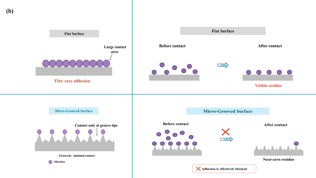 |
Figure 5. (a) Air-pocket formation, self-cleaning behavior, and interface-stabilization mechanism of the lotus-leaf-inspired hierarchical micro–nano structure; (b) Anti-adhesion and low-residue interface mechanism of the shark-skin-inspired micro-grooved topology.
4. Tribodynamic Nanogenerators Based on Flexible Mechanisms
In underwater environments, the magnitude and direction of flow velocity and direction are constantly changing. Mechanical devices relying on propellers and water turbines usually require stable and persistent flow velocity and direction, which cannot effectively collect ocean current energy. To address this, researchers have developed tribo-nanogenerators based on flexible mechanisms. Below are five types of tribo-nanogenerators based on flexible mechanisms, discussing seven aspects: structure, working principle, operating mode, electrical energy output, comparison of the four flexible mechanism-based TENG, environmental adaptation, and performance optimization.
4.1. Underwater Flag-Like Triboelectric Nanogenerator (UF-TENG)/High-Performance High-Efficiency Flag-Like Triboelectric Nanogenerator (UHF-TENG)
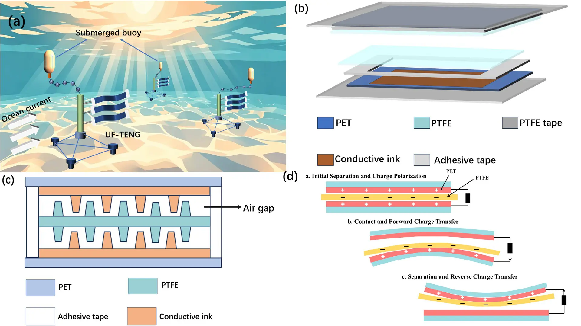
To efficiently capture low-speed ocean current energy, UF-TENG was proposed by Professor Xu Minyi’s team [72]. UF-TENG vibration is enhanced by vortices formed behind cliff bodies, reducing vibration to as low as 0.133 m/s. The key starting speed of the s offers excellent low-speed performance; Xuanhuang and colleagues designed a UHF-TENG that can efficiently capture energy in ultra-low flow rate environments and adapt to different flow speeds and environmental conditions. At a flow speed of 0.02 m/s, the maximum output power under optimal resistance conditions is 20 μW, effectively enabling unmanned underwater monitoring and signal transmission. The main body of the UF-TENG system consists of UF-TENG and an upstream cylindrical structure, as shown in Figure 6a [72]. UF-TENG is made of materials such as polyethylene terephthalate (PET) and polytetrafluoroethylene (PTFE) films covered with conductive ink. Using PTFE waterproof tape, two PET films coated with conductive ink are bonded together with one PTFE film. The air gap caused by the tape and the microstructure of the material both ensure the stable underwater output performance of UF-TENG, as shown in Figure 6b,c [72]. The operating mode is contact separation, with the following working principle, as shown in Figure 6d [72]: (1) After starting the ocean current excitation device, the PTFE film and the conductive ink-coated PET film are periodically separated and contacted. Based on electrostatic induction, PTFE films and conductive ink coatings each generate the same amount of charge. (2) When UF-TENG is excited to vibrate, the PTFE film comes into contact with the conductive ink coating. When the PTFE membrane contacts the lower electrode, all positive charges flow toward that electrode, causing a transient current in the external circuit. (3) Then, the reverse tapping of the PTFE membrane causes electrons to transfer in reverse through the external circuit. COMSOL Multiphysics’ commercial software was used in this paper to verify changes in the electrostatic field distribution of TENG, and the results were consistent with the above analysis.
Based on the theoretical framework of contact-separation mode triboelectric nanogenerators (TENGs), the output voltage is governed by surface charge density, electrode gap distance, and the dielectric characteristics of the materials. In essence, when the two triboelectric layers undergo periodic contact and separation, the resulting variation in inter-electrode capacitance drives induced charges through the external circuit, producing an alternating voltage output. The magnitude of this voltage primarily depends on the surface charge transferred during contact, the separation distance, and the dielectric constant of the intervening medium. In practice, the maximum voltage is further constrained by air breakdown under high electric fields and leakage currents through the dielectric layer [72].
Regarding the power output performance of UF-TENG, Professor Xu Minyi’s team [72] proposed the following influencing factors: eddy current enhancement effect, bending stiffness and aspect ratio, and the distance between electrodes. The eddy current enhancement effect of UF-TENG vibration has been verified in flume experiments. At a flow velocity of 0.461 m/s, the presence of a cylinder increased the UF-TENG output performance significantly by 170%. When the circulation flume parameters are M* = 1590 and L/W = 2, at U = 0.461 m/s (or KB = 0.06 × 10⁴), UF-TENG achieved an output voltage of 14.4 V. Experimental results show that UF-TENG can output higher voltage at lower bending stiffness and/or aspect ratio. Increasing the mass ratio (for example, increasing the mass ratio from 955 to 1590) can achieve a lower critical speed and higher output performance. The vibration amplitude is proportional to the flow velocity, and increasing the vibration amplitude can achieve a larger contact area of the triboelectric layer. When the flow velocity increases from 0.133 m/s to 0.461 m/s, the output current can reach 1.43 μA. Experimental results indicate that the vibration frequency of UF-TENG increases with the flow velocity, and the output current increases accordingly. According to the formula, increasing the distance between the two electrodes (g) can optimize the UF-TENG performance. However, increasing the thickness of UF-TENG (d0) will lead to an increase in bending stiffness, which causes a sharp increase in critical speed (increasing g from 0.11 mm to 0.23 mm results in a drastic increase in UF-TENG’s critical speed), making this method unreasonable. Connecting six UF-TENG units in parallel results in a total output power that is six times that of a single UF-TENG unit, with the specific circuit diagram shown in Figure 6e.
 |
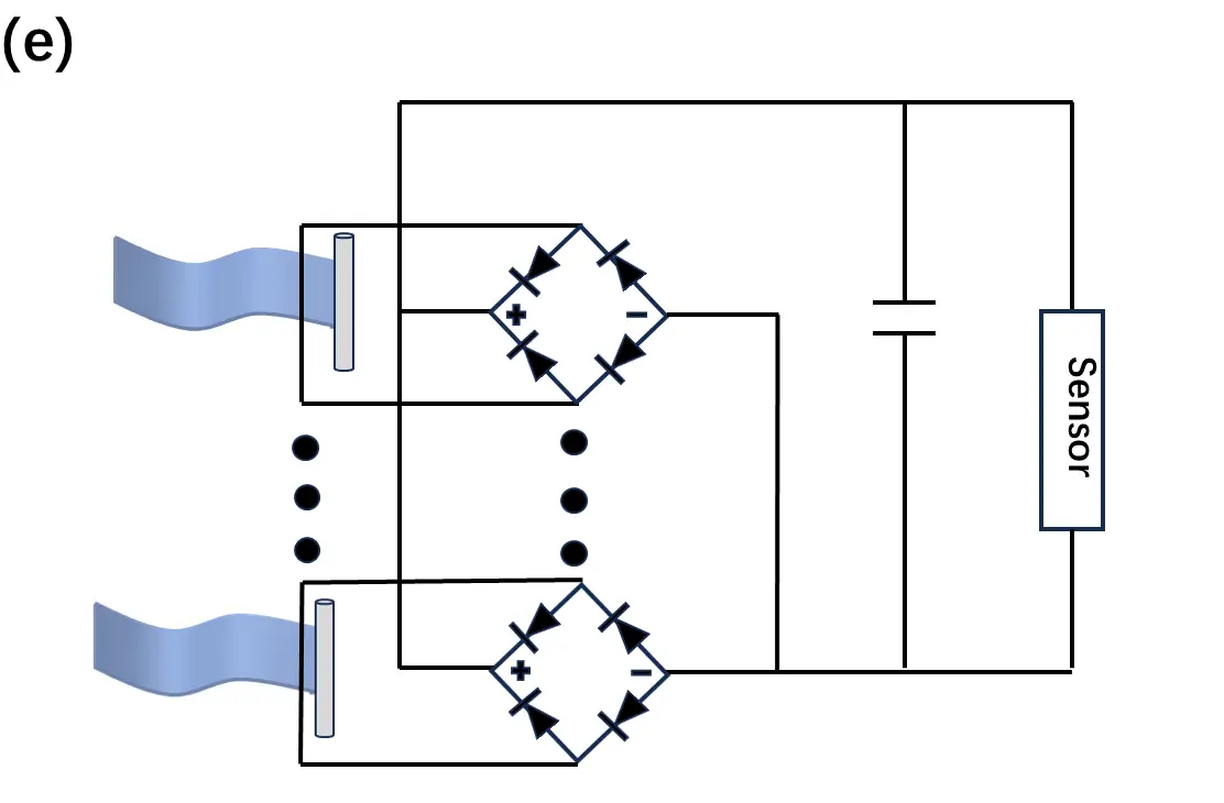 |
Figure 6. (a) Schematic drawing of the UF-TENG and its applications; (b) The UF-TENG internal structure; (c) Schematic illustration of the contacting surface; (d) The principle of the UF-TENG; (e) ematic diagram of six UF-TENG units and working circuit to power the sensor.
The UHF-TENG is composed of two mirror-symmetrical upper and lower parts, each containing a pair of triboelectric pairs. A self-polarized BaTiO3/PVDF composite film serves as the negative material, with a piece of copper foil in the middle acting as the common floating electrode and positive-side material. The back electrode is a silver ink electrode. PFPE oil between the triboelectric pairs prevents electrostatic breakdown and improves the lubrication of the triboelectric pairs. All electrodes are connected with wires and sealed with waterproof PTFE tape and silicone, as shown in Figure 7a [73]. The working mode is a contact-separation type, and the working principle is as follows, as shown in Figure 7b [73]: (1) Initially, the device is flat and undeformed, and the PFPE oil prevents contact between the BaTiO3/PVDF film and the copper electrode. (2) After starting the ocean current excitation device, due to the triboelectric effect, when the device bends, the BaTiO3/PVDF film and the copper electrode generate negative and positive charges, respectively. (3) When the composite film contacts the copper electrode, the oil layer is squeezed out, with the composite film becoming negatively charged and the copper electrode positively charged. The change in the triboelectric gap causes charge movement, generating current. (4) When the composite film contacts the copper electrode, all positive charges produce a transient current. (5) When returning to the flat, the PFPE oil fills the space between the BaTiO3/PVDF film and the copper electrode again, causing a change in capacitance. Due to the electrostatic induction effect, part of the positive charge flows through the external circuit to the silver electrode, forming a current. (6) As the device bends again to produce a reverse capacitance change, part of the positive charge flows back to the copper electrode, forming a reverse current. (7) Then, with periodic back-and-forth bending, the charges generated by the triboelectric effect move back and forth as alternating current.
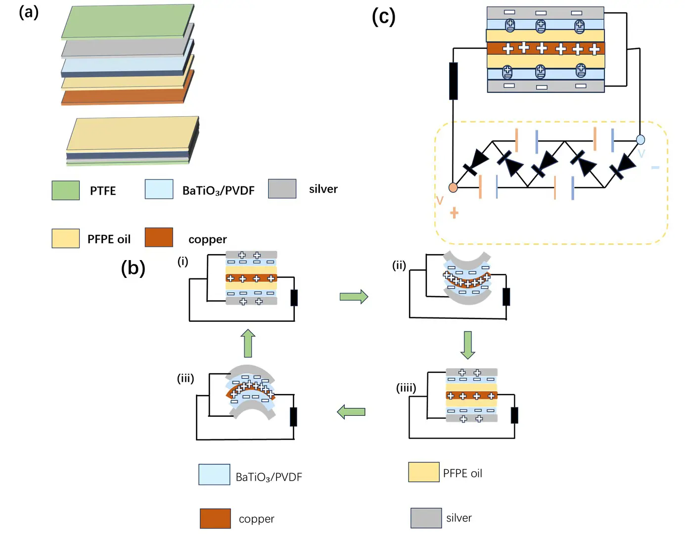
Figure 7. (a) The UHF-TENG internal structure; (b) the principle of the UF-TENG; (c) ircuit diagram of the connection between UHF-TENG and external VMC.
The power output performance of UHF-TENG is mainly optimized in terms of BaTiO3 content, mechanical input parameters (different movement ranges and frequencies driven by linear motors), different electrical loads, VMC amplifier circuits, and hydrostatic resistance [73]. Open-circuit voltage (V), short-circuit current (I), and short-circuit transfer charge (Q) all reach their maximum values at 5 wt% BaTiO3 (V = 28.5 ± 0.95 V, I = 4.06 ± 0.28 μA, Q = 29.3 ± 0.83 nC). The power output performance of UHF-TENG is proportional to the motion distance and positively correlated with the frequency of the linear motor. As the movement range increases to 80 mm, the open-circuit voltage (V), short-circuit current (I), and short-circuit transfer charge (Q) rise to 4.05 ± 0.24 μA, 30 ± 1.9 V, and 32 ± 0.8 nC, respectively. As frequency increases, the open-circuit voltage (V), short-circuit current (I), and short-circuit transfer charge (Q) steadily rise to their maximum values of 4 ± 0.5 microampere, 28 ± 1.6 volts, and 30 ± 2.1 nanometers, respectively. In experiments simulating real marine environments under high hydrostatic pressure, even when the compression pressure is below 30 MPa (equivalent to a depth of 3000 m underwater), UHF-TENG’s power output performance is maintained (short-circuit current at 8.0 ± 0.3 microamperes, open-circuit voltage at 119 ± 1.5 volts). Under compression tests under different high hydrostatic pressure and hydrostatic resistance times, the power output performance of UHF-TENG is not significantly affected [73]. This experiment effectively addressed Wang Yan and colleagues’ concerns about the impact of output performance under high water pressure and their expectations for developing UF-TENG capable of working in deep water. Ircuit diagram is shown in Figure 7c.
4.2. Bionic Seaweed-Like Triboelectric Nanogenerator (S-TENG)/Flexible Seaweed-Like Triboelectric Nanogenerator (SW-TENG)/Seaweed Structure-Like Triboelectric Nanogenerator (SS-TENG)
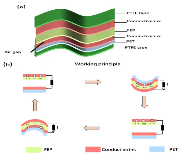
Wang et al. [74] believe that traditional TENGs mainly collect energy from surface waves, and it is very necessary to design a TENG that can be applied underwater and adapt to broader sea areas. Therefore, they developed a bionic seaweed-like triboelectric nanogenerator (S-TENG). The mechanical structure of traditional wave energy collection devices based on triboelectric nanogenerators is too complex, greatly increasing the difficulty of manufacturing and maintenance. Wang He [74] designed a flexible seaweed-like triboelectric nanogenerator (SW-TENG) with the aim of reducing the use of complex mechanical transmission structures and improving energy conversion efficiency. The S-TENG system consists of fluorinated ethylene propylene (FEP) material coated with conductive ink, polyethylene terephthalate (PET) coated with conductive ink, and two polytetrafluoroethylene (PTFE) films, as shown in Figure 8a [74]. The PTFE films seal the conductive ink, FEP material, and PET, preventing contact with seawater and loss of surface charge. The working principle is as follows, as shown in Figure 8b [74]: (1) After starting the ocean current excitation device, the FEP film periodically contacts and separates from the PET film. (2) Due to the electrostatic induction effect, after fully contacting the PET film coated with conductive ink, the FEP film acquires negative charges, and the conductive ink on the PET film acquires an equal amount of positive charges. (3) After the S-TENG bends, electrons flow through the external circuit from the FEP-connected electrode to the PET-connected electrode. (4) After the FEP film separates from the conductive ink, the positive charges flow back.
Wang et al. [74] studied the power output of S-TENG as a function of linear motor movement amplitude, vibration frequency, load resistance, charging capacitor, salinity, and underwater pressure. Increasing the amplitude of S-TENG (achieving a maximum output voltage of 12.2 V through a transfer charge of 22.4 nC) and frequency (at a maximum wave frequency of 1.25 Hz, an open-circuit voltage of 24.8 V and a transfer charge of 43.2 nC) can greatly enhance the output current. The current and power density of S-TENG under different load resistors (under a 20 MΩ matched load resistor, the peak output power of S-TENG reaches a maximum of 10.56 μW). S-TENG demonstrates excellent charging capability under different capacitor conditions [74]. Although salinity has no significant effect on output performance, experiments testing output performance at different salinity levels remain very important, as they make the experiment more complete and rigorous. The hydrostatic pressure experiment involves rigidly mounting different mass blocks onto the S-TENG, increasing its surface pressure (from 10 kPa to 100 kPa), and using another mass block to strike the lower mass block and the S-TENG from an equal height. The air gap in S-TENG gradually compresses as water pressure increases, and the output current gradually decreases, but after reaching a certain water pressure, the output current remains basically unchanged. Experimental results show that S-TENG can be used to collect wave energy under different water pressure conditions [74]. Researchers also enhanced power output by paralleling the two S-TENGs, as the distance between the two S-TENGs affected the vibration of each S-TENG. Ultimately, experimental studies determined that the distance between the two S-TENGs was maintained at 90 mm [74]. Researchers developed a system integrating S-TENG to study the increase in total output (as the number of S-TENG cells increased from 1 to 9, the output voltage of parallel S-TENG increased from 24.8 to 120.6 V, while the output current increased from 2.6 to 8.7 μA. Experiments show that paralleling more cells can indeed achieve higher power [74].
SW-TENG is a small TENG based on a buoy-fixed design, mainly aimed at practical applications on the sea surface. The main body consists of three parts: the TENG power generation unit, the fixing device, and the buoyancy device. The buoyancy device, driven by ocean excitation, moves the SW-TENG up and down. A connecting rod links the buoy and the fixed plate into a whole, and clamps are used to install the slot onto the fixed plate to prevent the TENG power generation unit from being swept away by waves [75]. The structure and working principle of the TENG power generation unit are basically the same as those of S-TENG. Wang He studied energy output in seven aspects: amplitude, frequency, salinity, device size, Young’s modulus, as well as the parallel spacing and number of devices [75]. In particular, regarding the influence of Young’s modulus on SW-TENG output, Wang [75] selected materials with Young’s moduli of 2 GPa, 3.5 GPa, and 8 GPa. Under conditions of 100 mm amplitude and 1 Hz frequency, the maximum open-circuit voltage was measured as 26.5 V, 18.5 V, and 4.8 V, respectively; the maximum short-circuit current was 2.2 μA, 1.6 μA, and 0.8 μA, respectively; and the maximum transferred charge was 42 nC, 18.9 nC, and 12.5 nC. An increase in Young’s modulus leads to a decrease in energy output. The effects of parallel spacing and number were also studied: parallel spacing has little impact on energy output, while increasing the number of parallel units can improve the maximum short-circuit current and the maximum transferred charge [75].
4.3. Paired Triboelectric Nanogenerator (P-TENG)
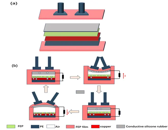
To address excessive internal pressure that affects structural movement during the harvesting of mechanical energy from unidirectional water flow, Deng et al. [76] proposed a paired triboelectric nanogenerator. The P-TENG mainly adopts a novel gas chamber exchange structure and a rigid-flexible coupled deformation mechanism, with interconnected internal cavities that allow free gas exchange and adapt to high water pressure, as shown in Figure 9a [76]. This device is small in size and lightweight, and through array deployment, it can implement a structured triboelectric surface device that can be attached to different structures to harvest wave energy from different directions and forms, meeting underwater power requirements. The working principle is shown in Figure 9b [76].
TENG forms a structured triboelectric surface (STS) through large-scale integration. The STS with a main layer thickness of 4.5 mm achieves a high-frequency output of up to 57 Hz and a high cumulative charge output of 1.59 μC/s, with a power density more than 100 times higher than existing wave energy TENG devices [76].
4.4. Flexible TENG-Hydrogel Device with Adhesive Surface Based on Honeycomb-Structured PA Hydrogel
Inspired by the strong adhesion of octopus tentacles, Qian Yu [77] designed a flexible triboelectric nanogenerator based on honeycomb-structured PA hydrogel, which can quickly, reversibly, and firmly adhere to the side of boats or lifebuoys in water to harvest wave energy. The honeycomb-structured PA hydrogel-based flexible triboelectric nanogenerator consists of a flexible hydrogel and a flexible TENG (Ecoflex film and AgNWs/1PVA (PDMS/CB) sensing electrode film) [77]. The TENG-Hydrogel hybrid device forms an energy harvesting unit through a PA gel/PDMS hybrid with a planar TENG. The working mode of the TENG-Hydrogel composite device is a single-electrode mode. The working principle of the device is as follows, as shown in Figure 10 [77]: The double layer of water determines that the water on the surface of the film only acts to shield the triboelectric charges. In the steady state, the two connected electrodes form an equipotential, and the charges should be evenly distributed on both electrodes. (1) When the water level rises, electrode 1 enters the water, and electrons flow from electrode 2 to electrode 1. (2) As the water level continues to rise, electrode 2 is submerged, and electrons flow back from electrode 1. (3) When the entire device is fully submerged, symmetric shielding of the triboelectric charges is achieved, no electron transfer occurs between the two electrodes, and the potential difference is zero. (4) When the water waves fall, electrode 2 is lifted out of the water, and electrons flow from electrode 2 to electrode 1, after which the cycle repeats periodically. Qian Yu tested the electrical energy output of the TENG-Hydrogel hybrid device under different water levels, different electrode aspect ratios, and different water wave fluctuation frequencies. The experimental results show that at different water levels, the TENG-Hydrogel hybrid device achieves the best electrical energy output within the gap range between the upper and lower strip electrodes; the output is optimal when the aspect ratio is 2.0. When the matched resistance is 4.04 MΩ, the maximum peak power of the TENG-Hydrogel device is 6.3 μW [77].
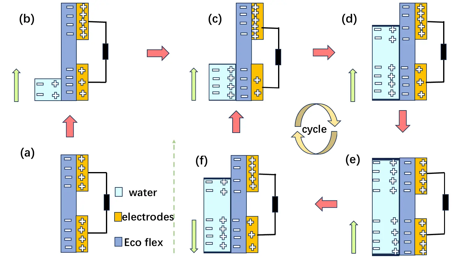
Figure 10. The principle of the TENG-Hydrogel. (a) Schematic diagram of the TENG-Hydrogel hybrid device structure, showing the PA hydrogel, Ecoflex film, AgNWs/PVA (or PDMS/CB) sensing electrode, and water level. The red arrows indicate electron flow steps; the green arrows indicate water wave movement. (b) Schematic diagram of the working cycle of the device under water wave excitation. (c) When the water level rises and electrode 1 enters the water, electrons flow from electrode 2 to electrode 1. (d) As the water level continues to rise and electrode 2 is submerged, electrons flow back from electrode 1 to electrode 2. (e) When the entire device is fully submerged, symmetric shielding of the triboelectric charges is achieved, and no electron transfer occurs between the two electrodes. (f) When the water wave falls and electrode 2 is lifted out of the water, electrons flow from electrode 2 to electrode 1, completing the cycle.
4.5. Composite Wave Energy Harvester Based on Multi-PC Array and Halbach Array
To improve wave energy acquisition efficiency and device space utilization, and to combine the advantages of non-inertial direct drive, Jing [78] designed a high-density composite wave energy harvester with high-density energy output. The multi-PC fuzz array material uses a flexible mechanism to greatly enhance durability, and the Halbach magnet array significantly increases electrical energy output by increasing the friction surface and enhancing the asymmetric distribution of the magnetic field. The main design concept of this composite wave energy harvester is to directly drive the non-inertial type, allowing the upper drive plate to directly contact and be driven by the wave, avoiding multiple energy conversions and losses, and significantly improving energy harvesting efficiency. This system is essentially a combination of TENG and EMG units, consisting of a housing structure, drive plate, and semicircular grille section. The housing consists of four semicircular shapes of equal area, with two circular through-holes symmetrically. The sides are semi-cylindrical column shells, and the top is a rectangular through-groove cover plate. Magnetic arrays embedded inside the sector-shaped structure on both sides and copper coils embedded on the upper and lower bottom surfaces are constructed. The upper half of the rectangular drive plate is on the outside, while the lower half is inside the shell. The lower end of the drive plate is fan-shaped with a fan-shaped rabbit hair of the same area attached as the TENG rotor; The interior of the semi-cylindrical shell is fixed with evenly spaced semicircular grates. The surfaces on both sides of the grate are covered with copper electrodes and FEP film, forming the TENG stator. The drive plate is fixed to the inner wall of the upper and lower bottom surfaces of the housing via bearings and bearing rods, as shown in Figure 11a [78].
The working mode is an independent layered type, and the working principle is as follows, as shown in Figure 11b [78]: The FEP film is in good indirect contact with the sector-shaped PC bristle brush. According to electrostatic induction, the surface of the PC bristles carries a positive charge, and the surface of the FEP film carries a negative charge. According to the principle of charge conservation, the amount of induced electrostatic charge on both is equal. (1) Initially, the PC bristles rotate counterclockwise from above the left electrode to above the right electrode. To balance the positive charge on the surface of the PC bristles, electrons move from the left electrode to the right electrode through the external circuit. The negative charge on the left electrode decreases until charge balance is achieved. (2) As the counterclockwise rotation continues, this process cycles periodically, generating an AC output.
Performance optimization was carried out in terms of the friction layer combination of the TENG unit, friction layer thickness, PC pile height, spacing between the EMG unit coil and Halbach array, series-parallel connection mode of TENG and EMG units, and driving frequency. The final results show that selecting the TENG unit with a PC-FEP-Cu composite friction layer structure, FEP friction layer thickness of 80 μm, PC pile height of 8 mm, EMG unit coil to Halbach array spacing of 5 mm, parallel connection of TENG and EMG units, and a driving frequency of 1 Hz yields the optimal electric energy output for the hybrid wave energy harvesting. When the optimal load resistance of the TENG and EMG units is 1 GΩ and 150 Ω, respectively, the maximum peak power reaches 5.80 mW and 8.22 mW.
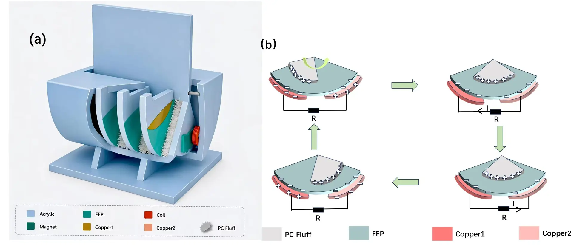
Figure 11. (a) Schematic drawing of the composite wave energy collector; (b) the principle of the composite wave energy collector.
4.6. Summary
4.6.1. Material Selection of Flexible Mechanisms
Table 2 shows the reasons about selection of flexible materials.
Table 2. Selection of flexible materials.
|
TENG |
Material |
Reason |
|---|---|---|
|
PET substrate, PTFE film, conductive ink |
Utilizes the excellent bending performance of thin film materials, allowing good periodic deformation with waves |
|
|
FEP film, PET film, PTFE sealing film |
Fully flexible thin film structure, better adapting to waves of different frequencies and amplitudes |
|
|
TENG-Hydrogel [77] |
PA hydrogel, Ecoflex film, AgNWs/1PVA electrode |
Introduces hydrogel as an adhesive layer, using its high water content and flexibility to achieve reversible underwater adhesion |
|
Composite Wave Energy Harvester [78] |
PC bristles (flexible brush), FEP film |
Bristles serve as a flexible friction layer, greatly reducing wear |
4.6.2. Structural Design of Flexible Mechanisms
1. Bionic Flexible Form: S-TENG [74]/SW-TENG [75]: By observing common seagrass structures, a flexible bionic structure is designed to capture wave energy by converting it into electrical energy through overall bending deformation, rather than relying on the relative motion of rigid structures.
2. Rigid-Flexible Coupled Deformation Mechanism: P-TENG [76]: Through a rigid-flexible coupled deformation mechanism (internal cavity interconnection with gas bag exchange structure), the encapsulated device can balance internal and external pressure through flexible deformation under deep-sea conditions, without hindering structural movement.
3. Flexible Contact Interface: Composite Wave Energy Harvester [78]: A PC array is used as the rotor friction layer of the TENG. The fluff is a typical flexible structure; its contact with the FEP film is point-line contact. Compared to rigid plane contact, this results in lower friction, less wear, and better contact uniformity.
4. Interface Lubrication of Flexible Mechanisms: UHF-TENG [73]: PFPE oil (perfluoropolyether oil) is filled between the BaTiO3/PVDF composite film and the copper electrode. In addition to preventing electrostatic breakdown, the oil layer can act as a flexible liquid replacing the solid contact interface, greatly reducing friction and wear [79,80,81,82,83,84,85,86,87,88,89,90,91,92].
5. Performance and Applications
Chapter 3 discusses, respectively, improvements in bionic strategies such as directional adaptability, low-flow-velocity response, and interface durability that enhance the wave energy harvesting performance of TENG. Chapter 4 introduces, respectively, five types of flexible-mechanism-based TENGs: UF-TENG/UHF-TENG, S-TENG/SW-TENG, P-TENG, TENG-Hydrogel, and composite wave energy harvesters, exploring their material selection and structural design from the perspective of flexibility. However, the performance improvement of a single structure cannot fully reflect its engineering application value; a comprehensive analysis is also needed, considering output capacity, startup conditions, and long-term stability. Hu et al. (2026) [93], in a bibliometric analysis of 567 TENG wave energy harvesting papers from 2012 to 2024, pointed out that this field has moved from early proof-of-concept to performance optimization and system integration stages, with related research beginning to focus more on the combination of materials, structural design, output management, and practical marine applications. Hao et al. (2025) [94] emphasized that the overall performance of TENG wave energy harvesting systems depends on the collaborative optimization of PTO structure, power generation units, management circuits, and marine applications. This chapter, combining performance data and application cases, conducts a comparative analysis of the startup characteristics of different bionic flexible strategies and their actual application performance—particularly the arrayed real-sea verification reported by Xi et al. (2025) [95]—demonstrating the power supply potential of bionic TENGs in real marine scenarios and providing a data basis for the discussion of technical bottlenecks in Chapter 6 and the outlook for future directions in Chapter 7.
5.1. Key Performance Comparison of Biomimetic Strategies
In order to more intuitively compare the performance differences of different biomimetic strategies, this paper organizes and compares the key data involved in Chapter 3.
5.1.1. Output Performance Comparison
The TENG selection strategies based on biomimetic and flexible mechanisms differ significantly, mainly reflected in power density, open-circuit voltage, short-circuit current, and so on. Table 3 and Table 4 show a comparison of the output Performance of bionic TENGs and flexible TENGs.
Table 3. Comparison of output performance of bionic TENGs.
|
Bionic Strategy |
Structure Features |
Power Density |
Open-Circuit Voltage |
Short-Circuit Current |
References |
|---|---|---|---|---|---|
|
Sunflower Self-alignment |
Butterfly Stack Self-aligning Platform |
Output Gain 548% |
146.52 V |
132.97 μA |
[48] |
|
Fish School Rhombic Formation |
Four-unit Rhombic Array |
0.2 mW/m3 |
172.4 V (R4) |
— |
[49] |
|
Kelp Stack |
15-unit Parallel Connection |
18.77 W/m3 |
623.14 V |
1.48 μA |
[67] |
|
Bionic Jellyfish Buoy |
Hemispherical Buoy, Umbrella Membrane |
3 times higher than a traditional buoy |
— |
37 μA |
[50] |
|
Origami TENG |
Three-layer Accordion Style |
5.39 mW/m2 |
21 V |
2.8 μA |
[51] |
|
Flapping Wing Hybrid |
Piezoelectric-Friction Hybrid |
5.24 μW/cm3 |
— |
— |
[52] |
Table 4. Comparison of output performance of flexible TENGs.
|
Flexible Mechanism |
Features |
Power Density |
Open-Circuit Voltage |
Short-Circuit Current |
References |
|---|---|---|---|---|---|
|
UF-TENG |
Vortex enhancement effect, flag-like structure, at flow velocities as low as 0.133 m/s |
— |
12.8 V |
0.81 µA |
[72] |
|
UHF-TENG |
Vortex enhancement effect, flag-like structure, BaTiO3/PVDF composite film, at flow velocities as low as 0.02 m/s |
Maximum output power 20 μW |
44.5 ± 5.3 V |
3.2 ± 0.7 μA |
[73] |
|
S-TENG |
Seagrass-like structure |
Maximum peak power 10.56 μW |
24.8 V |
2.6 μA |
[74] |
|
SW-TENG |
Seagrass-like structure |
18.77 W/m3 |
26 V |
2.2 μA |
[75] |
|
TENG-Hydrogel |
Octopus tentacle-inspired structure, PA hydrogel, Ecoflex film, AgNWs/1PVA electrode |
Maximum peak power 6.3 μW |
25 V |
1.6 μA |
[77] |
|
Composite Wave Energy Harvester |
PC bristles (flexible brush) |
Maximum peak power 5.80 mW |
— |
— |
[78] |
From Table 3 and Figure 12, it can be seen that the kelp-stacked TENG leads with a power density of 18.77 W/m3 [67], the sunflower self-aligning platform demonstrates significant directional adaptation benefits with a 548% output gain [48], and the fish school diamond formation achieves an array output of 0.2 mW/m3 at low flow speeds [49]. From the chart, it can be seen that different bionic structures have varying advantages in output capacity, with quite significant differences; from Table 4, it can be seen that at a flow speed as low as 0.02 m/s, the UHF-TENG can reach a maximum output power of 20 μW, an open-circuit voltage of 44.5 ± 5.3 V, and a short-circuit current of 0.81 µA [73]. Compared with other flexible TENGs, it has better electrical output. However, since the test conditions for various flexible TENGs differ, this table is for reference only.
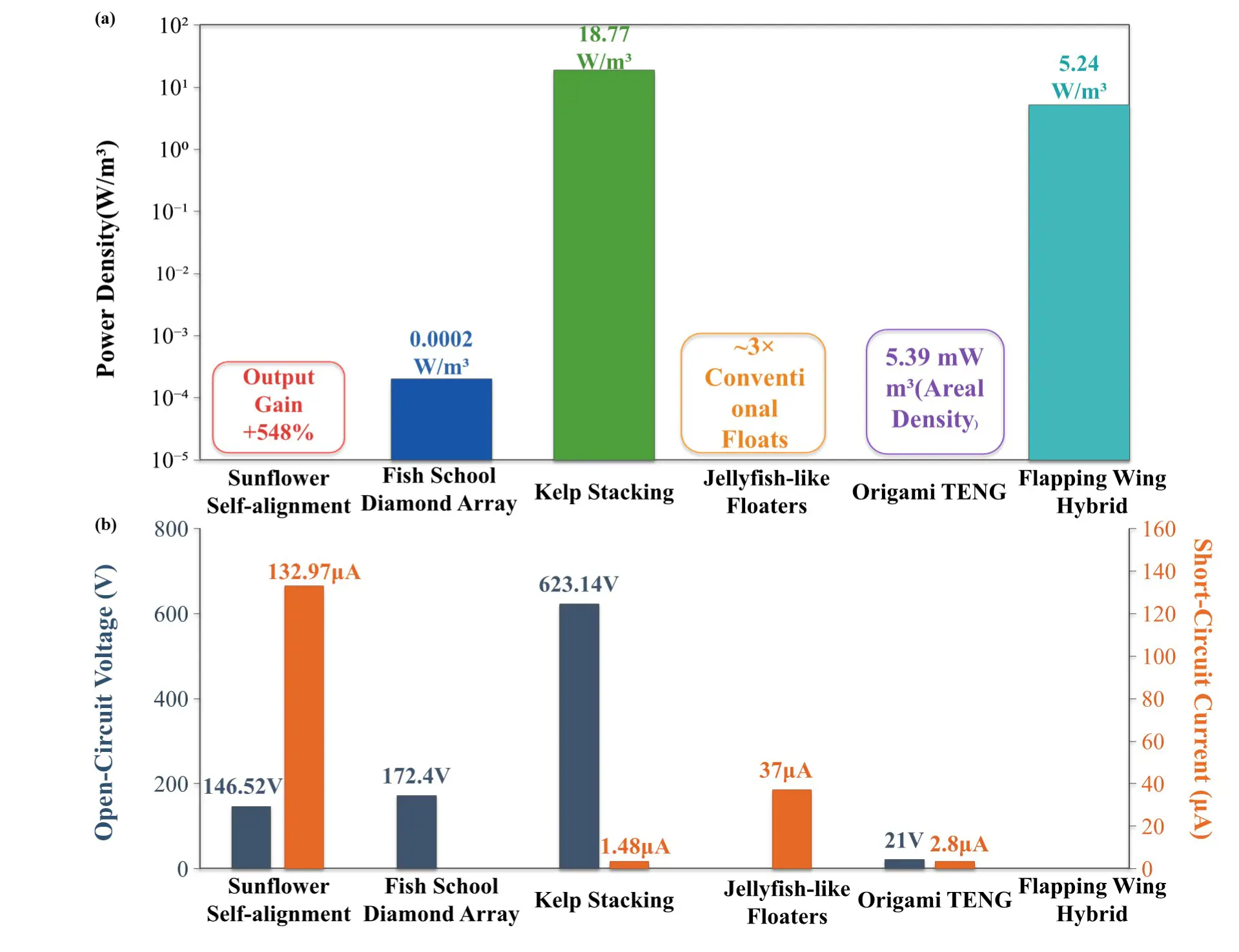
Figure 12. (a) Power density and output gain comparison using logarithmic coordinates; (b) Open-circuit voltage and short-circuit current comparison using dual y-axes. Data summarized from Refs.
5.1.2. Startup Threshold Comparison
To address the challenges of low flow velocity and slight excitation, different bionic flexible strategies reduce the effective operating threshold of TENG through differentiated physical mechanisms. Table 5 summarizes the startup thresholds of the main bionic strategies; Table 6 summarizes the startup thresholds of the main flexible strategies.
Table 5. Comparison of startup thresholds for bionic TENGs.
|
Bionic Strategy |
Minimum Startup Flow Rate |
Physical Mechanism |
References |
|---|---|---|---|
|
sBionic Whale Shark Gill Cover |
0.22 m/s |
Flow Around Curved Surface, Rolling Friction |
[68] |
|
Kelp Bionic |
0.5 Hz (Lower Limit of Broadband) |
Fluid-Structure Coupling Resonance |
[67] |
|
Fish School Diamond Formation |
0.35 m/s |
Vortex-Induced Vibration, Wake Energy Capture |
[49] |
|
Fish Tail Bionic |
2 Hz |
Flow-Induced Vibration, Tail Swing Enhancement |
[69] |
Table 6. Activation thresholds of major biomimetic strategies.
|
Strategy |
Minimum Activation Flow Rate/Frequency |
Physical Mechanism |
References |
|---|---|---|---|
|
UF-TENG |
0.133 m/s |
Flag-shaped structure; Kármán vortex street effect |
[72] |
|
UHF-TENG |
0.02 m/s (ultra-low flow rat) |
BaTiO3/PVDF ultra-fast self-polarization; flag-shaped structure; Kármán vortex street effect |
[73] |
|
S-TENG |
0.9 Hz |
Biomimetic flexible seagrass structure; good adaptation to low frequency |
[74] |
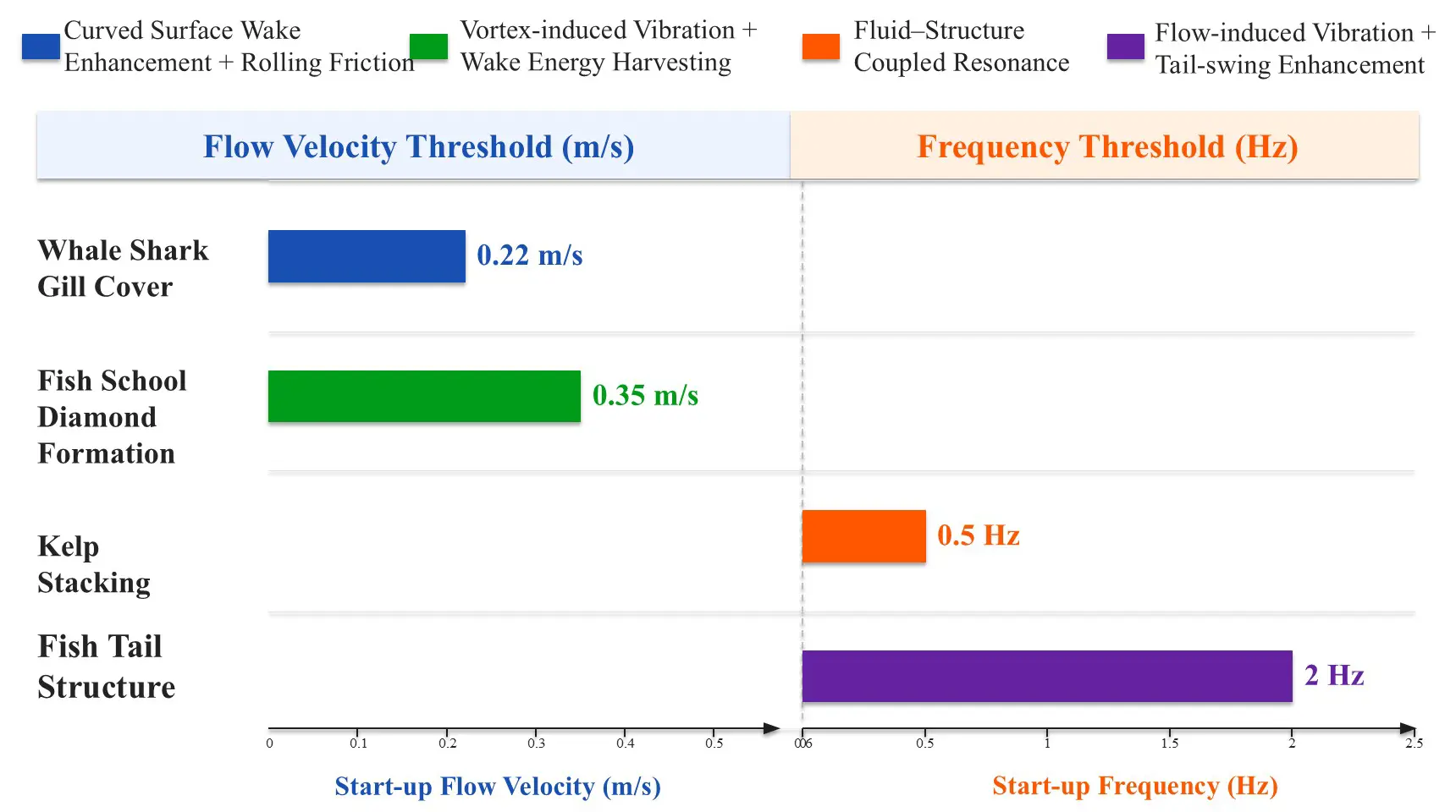
As shown in Figure 13. The whale shark gill-inspired TENG achieves a low startup flow velocity of 0.22 m/s, making it the scheme with the lowest response threshold in the strategy described in Chapter 3 [68]. The kelp-inspired TENG’s broadband response characteristics allow it to effectively harvest energy in the 0.5–4.5 Hz range [93]. These two strategies represent two complementary low-flow adaptation pathways: “lowering the absolute threshold” and “broadening the effective frequency band”. The UHF-TENG achieves the lowest response threshold among the strategies described in Chapter 4, at 0.02 m/s (ultra-low flow velocity). The UHF-TENG can achieve high output under ultra-slow water flow, adapt to different flow environments at high static water pressure, power various applications (sensors and electronic devices), and provide multiple solutions [67].
5.1.3. Durability Comparison
For environmental durability challenges, Table 7 summarizes durability retention data for the main biomimetic strategies; Table 8 summarizes durability retention data for the main flexible strategies.
Table 7. Comparative durability of bionic TENG.
|
Bionic Strategy |
Test Duration/Number of Cycles |
Performance Retention |
Protective Mechanism |
References |
|---|---|---|---|---|
|
Whale Shark Gill Cover Rolling Friction |
1.7 million cycles |
>95% |
Rolling replaces sliding |
[68] |
|
Fish Tail TENG |
Continuous operation in water for 7 days |
Almost no attenuation |
Anti-corrosion coating, PE sealing |
[69] |
|
Lotus Leaf Superhydrophobic |
35 days (about 3.78 million cycles) |
89.8% |
Multi-level micro-nano air cushion layer, self-cleaning |
[70] |
|
Kelp Stacking |
Continuous operation for 16 h |
No noticeable attenuation |
Silicone film waterproof sealing |
[67] |
Rolling friction and surface protection are the two main pathways to improve the durability of TENGs. Whale shark gill cover TENG replaces sliding with rolling, maintaining over 95% after 1.7 million cycles [68]; lotus leaf superhydrophobic TENG achieves self-cleaning and long-lasting charge retention through multi-level micro-nano air cushion layers, with the output maintaining 89.8% after 35 days of continuous testing [68]. It is noteworthy that some TENGs have not undergone durability testing, and the testing standards are not uniform; current durability tests are conducted under single-factor or simplified conditions, and long-term service data under multi-factor coupled degradation conditions are still lacking.
5.2. Application Cases of Bionic Flexible TENG
Hu et al. (2026) [93] classified the marine application scenarios of TENGs into four categories based on space: coastal areas, sea surface areas, ocean water bodies, and deep-sea geological environments. Hao et al. (2025) [94] summarized applications into three major areas: distributed network energy harvesting, self-powered sensing, and marine buoys. The following explains several typical application scenarios based on existing research [96,97,98,99,100,101,102,103,104].
1. Self-powered Ocean Environmental Monitoring: Ocean environmental monitoring is one of the most mature application areas of bionic TENGs. The sunflower self-aligning platform BS-TENG provided power to calculators and watches during real-sea tests in the Beibu Gulf, verifying the self-aligning platform’s energy harvesting capability under real wave conditions [48]. The jellyfish-inspired TENG successfully powered water quality sensors and warning lights, and the power management circuit amplified the short-circuit current 560 times to 12 mA, achieving closed-loop conversion from wave energy to sensor signals [50]. Lotus leaf BSC-TENG achieved an average power density of 306 W/m3 under 3.5 wt% NaCl water waves and, after energy storage, powered a wireless sensor module, with a single charge cycle taking less than 24 min [70]. UHF-TENG can power unmanned underwater monitoring nodes and wireless signal transmission modules in weak deep-sea currents (flow speed as low as 0.02 m/s): at an ultra-low flow rate of 0.02 m/s, UHF-TENG can output 44.5 V open-circuit voltage and 3.2 μA short-circuit current, with a maximum output power of 20 μW, sufficient to drive low-power underwater sensors (such as temperature, salinity, depth sensors, etc.) [73]. UF-TENG can be applied to the surfaces of autonomous underwater vehicles (AUVs) and near marine farms for marine current energy harvesting. Experiments show that at a flow rate of 0.461 m/s, it can output 14.4 V voltage and 1.43 μA current [72], providing supplementary power for sensors mounted on AUVs, such as accelerometers and gyroscopes, or deployed around aquaculture nets, using captured marine current energy to drive wireless water flow velocity sensors for real-time monitoring of water exchange.
2. Array Deployment and Practical Sea Verification: Array deployment is considered one of the key directions for TENG to achieve practical marine applications. Xi et al. (2025) [95] developed a four-unit R-TENG buoy array using a ternary medium (PTFE-nylon-copper) as the friction material, reducing internal resistance through grating electrodes and using a rail-type housing design to decrease spherical motion friction. The four-cell array charges a 10,000 μF capacitor to 5 V at a low frequency of 0.1 Hz in just 175 s, with a peak power of 114.3 mW [95]. More importantly, the study completed real-sea trials in nearshore waters—each buoy independently sensed and wirelessly transmitted data to shore-based receivers via LoRa modules, achieving closed-loop validation of distributed marine environmental monitoring [95]. SW-TENG arrays can be deployed on breakwaters or shore structures. When large waves arrive, the device’s output surges and can serve as a trigger signal to activate wave warning systems [75].
3. Marine Buoy: Multiple S-TENG units are connected in parallel (1 → 9 units, output voltage increases from 24.8 V to 120.6 V, current increases from 2.6 μA to 8.7 μA), integrated inside or outside small marine buoys to provide supplementary power for the buoy’s GPS positioning module, wireless communication module, and seawater temperature sensor [74].
In addition, bionic TENG also demonstrates practical value in the fields of metal cathodic protection [52,69,76] and low-power electronic power supply [49,51,67]. For example, P-TENG units are attached in array form to the underwater hulls of ships to form a structured triboelectric surface (STS) [76]. When the hull is sailing or docked, the water flow shock activates the internal gas packet exchange structure of the device, generating a high-frequency output of up to 57 Hz and a high accumulated charge of 1.59 μC/s, which can be used to drive an external current cathodic protection system, replacing traditional sacrificial anodes or external power supplies; Attach the TENG-Hydrogel device to the side of the lifebuoy [76]. When the lifebuoy rises and falls with the waves on the sea surface, the device periodically submerges and exposes itself in the water, generating electrical energy (maximum peak power 6.3 μW) [76], which drives small LED lights to flash, increasing the probability of detecting people falling into the water at night.
5.3. Performance Trade-Off Analysis
Hu et al. (2026) [93] pointed out that “no single structure is optimal across all performance dimensions”, a conclusion that also applies to the various bionic strategies discussed in Chapter 3. The kelp-stacked TENG performs best in terms of power density (18.77 W/m3, but its durability data (16 h) is far lower than that of the whale shark gill TENG (1.7 million cycles) [67] and the lotus leaf BSC-TENG (35 days of continuous testing) [70]. The bionic whale shark gill TENG has a significant advantage in start-up flow velocity (0.22 m/s) [68], but it shows a large gap in power density compared to the kelp strategy. The lotus leaf superhydrophobic TENG establishes its durability advantage with a 56-fold improvement in long-term stability [70], but its manufacturing complexity poses cost challenges in large-scale scenarios.
From the perspective of application scenario matching, the four-stage analysis framework proposed by Hao et al. (2025) [94] provides a useful reference for selecting bionic strategies. For nearshore buoy monitoring scenarios, directional adaptability (sunflower strategy [48]) and long-term durability (lotus leaf strategy [70]) are priority indicators; for deep-sea energy harvesting scenarios, high output power density (kelp strategy [67]) and low start-up threshold (whale shark gill strategy [68]) have greater engineering value.
As shown in Figure 14a,b: by comparing performance data and application cases, it can be seen that bionic strategies can effectively improve the output capability, starting characteristics, and stability of TENGs in marine environments. For example, the starting threshold can be reduced to sub-meter level (0.22 m/s) [68], durability can support millions of cycles (>95% retention rate) [68], and directional gain can reach multiple times (548%) [48]. Typical application cases indicate that bionic TENGs have preliminarily gained the capability to power marine monitoring sensors, metallic cathodic protection systems, and low-power electronic devices. Arrayed real-sea validation [95] also shows that related research has begun to move toward practical ocean deployment.
However, cross-comparisons also reveal several structural deficiencies in the current bionic TENG field: synergistic optimization between various performance indicators has not yet been achieved, most existing performance data come from single tests under controlled experimental conditions, and different bionic strategies adopt different test conditions, limiting the reliability of cross-scheme performance comparisons [105]. The causes of these issues and potential solutions will be further analyzed in Chapter 6.
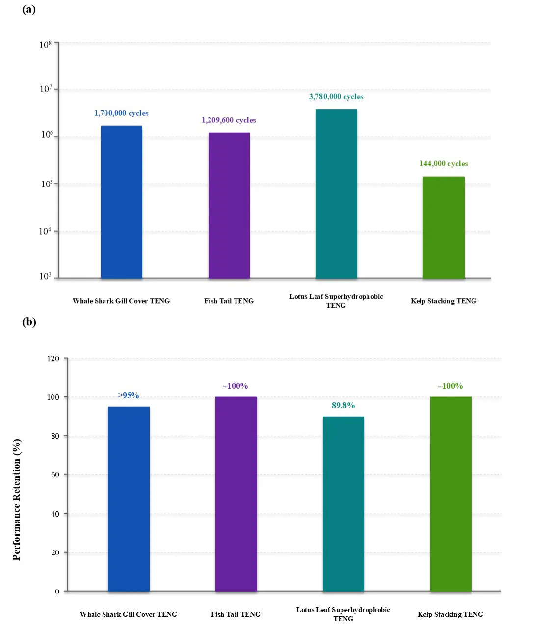
Figure 14. (a) Comparison of test duration/equivalent cycles using logarithmic coordinates; (b) Comparison of performance retention.
6. Challenges
6.1. Introduction
Chapter 3 discusses the improvements of different bionic strategies in directional adaptability, low flow response, and interface durability, while Chapter 5 compares the related performance data. Although the aforementioned bionic strategies show certain advantages in output performance, startup response, and durability, most current research still remains at the laboratory verification stage. In actual marine environments, issues such as device reliability, manufacturing scale-up, and long-term service are still insufficiently studied. Wang et al. (2025) [44] pointed out that ‘material durability remains a key challenge in marine environments’; Zhang et al. (2026) [106] noted that ‘most studies focus on idealized laboratory environments, showing a significant gap with engineering practice’; Mulvihill et al. (2025) [105] sharply pointed out that ‘TENG testing still has major defects—the testing methods, result reporting, and result interpretation all lack standardized norms’; Hao et al. (2025) [94] summarized the full chain of TENG wave energy harvesting into four stages: PTO structure, power generation unit, management circuitry, and marine applications, emphasizing that the interconnection between these stages still requires systematic optimization, as shown in Figure 15. This chapter primarily discusses the existing problems in terms of extreme sea condition reliability, design adaptability, manufacturing scale-up, and durability evaluation.
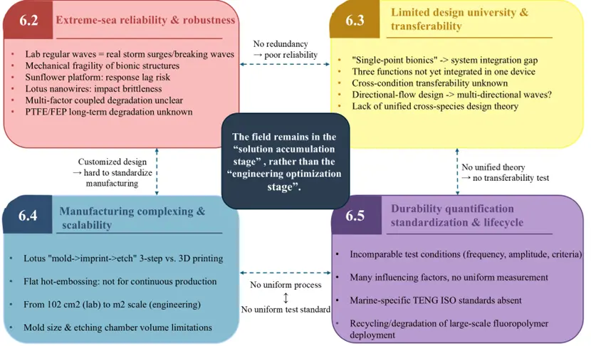
6.2. Insufficient Reliability and Robustness of Biomimetic Structures under Extreme Sea Conditions
6.2.1. Differences Between Laboratory Tests and Actual Marine Environments
All bionic strategies in Chapter 3 were validated under controlled experimental conditions—the 548% charge gain of the sunflower self-aligning platform was obtained under nearshore weak wave conditions of about 7 cm wavelength in the Beibu Gulf [48], the 18.77 W/m3 power density of kelp stacked TENG was measured in a laboratory tank with 2.5 Hz regular wave excitation [67], and the 35-day long-term test of lotus leaf superhydrophobic TENG was conducted in a laboratory tank [70], while in real marine environments, Devices also need to withstand stronger external loads such as storm surges, breaking waves, and complex flow fields. Zhang et al. (2026) [106] clearly pointed out that “most current research is still limited to ideal experimental environments, which still differ significantly from actual marine applications”. Mulvihill et al. (2025) [105] also emphasized that “TENG devices operating in real environments typically operate at frequencies below 1 Hz”, while laboratory tests are often conducted at higher frequencies. Hao et al. (2025) [94] also pointed out that “research on structural response under extreme wave loads is still very limited”.
6.2.2. Analysis of the Unique Fragility of Bionic Structures
Some complex biomimetic structures may have reliability issues in long-term marine environments. The Sunflower self-alignment platform relies on the lateral pressure difference of the droplet-shaped shell to achieve passive orientation [48], but under storm surge conditions, the passive self-alignment mechanism may experience delayed response or even irreversible deformation. Lotus leaf superhydrophobic multi-stage micro-nano structures are constructed by hot impression printing and plasma etching [70]. Whether the mechanical integrity of nanowires can be maintained long-term under continuous high-energy wave impacts remains relatively scarce. Similarly, the fatigue behavior of curved surface structures of whale shark-mimicking gill covers under extreme flow velocities has also been reported [68].
6.2.3. The Degradation Problem under the Combined Effect of Multiple Environmental Factors is Still Unclear
In the marine environment, various degradation factors such as mechanical load, chemical corrosion, biofouling, and ultraviolet aging exhibit significant coupling and strengthening effects. Zhang et al. (2026) summarized this chain of coupled degradation: “corrosion roughens the friction surface → roughening accelerates bio-adhesion → biofilm alters interfacial charge transfer characteristics” [106]. However, our current understanding of these key factors remains insufficient. In addition, the PTFE and FEP materials used in several biomimetic solutions in Chapter 3 [48,68,70] are all fluoropolymers, “whose long-term degradation behavior in the marine environment and impact on ecosystems have not been fully evaluated” [106,107,108,109,110,111,112,113,114,115,116].
6.3. Lack of a Unified Design Approach Among Different Biomimetic Strategies
1. The conflict between single-point biomimetics and system integration requirements: Chapter 3 demonstrates a prominent feature in the field of biomimetic TENGs: currently, most biomimetic solutions are primarily optimized for a specific problem—sunflowers address the directionality issue [48], kelp addresses the low-flow-start issue [67], and lotus leaves address interfacial durability issues [70]. Research that simultaneously considers directional adaptation, low-flow enhancement, and interfacial durability remains relatively scarce. Hao et al. (2025) [94] also pointed out that “the coordination between different links still requires systematic research”.
2. Insufficient adaptability across operating conditions: Biomimetic designs are usually optimized for specific conditions, but their transferability across different conditions is rarely discussed. The whale shark gill cover curved wheel is optimized for directional flow (0.22 m/s start) [68], but it is still unknown whether its curved surface guidance advantage remains effective when placed in a multidirectional random wave environment.
3. Lack of a unified design theory across biological characteristics: All the biomimetic solutions in Chapter 3 follow a “biological prototype → TENG engineering mapping” point-to-point pattern, but the field has yet to extract unified biomimetic design guidelines applicable to TENG wave energy harvesting. Hu et al. (2026) [93] also pointed out that “how to establish performance comparison benchmarks among different designs remains an open question”.
6.4. Complexity and Scalability Bottlenecks of Bionic Flexible Manufacturing
1. Challenges in large-area fabrication of micro-nano structures: The hierarchical micro-nano structures of the lotus leaf effect are the strategy with the best durability performance in Chapter 3—long-term stability over 35 days improved by about 56 times compared to flat surfaces [70]. However, the excellent surface functionality of this strategy stems from its complex fabrication process: first, photolithography and deep silicon etching are required to create thermal imprint molds; then, FEP films are embossed under high temperature and high pressure to form arrays of micron-scale pillars; finally, high-density nanowires are grown on the pillar surfaces using plasma etching [70]. This ‘mold-making—imprinting—etching’ multi-step chain presents potential yield loss at each step, and planar thermal imprinting inherently lacks the characteristics of continuous production, significantly restricting its large-area application. In contrast, other bionic strategies in Chapter 3, such as the arched gill structure of the whale shark [68], can be formed entirely in one step via 3D printing, and the stacked kelp TENG [67] requires only conventional processes such as laser cutting and silicone encapsulation. When the device area scales from the laboratory level of 102 cm2 to the engineering requirement of square meters, the size limitations of thermal imprint molds and the volume limitations of plasma etching chambers become challenging engineering problems. Therefore, although the lotus leaf effect strategy establishes an absolute advantage in interface protection performance, the clear limitations between its manufacturing process and scale-up suggest it is more suitable for key interface protection of high-value, small-area ocean sensors rather than mass production of large-area array TENGs.
2. Unclear scale effects from centimeter to meter levels: All bionic flexible schemes in Chapters 3 and 4 were validated at the centimeter scale. Scaling up is not simply geometric enlargement—the contact uniformity of friction layers deteriorates with increasing area, the internal stress distribution shifts from uniform to gradient, and the matching between dynamic response frequency and wave spectrum also changes with scale. Hu et al. (2026) [93] pointed out that the current trend of ‘advancing from single devices to arrays, and from laboratory to in-sea verification’ is evident, but systematic studies on scale effects are still lacking.
6.5. Durability Evaluation and Testing Standards Are Still Incomplete
1. Lack of unified standards for durability testing: Mulvihill et al. (2025) [105] fully revealed common issues in the field of TENG testing: “Many factors affect the electrical output of TENG—including contact force, contact area, surface roughness, elastic modulus, test frequency, separation distance, layer thickness, temperature, and humidity”. However, “many studies have not effectively controlled or measured these parameters during testing, making it difficult to directly compare them horizontally between different laboratories and testing devices” [105]. This issue is especially prominent in the bionic schemes discussed in Chapter 3—different schemes use different excitation frequencies, amplitudes, and failure criteria for durability testing, resulting in a lack of reliable basis for performance comparisons between schemes. The paper recommends “establishing a new ISO standardization committee to develop testing protocols for TENG materials and products” [105]. China released GB/T 45525.2-2025 in April 2025, marking the first step toward standardizing TENG general electrical performance testing. However, specialized testing methods and environmental adaptability evaluation systems for marine environments (wave excitation, salt spray exposure, biofouling, etc.) remain incomplete.
2. Environmental Sustainability Controversies of Fluoropolymers: Zhang et al. (2026) specifically discussed the material sustainability challenges faced by TENG, pointing out that “traditional fluoropolymers such as PTFE and FEP have excellent triboelectric properties, but their long-term degradation behavior in marine environments and their impact on ecosystems have not been fully assessed” [106]. The PTFE and FEP materials used in several biomimetic flexible solutions in Chapters 3 and 4 belong to this type of fluoropolymer, and the issues of material recycling and degradation after large-scale deployment cannot be avoided.
This chapter discusses the issues of bionic flexible TENG in extreme sea reliability, design adaptability, manufacturing scale-up, and durability evaluation. Current research has proposed various biomimetic structural schemes, but most remain at the laboratory validation stage. In actual marine applications, there is little research on issues such as long-term operation, durability, and large-scale deployment. For example, existing testing standards are not yet unified [105], the long-term degradation and impact of materials in marine environments remain unclear [106], and cross-strategy functional integration and scale-up applications also face challenges [93,94,117,118,119,120,121,122].
7. Future Development Direction
Chapter 6 has already explained that the bionic flexible TENG still faces issues such as reliability, manufacturing scale-up, and long-term stability in real marine environments. Although various bionic flexible strategies in Chapters 3 and 4 have shown certain advantages in directional adaptation, low flow response, and interfacial durability, most results still mainly come from laboratory conditions. Compared to instantaneous output parameters, the device’s long-term operational capability in complex sea conditions may currently be even more critical. In addition, there is still a lack of unified design methods among different bionic flexible strategies. Most existing studies focus on optimizing for a single problem, with relatively limited multifunctional collaboration capabilities. Meanwhile, issues such as material environmental impact, scale scale-up, and inconsistent testing standards will further limit subsequent engineering applications [93], as shown in Figure 16. Based on the above issues, this chapter mainly discusses the possible future development directions of bionic flexible TENG from three aspects: material optimization, multifunctional structural design, and engineering applications.
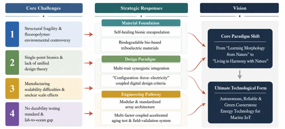
7.1. Directions for Material Optimization in Complex Marine Environments
1. Environmentally Adaptive and Self-Healing Materials: As mentioned in Chapter 6, some superhydrophobic micro-nano structures may suffer from insufficient mechanical stability under strong impacts or long-term wave action. Compared with relying solely on surface structures for ‘passive protection’, future research may focus more on encapsulation materials with environmental responsiveness. For example, self-healing elastomers have already shown certain potential in the field of flexible electronics. Xu et al. (2025) [123] pointed out that materials based on multiple hydrogen bonds and reversible covalent bonds can still maintain a certain repair ability under low-temperature conditions. If applied to the outer encapsulation of TENGs, the material could restore structural integrity to some extent after cracks or local damage occur on the device surface, thereby reducing the impact of seawater infiltration on the internal friction interfaces. However, current research is still primarily conducted under laboratory conditions. The stability of these materials under long-term combined effects of salt spray, high humidity, and cyclic mechanical loads still needs further verification.
2. Biodegradable Triboelectric Materials: In response to the environmental persistence issues of fluorinated polymers mentioned in Chapter 6, biodegradable triboelectric materials are also one of the future areas of focus. Shi et al. (2025) [124] have constructed biodegradable TENGs using collagen fibers and MXene composites. Although their current output performance still lags behind traditional materials such as PTFE and FEP, they have already shown certain application potential in single-use marine sensors or low-power auxiliary units. Future research may need to further balance output performance, material lifespan, and environmental impact. Compared with merely pursuing higher output, the long-term sustainability of materials in marine environments may gradually become a more important issue in the future.
7.2. Trends in the Co-Design of Multifunctional Bionic Structures
1. Collaborative integration of multiple bionic features: Most bionic strategies in Chapter 3 are mainly optimized for a specific type of problem. For example, the sunflower structure emphasizes directional adaptability, the kelp structure emphasizes low-flow response, and the lotus leaf structure is primarily used to improve interfacial stability. But problems in real marine environments are often not isolated in a single area. During actual operation, devices may face multiple effects such as random waves, biological fouling, and long-term mechanical fatigue. Therefore, relying solely on a single bionic feature may be difficult to meet long-term engineering application needs. Against this backdrop, future research may focus more on collaborative design among multifunctional structures. For example, by simultaneously combining direction-adaptive structures, flexible fluid-structure coupling structures, and surface anti-fouling interfaces within the same device, the device’s comprehensive adaptability in complex environments can be improved. However, multifunctional integration may also lead to increased structural complexity, greater processing difficulty, and more complex internal coupling relationships, which still require further research.
2. Data-based and model-based design methods: Currently, most bionic flexible TENG designs still rely mainly on empirical structural imitation, lacking unified design foundations across different studies. With the development of CFD simulation and fluid-structure coupling analysis, subsequent research may gradually shift from “shape imitation” to “parametric design”. For example, the whale shark-mimicking gill cover TENG has used CFD analysis to explain the influence of curved curves on local flow fields [68]. In the future, if a correlation model between “structural parameters—flow field response—electrical output” can be further established, performance comparisons and optimization processes among different bionic structures may become more systematic. In addition, AI-assisted optimization methods may gradually be used for parameter screening of bionic structures. However, related research is still relatively limited, and its applicability in complex marine environments still requires further verification.
7.3. Directions for Engineering Development Oriented Toward Practical Marine Applications
1. Modular and Array Deployment: Chapter 6 points out that most bionic TENGs are still at the centimeter-level laboratory prototype stage, and significant scale effects remain in the process from single devices to large-scale array scale-up. Therefore, modular design may become one of the more practical directions for future development. By designing individual TENG units as standardized modules, the difficulty of subsequent array deployment and maintenance can be reduced. The 3D printed planetary gear frequency multiplier TENG network proposed by Li et al. (2025) [125] already reflects a modular array design approach to some extent. In the future, if packaging interfaces, power management modules, and sensor units can be further unified, device deployment efficiency in actual marine environments may improve. However, after arraying, issues such as flow field interference, electrical coupling, and long-term synchronization stability between different units still lack long-term real sea data support.
2. Multi-factor coupling testing and long-term real-sea validation: Currently, many teng durability results are still mainly derived from single-factor experimental conditions, while degradation in real marine environments often exhibits obvious coupling characteristics. Therefore, subsequent research may need to establish a testing system that is closer to real sea conditions. For example, considering factors such as mechanical impact, salt spray corrosion, UV aging, and biological contamination, a comprehensive long-term stability assessment of the device is conducted. At the same time, long-term real-sea validation may become increasingly important. Compared to short-cycle laboratory tests, long-term operational data from real sea areas better reflects the device’s actual service capability. However, there are still a few publicly available long-term ocean validation cases, and related standardized testing systems are still incomplete.
7.4. Conclusions
Overall, the future development focus of bionic flexible TENGs may gradually shift from improving single performance metrics to comprehensive adaptability in complex marine environments. In addition to output performance, long-term stability, material durability, environmental impact, and system integration capability may all become increasingly critical issues. Currently, directions such as self-healing materials, multifunctional synergistic structures, and modular array deployment have shown some potential, but a significant gap remains before large-scale practical marine applications can be achieved. Moreover, there remain obvious differences between laboratory conditions and real marine environments. Future research may need to further strengthen long-term field validations and the establishment of standardized testing systems to improve the comparability of research results and their engineering reference value.
Statement of the Use of Generative AI and AI-Assisted Technologies in the Writing Process
During the preparation of this manuscript, the authors used Deepseek in order to polishing language, checking grammar, and summarizing literature. After using this tool, the authors reviewed and edited the content as needed and takes full responsibility for the content of the published article.
Author Contributions
Conceptualization, D.Z. and Y.L.; methodology, D.Z. and Z.L.; software, K.Y.; validation, D.Z., S.Z. and Y.L.; formal analysis, D.Z.; investigation, D.Z.; resources, D.Z. and K.Y.; data curation, D.Z.; writing—original draft preparation, D.Z. and Y.L.; writing—review and editing, D.Z., Y.L. and K.Y.; visualization, K.Y.; supervision, D.Z.; project administration, D.Z.; funding acquisition, D.Z. All authors have read and agreed to the published version of the manuscript.
Ethics Statement
Not applicable.
Informed Consent Statement
Not applicable.
Data Availability Statement
No new data were created or analyzed in this study. Data sharing is not applicable to this article.
Funding
This research received no external funding.
Declaration of Competing Interest
The authors declare that they have no known competing financial interests or personal relationships that could have appeared to influence the work reported in this paper.
References
- Falnes J. A review of wave-energy extraction. Mar. Struct. 2007, 20, 185–201. DOI:10.1016/j.marstruc.2007.09.001 [Google Scholar]
- Falcão AFDO. Wave energy utilization: A review of the technologies. Renew. Sustain. Energy Rev. 2010, 14, 899–918. DOI:10.1016/j.rser.2009.11.003 [Google Scholar]
- Drew B, Plummer AR, Sahinkaya MN. A review of wave energy converter technology. Proc. Inst. Mech. Eng. A J. Power Energy 2009, 223, 887–902. DOI:10.1243/09576509JPE782 [Google Scholar]
- López I, Andreu J, Ceballos S, Martínez de Alegría I, Kortabarria I. Review of wave energy technologies and the necessary power-equipment. Renew. Sustain. Energy Rev. 2013, 27, 413–434. DOI:10.1016/j.rser.2013.07.009 [Google Scholar]
- Astariz S, Iglesias G. The economics of wave energy: A review. Renew. Sustain. Energy Rev. 2015, 45, 397–408. DOI:10.1016/j.rser.2015.01.061 [Google Scholar]
- Gunn K, Stock-Williams C. Quantifying the global wave power resource. Renew. Energy 2012, 44, 296–304. DOI:10.1016/j.renene.2012.01.101 [Google Scholar]
- Mørk G, Barstow S, Kabuth A, Pontes MT. Assessing the Global Wave Energy Potential. In Proceedings of the 29th International Conference on Ocean, Offshore and Arctic Engineering, Shanghai, China, 6–11 June 2010; pp. 447–454. DOI:10.1115/OMAE2010-20473 [Google Scholar]
- Reguero BG, Losada IJ, Méndez FJ. A global wave power resource and its seasonal, interannual and long-term variability. Appl. Energy 2015, 148, 366–380. DOI:10.1016/j.apenergy.2015.03.114 [Google Scholar]
- Reguero BG, Losada IJ, Méndez FJ. A recent increase in global wave power as a consequence of oceanic warming. Nat. Commun. 2019, 10, 205. DOI:10.1038/s41467-018-08066-0 [Google Scholar]
- Rusu E, Onea F. A review of the technologies for wave energy extraction. Clean Energy 2018, 2, 10–19. DOI:10.1093/ce/zky003 [Google Scholar]
- Penalba M, Ringwood J. A Review of Wave-to-Wire Models for Wave Energy Converters. Energies 2016, 9, 506. DOI:10.3390/en9070506 [Google Scholar]
- Guo B, Ringwood JV. A review of wave energy technology from a research and commercial perspective. ET Renew. Power Gener. 2021, 15, 3065–3090. DOI:10.1049/rpg2.12302 [Google Scholar]
- Wang ZL. Triboelectric Nanogenerators as New Energy Technology for Self-Powered Systems and as Active Mechanical and Chemical Sensors. ACS Nano 2013, 7, 9533–9557. DOI:10.1021/nn404614z [Google Scholar]
- Wu C, Wang AC, Ding W, Guo H, Wang ZL. Triboelectric Nanogenerator: A Foundation of the Energy for the New Era. Adv. Energy Mater. 2019, 9, 1802906. DOI:10.1002/aenm.201802906 [Google Scholar]
- Niu S, Wang S, Lin L, Liu Y, Zhou YS, Hu Y, et al. Theoretical study of contact-mode triboelectric nanogenerators as an effective power source. Energy Environ. Sci. 2013, 6, 3576. DOI:10.1039/c3ee42571a [Google Scholar]
- Wang ZL, Wang AC. On the origin of contact-electrification. Mater. Today 2019, 30, 34–51. DOI:10.1016/j.mattod.2019.05.016 [Google Scholar]
- Wang ZL, Lin L, Chen J, Niu S, Zi Y. Triboelectric Nanogenerators; Springer: Cham, Switzerland, 2016. DOI:10.1007/978-3-319-40039-6 [Google Scholar]
- Zhong YH, Yan J, Mei N, Wei B. Research Progress on Wave Energy Generation Technology Based on Triboelectric Nanogenerators. J. Ocean. Technol. 2022, 41, 97–107. DOI:10.3969/j.issn.1003-2029.2022.03.012 [Google Scholar]
- Fan FR, Tian ZQ, Wang ZL. Flexible triboelectric generator. Nano Energy 2012, 1, 328–334. DOI:10.1016/j.nanoen.2012.01.004 [Google Scholar]
- Zhu G, Pan C, Guo W, Chen CY, Zhou Y, Yu R, et al. Triboelectric-Generator-Driven Pulse Electrodeposition for Micropatterning. Nano Lett. 2012, 12, 4960–4965. DOI:10.1021/nl302560k [Google Scholar]
- Xu C, Zi Y, Wang AC, Zou H, Dai Y, He X, et al. On the Electron‐Transfer Mechanism in the Contact‐Electrification Effect. Adv. Mater. 2018, 30, 1706790. DOI:10.1002/adma.201706790 [Google Scholar]
- Wang ZL. On Maxwell’s displacement current for energy and sensors: The origin of nanogenerators. Mater. Today 2017, 20, 74–82. DOI:10.1016/j.mattod.2016.12.001 [Google Scholar]
- Lin S, Xu L, Xu C, Chen X, Wang AC, Zhang B, et al. Electron Transfer in Nanoscale Contact Electrification: Effect of Temperature in the Metal–Dielectric Case. Adv. Mater. 2019, 31, 1808197. DOI:10.1002/adma.201808197 [Google Scholar]
- Xu C, Zhang B, Wang AC, Zou H, Liu G, Ding W, et al. Contact-Electrification between Two Identical Materials: Curvature Effect. ACS Nano 2019, 13, 2034–2041. DOI:10.1021/acsnano.8b08533 [Google Scholar]
- Wang ZL. Triboelectric nanogenerators as new energy technology and self-powered sensors—Principles, problems and perspectives. Faraday Discuss. 2014, 176, 447–458. DOI:10.1039/C4FD00159A [Google Scholar]
- Yao YJ, Zhang P, Wang DX, Li YX, Huang LS. Research Progress on Wave Energy Harvesting Systems Based on Triboelectric Nanogenerators. Micronano. Electron. Technol. 2022, 59, 107–117+144. DOI:10.13250/j.cnki.wndz.2022.02.001 [Google Scholar]
- Niu S, Liu Y, Wang S, Lin L, Zhou YS, Hu Y, et al. Theory of Sliding‐Mode Triboelectric Nanogenerators. Adv. Mater. 2013, 25, 6184–6193. DOI:10.1002/adma.201302808 [Google Scholar]
- Yang Y, Zhang H, Chen J, Jing Q, Zhou YS, Wen X, et al. Single-Electrode-Based Sliding Triboelectric Nanogenerator for Self-Powered Displacement Vector Sensor System. ACS Nano 2013, 7, 7342–7351. DOI:10.1021/nn403021m [Google Scholar]
- Zhang H, Yang Y, Su Y, Chen J, Adams K, Lee S, et al. Triboelectric Nanogenerator for Harvesting Vibration Energy in Full Space and as Self‐Powered Acceleration Sensor. Adv. Funct. Mater. 2014, 24, 1401–1407. DOI:10.1002/adfm.201302453 [Google Scholar]
- Zhao Z, Wang J. Advances in Interfacial Electrostatic Energy Harvesting via Direct Current Triboelectric Nanogenerators. Adv. Energy Mater. 2025, 15, 2502544. DOI:10.1002/aenm.202502544 [Google Scholar]
- Chung SH, Lee S, Chung J. Electrostatic discharge as a breakthrough strategy for triboelectric nanogenerators. Commun. Mater. 2026, 7, 191. DOI:10.1038/s43246-026-01289-5 [Google Scholar]
- Salman M, Sorokin V, Aw K. Systematic literature review of wave energy harvesting using triboelectric nanogenerator. Renew. Sustain. Energy Rev. 2024, 201, 114626. DOI:10.1016/j.rser.2024.114626 [Google Scholar]
- Wang X, Niu S, Yin Y, Yi F, You Z, Wang ZL. Triboelectric Nanogenerator Based on Fully Enclosed Rolling Spherical Structure for Harvesting Low‐Frequency Water Wave Energy. Adv. Energy Mater. 2015, 5, 1501467. DOI:10.1002/aenm.201501467 [Google Scholar]
- Zhu G, Su Y, Bai P, Chen J, Jing Q, Yang W, et al. Harvesting Water Wave Energy by Asymmetric Screening of Electrostatic Charges on a Nanostructured Hydrophobic Thin-Film Surface. ACS Nano 2014, 8, 6031–6037. DOI:10.1021/nn5012732 [Google Scholar]
- Chen J, Yang J, Li Z, Fan X, Zi Y, Jing Q, et al. Networks of Triboelectric Nanogenerators for Harvesting Water Wave Energy: A Potential Approach toward Blue Energy. ACS Nano 2015, 9, 3324–3331. DOI:10.1021/acsnano.5b00534 [Google Scholar]
- Wang X, Wen Z, Guo H, Wu C, He X, Lin L, et al. Fully Packaged Blue Energy Harvester by Hybridizing a Rolling Triboelectric Nanogenerator and an Electromagnetic Generator. ACS Nano 2016, 10, 11369–11376. DOI:10.1021/acsnano.6b06622 [Google Scholar]
- Xu L, Pang Y, Zhang C, Jiang T, Chen X, Luo J, et al. Integrated triboelectric nanogenerator array based on air-driven membrane structures for water wave energy harvesting. Nano Energy 2017, 31, 351–358. DOI:10.1016/j.nanoen.2016.11.037 [Google Scholar]
- Wang ZL. Catch wave power in floating nets. Nature 2017, 542, 159–160. DOI:10.1038/542159a [Google Scholar]
- Li X, Tao J, Wang X, Zhu J, Pan C, Wang ZL. Networks of High Performance Triboelectric Nanogenerators Based on Liquid–Solid Interface Contact Electrification for Harvesting Low‐Frequency Blue Energy. Adv. Energy Mater. 2018, 8, 1800705. DOI:10.1002/aenm.201800705 [Google Scholar]
- Xu L, Jiang T, Lin P, Shao JJ, He C, Zhong W, et al. Coupled Triboelectric Nanogenerator Networks for Efficient Water Wave Energy Harvesting. ACS Nano 2018, 12, 1849–1858. DOI:10.1021/acsnano.7b08674 [Google Scholar]
- Rodrigues C, Nunes D, Clemente D, Mathias N, Correia JM, Rosa-Santos P, et al. Emerging triboelectric nanogenerators for ocean wave energy harvesting: State of the art and future perspectives. Energy Environ. Sci. 2020, 13, 2657–2683. DOI:10.1039/D0EE01258K [Google Scholar]
- Wang ZL. Entropy theory of distributed energy for internet of things. Nano Energy 2019, 58, 669–672. DOI:10.1016/j.nanoen.2019.02.012 [Google Scholar]
- Lou Y, Li M, Yu A, Zhai J, Wang ZL. From Wave Energy to Electricity: Functional Design and Performance Analysis of Triboelectric Nanogenerators. Nano-Micro Lett. 2025, 17, 298. DOI:10.1007/s40820-025-01811-3 [Google Scholar]
- Wang ZL, Jiang T, Ma T, Yang R. Nanogenerators for blue energy. MRS Bull. 2025, 50, 450–458. DOI:10.1557/s43577-025-00876-0 [Google Scholar]
- Qiu H, Wang H, Xu L, Zheng M, Wang ZL. Brownian motor inspired monodirectional continuous spinning triboelectric nanogenerators for extracting energy from irregular gentle water waves. Energy Environ. Sci. 2023, 16, 473–483. DOI:10.1039/D2EE03395J [Google Scholar]
- Jiang T, Chen X, Yang K, Han C, Tang W, Wang ZL. Theoretical study on rotary-sliding disk triboelectric nanogenerators in contact and non-contact modes. Nano Res. 2016, 9, 1057–1070. DOI:10.1007/s12274-016-0997-x [Google Scholar]
- Wen Z, Guo H, Zi Y, Yeh MH, Wang X, Deng J, et al. Harvesting Broad Frequency Band Blue Energy by a Triboelectric–Electromagnetic Hybrid Nanogenerator. ACS Nano 2016, 10, 6526–6534. DOI:10.1021/acsnano.6b03293 [Google Scholar]
- Li H, Tang W, Li J, Zhou W, Wen H, Xie C, et al. Butterfly-stacked triboelectric nanogenerator with self-adaptive platform for all-angle weak wave energy harvesting. Nano Energy 2025, 144, 111347. DOI:10.1016/j.nanoen.2025.111347 [Google Scholar]
- Zhang S, Shi Z, Yuan X, Qiu Y, Xue C, Zhu Y, et al. Fish schooling effect triboelectric nanogenerators array. Nano Energy 2025, 142, 111263. DOI:10.1016/j.nanoen.2025.111263 [Google Scholar]
- Yang B, Li H, Wang Z, Wang J, Dong L, Yu Y, et al. High-performance triboelectric nanogenerator inspired by bionic jellyfish for wave energy harvesting. Chem. Eng. J. 2025, 503, 158399. DOI:10.1016/j.cej.2024.158399 [Google Scholar]
- Gulahmadov O, Muradov M, Gahramanli L, Kim J. Origami-inspired wave-driven triboelectric nanogenerator based on polysiloxane and nylon films for self-powered marine monitoring. Next Res. 2026, 8, 101574. DOI:10.1016/j.nexres.2026.101574 [Google Scholar]
- Zhou H, Wang X, Nan Y, Zhai X, Yang L, Sun Y, et al. Hybrid Nanogenerator Inspired by Biomimetic Structure of Bird Fluttering Wings. ACS Appl. Mater. Interfaces 2025, 17, 28894–28907. DOI:10.1021/acsami.5c04113 [Google Scholar]
- Zi Y, Guo H, Wen Z, Yeh MH, Hu C, Wang ZL. Harvesting Low-Frequency (<5 Hz) Irregular Mechanical Energy: A Possible Killer Application of Triboelectric Nanogenerator. ACS Nano 2016, 10, 4797–4805. DOI:10.1021/acsnano.6b01569 [Google Scholar]
- Zhao X, Askari H, Chen J. Nanogenerators for smart cities in the era of 5G and Internet of Things. Joule 2021, 5, 1391–1431. DOI:10.1016/j.joule.2021.03.013 [Google Scholar]
- Liu D, Yin X, Guo H, Zhou L, Li X, Zhang C, et al. A constant current triboelectric nanogenerator arising from electrostatic breakdown. Sci. Adv. 2019, 5, eaav6437. DOI:10.1126/sciadv.aav6437 [Google Scholar]
- Lin S, Chen X, Wang ZL. Contact Electrification at the Liquid–Solid Interface. Chem. Rev. 2022, 122, 5209–5232. DOI:10.1021/acs.chemrev.1c00176 [Google Scholar]
- Nie J, Ren Z, Shao J, Deng C, Xu L, Chen X, et al. Self-Powered Microfluidic Transport System Based on Triboelectric Nanogenerator and Electrowetting Technique. ACS Nano 2018, 12, 1491–1499. DOI:10.1021/acsnano.7b08014 [Google Scholar]
- Lin Z, Cheng G, Lee S, Pradel KC, Wang ZL. Harvesting Water Drop Energy by a Sequential Contact‐Electrification and Electrostatic‐Induction Process. Adv. Mater. 2014, 26, 4690–4696. DOI:10.1002/adma.201400373 [Google Scholar]
- Wang S, Xie Y, Niu S, Lin L, Wang ZL. Freestanding Triboelectric‐Layer‐Based Nanogenerators for Harvesting Energy from a Moving Object or Human Motion in Contact and Non‐contact Modes. Adv. Mater. 2014, 26, 2818–2824. DOI:10.1002/adma.201305303 [Google Scholar]
- Xu W, Zheng H, Liu Y, Zhou X, Zhang C, Song Y, et al. A droplet-based electricity generator with high instantaneous power density. Nature 2020, 578, 392–396. DOI:10.1038/s41586-020-1985-6 [Google Scholar]
- Lin ZH, Cheng G, Wu W, Pradel KC, Wang ZL. Dual-Mode Triboelectric Nanogenerator for Harvesting Water Energy and as a Self-Powered Ethanol Nanosensor. ACS Nano 2014, 8, 6440–6448. DOI:10.1021/nn501983s [Google Scholar]
- Tian J, Shi R, Liu Z, Ouyang H, Yu M, Zhao C, et al. Self-powered implantable electrical stimulator for osteoblasts’ proliferation and differentiation. Nano Energy 2019, 59, 705–714. DOI:10.1016/j.nanoen.2019.02.073 [Google Scholar]
- Chen J, Guo H, He X, Liu G, Xi Y, Shi H, et al. Enhancing Performance of Triboelectric Nanogenerator by Filling High Dielectric Nanoparticles into Sponge PDMS Film. ACS Appl. Mater. Interfaces 2016, 8, 736–744. DOI:10.1021/acsami.5b09907 [Google Scholar]
- Wang S, Lin L, Wang ZL. Nanoscale Triboelectric-Effect-Enabled Energy Conversion for Sustainably Powering Portable Electronics. Nano Lett. 2012, 12, 6339–6346. DOI:10.1021/nl303573d [Google Scholar]
- Fan FR, Lin L, Zhu G, Wu W, Zhang R, Wang ZL. Transparent Triboelectric Nanogenerators and Self-Powered Pressure Sensors Based on Micropatterned Plastic Films. Nano Lett. 2012, 12, 3109–3114. DOI:10.1021/nl300988z [Google Scholar]
- Zhu G, Lin ZH, Jing Q, Bai P, Pan C, Yang Y, et al. Toward Large-Scale Energy Harvesting by a Nanoparticle-Enhanced Triboelectric Nanogenerator. Nano Lett. 2013, 13, 847–853. DOI:10.1021/nl4001053 [Google Scholar]
- Sun C, Liu X, Zhong W, Pan Q, Chen L, Zhang G, et al. A Kelp Inspired High‐Power Density Triboelectric Nanogenerator with Stacking Structure for Multiple Directional Ocean Wave Energy Harvesting. Adv. Mater. Technol. 2025, 10, 2401183. DOI:10.1002/admt.202401183 [Google Scholar]
- Zhang J, Li H, Wang J, He S, Wang X, Yu Y, et al. A Flexible Rolling Triboelectric Nanogenerator with a Bionic Gill Cover Structure for Low‐Velocity Water Flow Energy Harvesting. Small 2025, 21, 2409864. DOI:10.1002/smll.202409864 [Google Scholar]
- Zhang Y, Cao X, Wang ZL. The sealed bionic fishtail-structured TENG based on anticorrosive paint for ocean sensor systems. Nano Energy 2023, 108, 108210. DOI:10.1016/j.nanoen.2023.108210 [Google Scholar]
- Zhao XJ, Zhu G, Zhao ZH, Wang ZL, Wang J. High durable bio-inspired self-cleaning solid-liquid contact triboelectric nanogenerator for water wave energy harvesting. Nano Energy 2025, 139, 110971. DOI:10.1016/j.nanoen.2025.110971 [Google Scholar]
- Yeh C, Kao FC, Wei PH, Pal A, Kaswan K, Huang YT, et al. Bioinspired shark skin-based liquid metal triboelectric nanogenerator for self-powered gait analysis and long-term rehabilitation monitoring. Nano Energy 2022, 104, 107852. DOI:10.1016/j.nanoen.2022.107852 [Google Scholar]
- Wang Y, Liu X, Chen T, Wang H, Zhu C, Yu H, et al. An underwater flag-like triboelectric nanogenerator for harvesting ocean current energy under extremely low velocity condition. Nano Energy 2021, 90, 106503. DOI:10.1016/j.nanoen.2021.106503 [Google Scholar]
- Huang X, Xing C, Zhou Z, Zuo-Jiang S, Sun D, Chen G, et al. Underwater high-performance flag-shaped triboelectric nanogenerator for harvesting energy in ultraslow water current. Nano Energy 2025, 135, 110664. DOI:10.1016/j.nanoen.2025.110664 [Google Scholar]
- Wang Y, Liu X, Wang Y, Wang H, Wang H, Zhang SL, et al. Flexible Seaweed-Like Triboelectric Nanogenerator as a Wave Energy Harvester Powering Marine Internet of Things. ACS Nano 2021, 15, 15700–15709. DOI:10.1021/acsnano.1c05127 [Google Scholar]
- Wang H. Research on Wave Energy Harvesting Technology Based on Flexible Seagrass-Type Triboelectric Nanogenerators. Master’s Thesis, Dalian Maritime University, Dalian, China, 2020. DOI:10.26989/d.cnki.gdlhu.2020.001206 [Google Scholar]
- Deng Z, Xu L, Qin H, Li X, Duan J, Hou B, et al. Rationally Structured Triboelectric Nanogenerator Arrays for Harvesting Water‐Current Energy and Self‐Powered Sensing. Adv. Mater. 2022, 34, 2205064. DOI:10.1002/adma.202205064 [Google Scholar]
- Qian Y. Extended Research on the Water Environmental Applications of Flexible Triboelectric Nanogenerators. Master’s Thesis, Nanjing University of Aeronautics and Astronautics, Nanjing, China, 2020. DOI:10.27239/d.cnki.gnhhu.2020.000965 [Google Scholar]
- Jing HT. Research on a Triboelectric-Electromagnetic Hybrid Wave Energy Harvester Driven by Non-Inertial Forces. Master’s Thesis, Guangxi University, Nanning, China, 2024. DOI:10.27034/d.cnki.ggxiu.2024.003185 [Google Scholar]
- Mannsfeld SCB, Tee BCK, Stoltenberg RM, Chen CVHH, Barman S, Muir BVO, et al. Highly sensitive flexible pressure sensors with microstructured rubber dielectric layers. Nature Mater. 2010, 9, 859–864. DOI:10.1038/nmat2834 [Google Scholar]
- Kim DH, Lu N, Ma R, Kim YS, Kim RH, Wang S, et al. Epidermal Electronics. Science 2011, 333, 838–843. DOI:10.1126/science.1206157 [Google Scholar]
- Rogers JA, Someya T, Huang Y. Materials and Mechanics for Stretchable Electronics. Science 2010, 327, 1603–1607. DOI:10.1126/science.1182383 [Google Scholar]
- Wang S, Lin L, Wang ZL. Triboelectric nanogenerators as self-powered active sensors. Nano Energy 2015, 11, 436–462. DOI:10.1016/j.nanoen.2014.10.034 [Google Scholar]
- Park K, Lee M, Liu Y, Moon S, Hwang G, Zhu G, et al. Flexible Nanocomposite Generator Made of BaTiO3 Nanoparticles and Graphitic Carbons. Adv. Mater. 2012, 24, 2999–3004. DOI:10.1002/adma.201200105 [Google Scholar]
- Pi Z, Zhang J, Wen C, Zhang ZB, Wu D. Flexible piezoelectric nanogenerator made of poly(vinylidenefluoride-co-trifluoroethylene) (PVDF-TrFE) thin film. Nano Energy 2014, 7, 33–41. DOI:10.1016/j.nanoen.2014.04.016 [Google Scholar]
- Yuk H, Lu B, Zhao X. Hydrogel bioelectronics. Chem. Soc. Rev. 2019, 48, 1642–1667. DOI:10.1039/C8CS00595H [Google Scholar]
- Li J, Celiz AD, Yang J, Yang Q, Wamala I, Whyte W, et al. Tough adhesives for diverse wet surfaces. Science 2017, 357, 378–381. DOI:10.1126/science.aah6362 [Google Scholar]
- Baik S, Kim DW, Park Y, Lee TJ, Ho Bhang S, Pang C. A wet-tolerant adhesive patch inspired by protuberances in suction cups of octopi. Nature 2017, 546, 396–400. DOI:10.1038/nature22382 [Google Scholar]
- Tee BCK, Wang C, Allen R, Bao Z. An electrically and mechanically self-healing composite with pressure- and flexion-sensitive properties for electronic skin applications. Nat. Nanotechnol. 2012, 7, 825–832. DOI:10.1038/nnano.2012.192 [Google Scholar]
- Kang J, Tok JBH, Bao Z. Self-healing soft electronics. Nat. Electron. 2019, 2, 144–150. DOI:10.1038/s41928-019-0235-0 [Google Scholar]
- Zheng Q, Shi B, Fan F, Wang X, Yan L, Yuan W, et al. In Vivo Powering of Pacemaker by Breathing‐Driven Implanted Triboelectric Nanogenerator. Adv. Mater. 2014, 26, 5851–5856. DOI:10.1002/adma.201402064 [Google Scholar]
- Zheng Q, Zou Y, Zhang Y, Liu Z, Shi B, Wang X, et al. Biodegradable triboelectric nanogenerator as a life-time designed implantable power source. Sci. Adv. 2016, 2, e1501478. DOI:10.1126/sciadv.1501478 [Google Scholar]
- Jiang W, Li H, Liu Z, Li Z, Tian J, Shi B, et al. Fully Bioabsorbable Natural‐Materials‐Based Triboelectric Nanogenerators. Adv. Mater. 2018, 30, 1801895. DOI:10.1002/adma.201801895 [Google Scholar]
- Hu C, Wang Y, Qi L, Song J, Chen J, Kang H, et al. Triboelectric nanogenerators for wave energy harvesting and self-powered smart sensing applications. Nano Energy 2026, 148, 111657. DOI:10.1016/j.nanoen.2025.111657 [Google Scholar]
- Hao Y, Wu C, Zang K, Zhang L, Zhou J, Zhao D. Research advances of triboelectric nanogenerators for blue energy: Research status, challenges and future outlook. Nano Energy 2025, 142, 111223. DOI:10.1016/j.nanoen.2025.111223 [Google Scholar]
- Xi Z, Du H, Wang Y, Yu H, Dai S, Fan M, et al. A ternary-dielectric rolling TENG array for robust ocean energy harvesting and distributed environmental monitoring. Nano Energy 2025, 143, 111318. DOI:10.1016/j.nanoen.2025.111318 [Google Scholar]
- Xi F, Pang Y, Li W, Jiang T, Zhang L, Guo T, et al. Universal power management strategy for triboelectric nanogenerator. Nano Energy 2017, 37, 168–176. DOI:10.1016/j.nanoen.2017.05.027 [Google Scholar]
- Niu S, Wang X, Yi F, Zhou YS, Wang ZL. A universal self-charging system driven by random biomechanical energy for sustainable operation of mobile electronics. Nat. Commun. 2015, 6, 8975. DOI:10.1038/ncomms9975 [Google Scholar]
- Cheng L, Xu Q, Zheng Y, Jia X, Qin Y. A self-improving triboelectric nanogenerator with improved charge density and increased charge accumulation speed. Nat Commun 2018, 9, 3773. DOI:10.1038/s41467-018-06045-z [Google Scholar]
- Tang W, Han Y, Han CB, Gao CZ, Cao X, Wang ZL. Self-powered water splitting using flowing kinetic energy. Adv. Mater. 2015, 27, 272–276. DOI:10.1002/adma.201404071 [Google Scholar]
- Xu S, Zhang Y, Cho J, Lee J, Huang X, Jia L, et al. Stretchable batteries with self-similar serpentine interconnects and integrated wireless recharging systems. Nat. Commun. 2013, 4, 1543. DOI:10.1038/ncomms2553 [Google Scholar]
- Wang ZL. Self‐Powered Nanosensors and Nanosystems. Adv. Mater. 2012, 24, 280–285. DOI:10.1002/adma.201102958 [Google Scholar]
- Askari H, Khajepour A, Khamesee MB, Saadatnia Z, Wang ZL. Piezoelectric and triboelectric nanogenerators: Trends and impacts. Nano Today 2018, 22, 10–13. DOI:10.1016/j.nantod.2018.08.001 [Google Scholar]
- Akyildiz IF, Pompili D, Melodia T. Underwater acoustic sensor networks: Research challenges. Ad. Hoc. Netw. 2005, 3, 257–279. DOI:10.1016/j.adhoc.2005.01.004 [Google Scholar]
- Xu G, Shi Y, Sun X, Shen W. Internet of Things in Marine Environment Monitoring: A Review. Sensors 2019, 19, 1711. DOI:10.3390/s19071711 [Google Scholar]
- Mulvihill DM, Mukherjee R, Xu Y, Kumar C, Khandelwal G, Perris J, et al. How to Test Triboelectric Nanogenerators: Key Factors for Standardized Performance Evaluation. Adv. Energy Mater. 2025, 15, e02920. DOI:10.1002/aenm.202502920 [Google Scholar]
- Zhang D, Wu Y, Zhang Y, Zhang H, Zhou L, Yang C, et al. Triboelectric nanogenerators for self-powered metal anti-corrosion and marine anti-fouling. Nano Energy 2026, 147, 111605. DOI:10.1016/j.nanoen.2025.111605 [Google Scholar]
- Callow JA, Callow ME. Trends in the development of environmentally friendly fouling-resistant marine coatings. Nat. Commun. 2011, 2, 244. DOI:10.1038/ncomms1251 [Google Scholar]
- Lejars M, Margaillan A, Bressy C. Fouling Release Coatings: A Nontoxic Alternative to Biocidal Antifouling Coatings. Chem. Rev. 2012, 112, 4347–4390. DOI:10.1021/cr200350v [Google Scholar]
- Dafforn KA, Lewis JA, Johnston EL. Antifouling strategies: History and regulation, ecological impacts and mitigation. Mar. Pollut. Bull. 2011, 62, 453–465. DOI:10.1016/j.marpolbul.2011.01.012 [Google Scholar]
- Roberge PR. Handbook of Corrosion Engineering; McGraw-Hill: New York, NY, USA, 2000. [Google Scholar]
- Revie RW, Uhlig HH. Corrosion and Corrosion Control; Wiley-Interscience: Hoboken, NJ, USA, 2008. DOI:10.1002/9780470277270 [Google Scholar]
- Melchers RE. A Review of Trends for Corrosion Loss and Pit Depth in Longer-Term Exposures. Corros. Mater. Degrad. 2018, 1, 42–58. DOI:10.3390/cmd1010004 [Google Scholar]
- Andrady AL. Microplastics in the marine environment. Mar. Pollut. Bull. 2011, 62, 1596–1605. DOI:10.1016/j.marpolbul.2011.05.030 [Google Scholar]
- Geyer R, Jambeck JR, Law KL. Production, use, and fate of all plastics ever made. Sci. Adv. 2017, 3, e1700782. DOI:10.1126/sciadv.1700782 [Google Scholar]
- Cousins IT, DeWitt JC, Glüge J, Goldenman G, Herzke D, Lohmann R, et al. The high persistence of PFAS is sufficient for their management as a chemical class. Environ. Sci. Process. Impacts 2020, 22, 2307–2312. DOI:10.1039/D0EM00355G [Google Scholar]
- Jambeck JR, Geyer R, Wilcox C, Siegler TR, Perryman M, Andrady A, et al. Plastic waste inputs from land into the ocean. Science 2015, 347, 768–771. DOI:10.1126/science.1260352 [Google Scholar]
- Mitcheson PD, Yeatman EM, Rao GK, Holmes AS, Green TC. Energy Harvesting From Human and Machine Motion for Wireless Electronic Devices. Proc. IEEE 2008, 96, 1457–1486. DOI:10.1109/JPROC.2008.927494 [Google Scholar]
- Beeby SP, Tudor MJ, White NM. Energy harvesting vibration sources for microsystems applications. Meas. Sci. Technol. 2006, 17, R175–R195. DOI:10.1088/0957-0233/17/12/R01 [Google Scholar]
- Roundy S, Wright PK, Rabaey J. A study of low level vibrations as a power source for wireless sensor nodes. Comput. Commun. 2003, 26, 1131–1144. DOI:10.1016/S0140-3664(02)00248-7 [Google Scholar]
- Bowen CR, Kim HA, Weaver PM, Dunn S. Piezoelectric and ferroelectric materials and structures for energy harvesting applications. Energy Environ. Sci. 2014, 7, 25–44. DOI:10.1039/C3EE42454E [Google Scholar]
- IEC TS 62600-100:2012; Marine Energy—Wave, Tidal and Other Water Current Converters—Part 100: Electricity Producing Wave Energy Converters—Power Performance Assessment. International Electrotechnical Commission: Geneva, Switzerland, 2012. [Google Scholar]
- IEC TS 62600-2:2016; Marine Energy—Wave, Tidal and Other Water Current Converters—Part 2: Design Requirements for Marine Energy Systems. International Electrotechnical Commission: Geneva, Switzerland, 2016. [Google Scholar]
- Xu D, Jing Z, Wang H, Yang W, Xu P, Niu D, et al. Advanced flexible self-healing triboelectric nanogenerators for applications in complex environments. Nanoscale 2025, 17, 7713–7737. DOI:10.1039/D4NR05170J [Google Scholar]
- Shi J, Zeng Y, Liu C, Wang L, He J, Zhang Y, et al. Biodegradable, fire-safe, and wearable triboelectric nanogenerator enabled by polyphenol-mediated 1D/2D interface architecture. Chem. Eng. J. 2025, 519, 164809. DOI:10.1016/j.cej.2025.164809 [Google Scholar]
- Li H, Wang J, Liang L, Hou S. Design of an efficient blue energy harvesting system based on triboelectric nanogenerators with frequency upconversion and networking strategies. Nano Energy 2025, 140, 110993. DOI:10.1016/j.nanoen.2025.110993 [Google Scholar]