There is a general consensus that the utilization of fossil fuels leads to the release of gaseous emissions, which in turn contributes to air pollution, ecological deterioration, and global warming. Under the background of “Dual Carbon” target, scientists started pursuing clean and sustainable energy resources. One prominent area of focus is alternative energy sources like solar radiation, wind, and tidal energy, which have garnered significant attention due to their renewable nature and environmentally friendly characteristics. Given the time and space limitations associated with alternative energy sources due to the day-night cycle and variable environmental conditions, the burgeoning industry of electrochemical energy storage for renewable energy has emerged. Among them, LIBs have achieved great success attributed to their exceptional attributes including high energy density, stable cycling performance, high working voltage, and long lifespan, have been widely used in power vehicles, 3C digital products, energy storage and other fields [
1,
2]. The manufacturing scale of LIBs has significantly expanded in tandem with the market’s rapid expansion in demand. As a result of its limited availability in the Earth’s crust, the problem that follows is that the scarcity of lithium carbonate, which serves as a crucial raw material for batteries, causes the cost of the entire battery manufacturing industry to surge [
3]. Given the current scarcity of lithium supplies, SIBs have emerged as a promising alternative due to the abundance and affordability of sodium. Furthermore, the existing production equipment and assembly lines for LIBs materials are fully applicable to the manufacture of SIBs, providing broad industrialization opportunities, significant economic benefit, and major significance for energy strategy deployment [
4,
5,
6].
SIBs, like LIBs, are comprised of anode, cathode, electrolyte, and separator. As crucial constituents of the battery, the materials used for the anode and cathode determine the overall performance index. However, as an essential link between them, the electrolyte is also very important for Na
+ ion transfer [
7]. The primary type of electrolyte employed in SIBs is non-aqueous liquid electrolyte, mainly composed of organic solvent, sodium salt and additive. Additives play a crucial role in enhancing the electrochemical performance, safety, conductivity and mechanical properties of batteries. They are widely recognized as one of the simplest, most effective and cost-efficient approaches for practical application [
8,
9]. Electrolyte additives exhibit both similarities and differences in their applications in lithium-ion batteries and sodium-ion batteries. 1,3, 2-dioxathiolane-2,2-dioxide (DTD) is typically used as a film-forming additive in LIBs to improve the compatibility of the electrolyte with graphite electrodes [
10,
11]. Ethylene sulfite (ES), with excellent film-forming properties, is typically used as a reducing agent additive to improve the charge/discharge performance of the battery and the electrochemical stability of the cathode in LIBs [
12,
13]. In SIBs, DTD can also beneficially contribute to the anode and cathode by forming solid electrolyte interphase (SEI) and cathode electrolyte interphase (CEI) [
14,
15]. In SIBs, DTD is used in smaller quantities to reduce the desolvation barriers of sodium ions and promote ion migration at −40 °C [
16].
The following are the primary functions of additives: (1) Participate in the chemical and electrochemical reactions at the interface of the electrode and electrolyte, leading to the formation of a SEI [
17] or CEI. The introduction of SEI additives and the subsequent formation of the SEI film can prevent the solvent and salt from further degradation [
18]; (2) Modify the solvation structure of Na
+ ions, affecting electrolyte salt solubility and improving the electrochemical stability of solvent and salt [
19]; (3) Some additives with specific functions can significantly enhance battery performance in extreme environments while ensuring their safety and stability [
20,
21]. For example, flame retardancy, overcharge protection, or preventing low-temperature sodium precipitation. In general, the amount of electrolyte additions is rather small, less than 5 wt%, but their real effect is significant, making it one of the most cost-effective and efficient approaches to enhance the performance of SIBs [
22]. It has become a key branch of battery research. There are also systematic studies on electrolyte additives for SIBs currently available, but they are limited in quantity and mainly focus on the impact of additives on battery performance rather than delving into the mechanism of action from the perspective of additive film formation to explore their effects on batteries. Therefore, this paper reviews the research progress on electrolyte additives of different elemental types, providing an in-depth analysis of the impact of electrolyte additives on SIBs performance from the perspective of film formation. It aims to provide valuable references for future research in the field of electrolyte additives for SIBs.
Generally, the electrolyte additives can be categorized into six groups based on their molecular elemental composition. These categories include carbonate additives, sulfur-containing additives, silicon-containing additives, phosphorus-containing additives, inorganic additives, and other types of additives. Apart from classifying the electrolyte additives employed in SIBs, the unique effects and working mechanisms of the aforementioned electrolyte additives on improving electrochemical performances of SIBs are also discussed in the following sections.
2.1. Carbonate Additives
Carbonate solvents are commonly used in electrolytes, and some carbonates with specific functional groups are also used as additives due to their good compatibility with the main solvent and excellent film-forming capabilities [
23,
24]. Examples include vinylene carbonate (VC) [
25] and fluoroethylene carbonate (FEC) [
26,
27]. These additives can form a dense SEI or CEI film on the anode or cathode surface, preventing the degradation of solvents or sodium salts through oxidation or reduction during charging and discharging, thereby expanding the operational voltage range of the electrolyte [
28,
29].
The purpose of incorporating VC in SIBs is primarily intended to achieve the formation of a flexible SEI film, particularly in anodes that undergo significant volume expansion during conversion or alloying processes. Thanks to its notable electrochemical reactivity, VC plays a crucial role in forming a polymeric SEI film. This film acts as a protective barrier, preventing the electrode material from further reacting with the electrolyte solution, especially under extreme operating conditions such as high temperature and substantial volume changes. The cycle stability of MoO
2 sodium-ion battery anode by using VC as an additive was notably enhanced in the study conducted by Zhang et al. [
30]. After subjecting the MoO
2 electrode to 1000 cycles at a rate of 300 mAg
−1, the capacity retention significantly increased to 96.5%, demonstrating a substantial improvement compared to the mere 20.1% observed without the addition of the VC additive. For building a hard carbon (HC) protection film, Bai et al. introduced 0.5 vol% VC into a 1 mol·L
−1 NaPF
6/dimethyl ether (DME) electrolyte system [
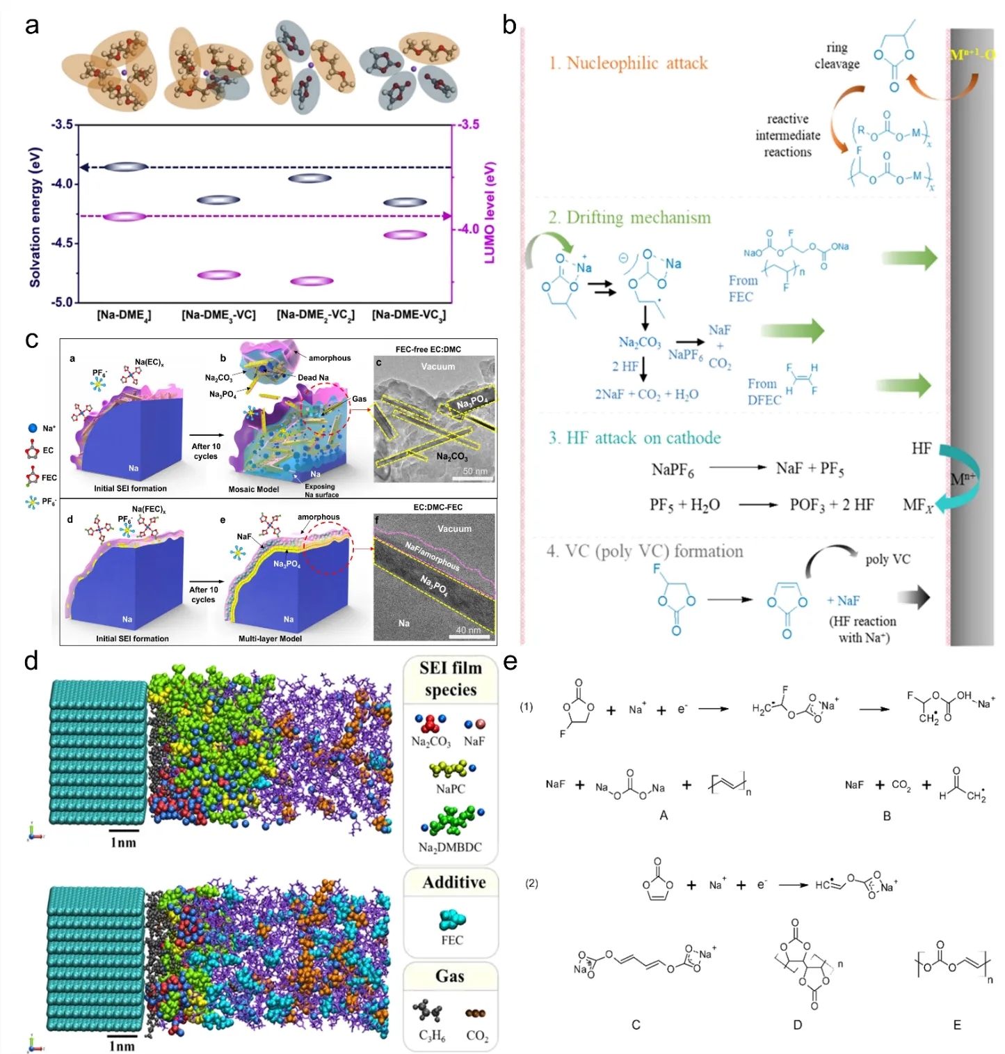
31]. The combination of theoretical calculations and experimental results indicates that the addition of VC to the DME-based electrolyte system can lead to a reduction in the lowest unoccupied molecular orbital (LUMO) energy level of the DME solvation configuration (a), thereby slowing down electrolyte decomposition and maintaining fast Na
+ ion kinetics during continuous charge/discharge processes. In the DME-0.5% VC electrolyte, the SEI films are thinner (<10 nm) and fewer inorganic products, such as Na
2CO
3 and NaF, are produced compared to the DME-based electrolyte after 2000 cycles. VC-derived components like polymeric species -(OCO
2CH-CH)
n- and/or -(CHOCO
2CH)
n- exist in the passivation layer, effectively shielding hard carbon electrodes and enabling ultra-stable cycling behavior with a remarkable capacity retention of 95.6% and a high capacity of 211 mAh·g
−1 after 2000 cycles at 1 A·g
−1. Although VC enhance the performance of most SIBs, its structure containing double bonds makes it prone to oxidation under low voltage. Excessive addition may lead to an increase in SEI film thickness and a subsequent increase in internal resistance of the battery. Therefore, in practical applications, excessive addition (such as 4 wt%) of VC may increase battery polarization and reduce cycling performance [
30]. Furthermore, VC aids in preventing the leaching of metal ions from high voltage cathodes [
30]. Shi et al. added 5% VC to a 1 mol·L
−1 NaCF
3SO
3-Diglyme (DGM) electrolyte system [
25]. Using this modified electrolyte, they assembled a FeS@C||Na
3V
2(PO
4)
3 (NVP)@C full cell, which exhibited excellent cycling performance with a capacity retention of 67% after 1000 cycles at 0.5 C. Notably, there was no need for pre-activation of cathode or anode in their preferred electrolytes. The addition of VC, due to its similar highest occupied molecular orbital (HOMO) level to that of DGM, can synergistically oxidize with DGM, forming a complete and continuous cathode-electrolyte interface on the NVP@C cathode. This effectively enhances the oxidative stability of the electrolyte, preventing electrolyte decomposition.
FEC is a commonly used carbonate additive due to its excellent film-forming performance. Nimkar et al. demonstrated the good performance of FEC on the Na0.44MnO2 (NMO) cathode [
32]. NMO/Na cells containing PC + 2% FEC achieved a better capacity retention of 95% after 250 cycles and significantly smaller Rct values after 100 cycles than the cells without FEC. According to mechanistic insights and analytical characterizations (b), FEC interacts with the alkaline sodium and manganese oxide to generate HF and transform into VC. This VC compound tends to polymerize on the cathode surface and participate in the formation of the CEI. In the study conducted by Dahbi et al., it was observed that HC electrodes exhibited remarkable capacity retention with reversible capacity of 250 mAh·g
−1 when utilized in PC-based electrolytes containing NaPF
6 and FEC [
33]. The simultaneous utilization of NaPF
6 salt and FEC additive creates a synergistic effect that enhances the passivation of the hard-carbon electrode, ultimately improving its cycle performance. Shipitsyn et al. investigated the positive impact of FEC on the lifespan of Na
0.97Ca
0.03[Mn
0.39Fe
0.31Ni
0.22Zn
0.08]O
2 (NCMFNZO)/HC full cell [
34]. The addition of 5 wt% FEC resulted in a remarkably consistent capacity maintenance of around 90% after 200 cycles up to 4 V at 40 °C. Purushotham et al. discovered the key reason why FEC is superior to Trans-difluoroethylene carbonate (DFEC) as an additive through theoretical calculations that due to higher activation energy barriers, DFEC has slower decomposition rates than PC and FEC [
35]. Additionally, DFEC does not produce NaF components during decomposition, while FEC does. Han et al. studied the influence of FEC additives on the structure of the SEI film formed on the sodium metal electrode [
36]. Without FEC addition, the sodium metal electrode reacted with the carbonate electrolyte containing NaPF
6 to form an unstable SEI film characterized by high levels of Na
2CO
3 and Na
3PO
4 (c). This SEI film had a detrimental effect on the cycling process, leading to continuous consumption of sodium from the cathode. The introduction of FEC resulted in the formation of a multilayer SEI film structure (~30 nm) formed on the sodium metal electrode. The resulting structure exhibited an outer layer primarily composed of amorphous NaF and an inner layer with a high concentration of Na
3PO
4. The formation of this layered structure provided stabilization to the SEI film, effectively preventing any additional reactions between the electrolyte and the sodium metal. This phenomenon is consistent with what Purushotham et al. demonstrated [
35].
Like VC, too much FEC can damage battery performance. According to Bouibes et al., the addition of a small quantity of FEC contributes to the enhancement of battery performance [
37]. However, an increase in the FEC content has been found to have a detrimental effect on battery performance, leading to degradation. To understand the microscopic mechanism of this phenomenon, the Red Moon method was employed to investigate the relationship between FEC concentration and the formation of solid SEI film in PC solutions (d). Calculations revealed that the averaged fractional accessible volume (FAV) dropped to 3 vol % in the low FEC concentration range. This reduction led to the formation of denser SEI film structures. Additionally, it was observed that the value of atomic potential energy, ΔV
org, which represents the stability of the SEI film, reached its minimum at 1 vol % of FEC additive, indicating maximum stability. However, as the FEC concentration increased beyond this optimal point, ΔV
org notably increased, indicating a decrease in the stability of the SEI film. With increasing FEC content, insufficient formation of organic dimers between monomers leads to decreased film stability, resulting in reduced battery life during charge and discharge cycles. Yi et al. found that while the addition of FEC to NaPF
6-DME electrolyte reduces irreversible capacity and enhances cathode stability, FEC reacts strongly with the Na electrode, leading to an unstable SEI film and increased interfacial resistance [
38]. To address this, they developed a new low-flammability electrolyte (NaPF
6-FRE) with 1M NaPF
6 in DME, FEC, and 1,1,1,3,3,3-hexafluoroisopropylmethyl ether (HFPM) in a 2:
1:2 volume ratio. The inclusion of HFPM led to the discovery of -CH
2CF
2- and a reduction in Poly(VC), suggesting that the newly formed organic compound -CH
2CF
2- and excess NaF from FEC and HFPM may contribute to the formation of a stable SEI on the Na surface. This electrolyte, boasting a wide electrochemical window of 5.2 V, aimed to stabilize the Na electrode surface in the NVP/Na half-cell by forming a new organic layer containing fluorine. The NVP||Na cell with NaPF
6-FRE electrolyte exhibited superior cycling performance, retaining 94% capacity and achieving an average Coulombic efficiency of 99.9% after 2000 cycles at 5 C.
The combination of VC and FEC can often bring better performance to the battery. Dahbi et al. found that when VC and FEC were added simultaneously to a NaPF
6 electrolyte system, FEC was preferentially reduced to form a polycarbonate sodium compound containing NaF, other components, and polyene compounds, while VC was reduced to form CHCHOCO
2− to stabilize Na
+ ions (e) [
39]. Kumar et al. investigated the decomposition mechanism of additives by quantum chemical simulation [
40]. They focused on studying the decomposition pathways of VC and FEC molecules in an ethylene carbonate (EC) solvent and examined their impact on the composition of the SEI film. The study showed that VC and FEC molecules in SIBs have significant low decomposition barriers and therefore preferentially decompose.
. (
a) The solvation energy and LUMO energy levels of solvated complexes in DME–based and VC–containing electrolytes were compared, and the relevant molecular structures are depicted in the figure. The atoms/ions of C, O, H, and Na are represented in gray, red, white, and purple, respectively. The orange and cyan ellipses serve as substrates for DME and VC molecules, respectively. Reproduced with permission of Ref [
31], Copyright 2020 Elsevier; (
b) The figure illustrates the possible potential mechanisms for the formation of cathodic passivation/surface layers. These include: 1. Nucleophilic attack originating from basic active cathodes. 2. Migration of reduced species from anodes, followed by deposition onto the cathode surface. 3. Interaction between HF and exposed cathode surfaces, leading to the formation of metal fluorides. 4. Formation of VC (poly VC). Reproduced with permission of Ref [
32], Copyright 2020 American Chemical Society; (
c) The schematic drawings in the figure depict the formation of SEI film during cycling, showing the initial nucleation of SEI at the first cycle and the final structure of SEI at the tenth cycle. Additionally, cryo-TEM images of the SEI film after ten cycles are provided for comparison between FEC-free EC: DMC and EC: DMC-FEC electrolytes. Reproduced with permission of Ref [
36], Copyright 2021 Nature; (
d) The figure displays a representative image of SEI films along with the NaPF
6/PC electrolyte solution. Two different concentrations of FEC additive, 1 vol% and 10 vol%, are included in the electrolyte. The solvent, PC, is represented by the color purple, while the gas molecules, namely C
3H
6 and CO
2, are depicted using stick models in gray. Reproduced with permission of Ref [
37], Copyright 2018 American Chemical Society; (
e) The proposed reduction reactions for (1) FEC and (2) VC. Reproduced with permission of Ref [
39], Copyright 2016 American Chemical Society.
Sulfur-containing additives have a narrower electrochemical window as compared to their carbon-based counterparts. This is because the more electronegative sulfur element replaces the carbon element in the carbonate molecule. As a result, sulfur-based additives like sulfites and sultones have the ability to produce SEI films containing sulfur components at both cathode and anode during cycling [
41]. Organic sulfur chemistry is rich, and different types of additives can be tailored to specific application scenarios to increase battery performance, making it a widely researched film-forming additive [
14,
42,
43].
1,3-propane sultone (PS) has excellent effects in inhibiting gas production and improving high-temperature performance, so it is introduced into the electrolyte and has been widely used. Zhang et al. found that adding PS or DTD to the electrolyte resulted in enhanced capacity retention in Na(Ni
0.4Mn
0.4Cu
0.1Ti
0.1)
0.999La
0.001O
2 (NMCT-La)/HC full cell configurations [
15]. The addition of 2 wt% PS or 2 wt% DTD to the base electrolyte (1 M NaPF
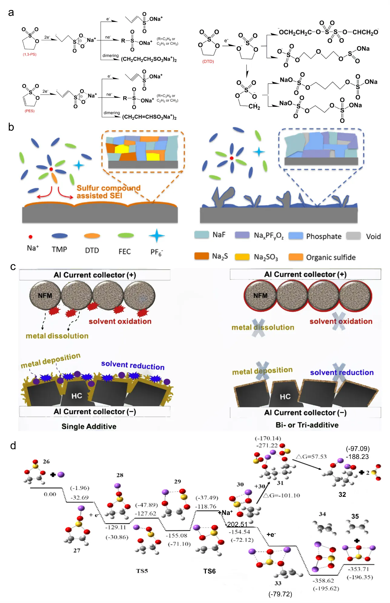
6 in EC:DMC with 2 wt% FEC) demonstrated an enhanced capacity retention rate, increasing from 58.7% to 82.0% and 79.4%, respectively. Sulfates and bisulfates are formed during the decomposition of PS or DTD, which can contribute to the stabilization of the SEI film. This stabilization effect has been observed to result in high-performance and long-life SIBs. The possible reaction paths for the reduction of PS, prop-1-ene-1,3-sultone (PES), and DTD in SIBs are similar to those observed in LIBs (a). Theoretical calculations were employed to analyze the formation of the SEI film during these reduction processes. Liu et al. conducted a study where they investigated the reduction mechanism of PS additives in SIBs using theoretical calculations [
41]. The research suggests that PS additives present in the electrolyte tend to form organic components in the anode SEI film through a single electron reduction mechanism.
DTD, when used as an electrolyte additive, exhibits several beneficial effects on battery performance. It effectively inhibits the initial capacity decline, enhances the initial discharge capacity, reduces volume expansion of the battery after high-temperature exposure, and improves the charge and discharge performance as well as the cycle life of the battery. Zhu et al. found that incorporating a non-flammable electrolyte with DTD leads to the in-situ generation of a stable SEI film with a thickness of approximately 800 nanometers (b) [
44]. This SEI film effectively suppresses side reactions, inhibits dendrite growth, and exhibits integrity, robustness, and low interfacial resistance. In Na||Na symmetric cells, repeated plating/stripping cycles were conducted for over 1350 h at 1 mAh·cm
−2. Furthermore, the full cell employing Prussian Blue (PB) as the cathode demonstrated prolonged cycling stability, achieving 1850 cycles with 88% capacity retention. The stability of the SEI film is attributed to the synergistic effect of multiple components, including sulfur-containing compounds (Na
2S, Na
2SO
3, and organic S-containing salts), NaF, and phosphate (Na
3PO
4), organic sulfide is beneficial to facilitate Na
+ ion transport to reduce interfacial resistance and suppress Na dendrite formation. Additionally, Che et al. found that the addition of 1,3-propene sultone (PST) and DTD to NaNi
1/3Fe
1/3Mn
1/3O
2 (NFM)/HC full cell significantly enhances battery capacity retention [
14]. Full cells with a single additive of FEC only retain 76.6% of their capacity after 750 cycles. In contrast, electrolytes with dual additives of FEC-PST and triple additives of FEC-PST-DTD achieve capacity retentions of 84.4% and 92.2% after 1000 cycles, respectively. Experimental results indicate that PST and DTD contribute to the formation of an organic compound-rich SEI film on the anode side and a dense and thick CEI film on the cathode side, which prevents transition metal ions from dissolving into the electrolyte (c).
In addition to the aforementioned sulfur-containing additives, Ruiz-Martínez et al. have reported that the inclusion of SO
2 and sulfolane as additives in organic electrolytes can modify the interface between sodium and electrolyte, leading to a more robust sodium plating/stripping process [
45]. Liu et al. conducted a study where they investigated the reduction mechanism of ES additives in SIBs using theoretical calculations (d) [
41]. The research suggests that ES additives present in the electrolyte tend to form organic components in the anode SEI film through a single electron reduction mechanism. Similarly, Zhong et al. found that incorporating ES as an additive improves the cycle-life and capacity retention of Na/NVP batteries, even at low temperatures of −40 ℃ [
16]. Specifically, the Na||Na symmetric battery demonstrated a stable cycle of 1500 h, while the Na/NVP battery retained 88.2% of its capacity after 200 cycles at −40 ℃. Theoretical calculations and experimental findings indicate that ES reduces the desolvation energy of sodium ions and facilitates the formation of Na
2S, Na
3N, and Na
2SO
3-rich SEI on the surface of sodium. In the future, computer-aided theoretical calculation for high-throughput screening can be employed to facilitate the advancement of sulfur-based additives for battery use, which is an important way to improve research and development efficiency [
46,
47,
48].
. (
a) Potential reaction pathways for the reduction of 1,3–PS, PES, and DTD in SIBs. Reproduced with permission of Ref [
15], Copyright 2022 Elsevier; (
b) Illustration comparing the structure of the SEI film formed in a TMP/FEC/DTD electrolyte with that formed in a TMP/FEC electrolyte. Reproduced with permission of Ref [
44], Copyright 2021 Elsevier; (
c) A diagram summarizing the involvement of PST and DTD additives in the HC/NFM full cell. Reproduced with permission of Ref [
14], Copyright 2018 Elsevier; (
d) Schematic illustrating the potential energy diagram depicting the mechanism of ES in a battery system. Reproduced with permission of Ref [
41], Copyright 2016 Wiley.
Silicon-containing additives are mainly composed of silicone oxide structures, whose Si-O bonds are prone to breaking and thus show high reactivity. These additives are capable of undergoing selective reduction in the electrolyte, effectively suppressing the decomposition of other components in the electrolyte. Currently, silicon-containing additives are widely employed in lithium-ion batteries. According to literature reports, they have good film-forming properties on the cathode and form a dense and uniform SEI film [
49,
50,
51].
Cometto et al. have reported that the addition of tris(trimethylsilyl)phosphite (TMSPi) and sodium bis(oxalato)borate (NaODFB) to a 1M NaPF
6 in EC-DMC (1:1 v/v ratio) solution can enhance the high temperature performance of Na
3V
2(PO
4)
2F
3 (NVPF)/C full cells in terms of cyclability and self-discharge in SIBs [
52]. Experimental results demonstrate that NaODFB primarily governs the formation of the SEI film while TMSPi effectively mitigates O
2 generation and other parasitic, deleterious, and acid-boosted processes occurring at higher potentials and contribute to the generation of adsorbed RO− (where R = -alkyl or -H). Furthermore, TMSPi aids in regulating the formation of the SEI film by NaODFB and its growth during cycling. Similarly, Chen et al. have discovered that the incorporation of low levels of N,N-diethyltrimethylsilylamine (DETMSA) as an electrolyte additive in NaMnO
2/HC full cells can enhance the lifespan of SIBs by chemically scavenging H
2O and HF [
53]. The presence of DETMSA aids in the formation of a more robust and less resistive passivation surface layer for the SEI film, with the diethylamino group increasing the HOMO energy of the molecules, thereby being preferentially oxidized while the trimethylsilyl group has no negative effect.
The greater ionic size of Na
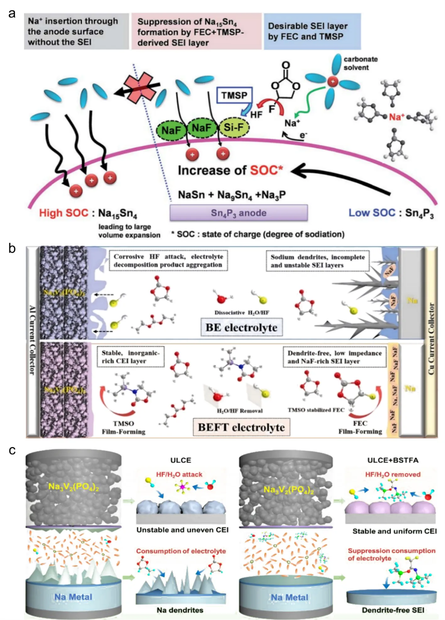
+ in comparison to Li+ is a crucial factor affecting the reversibility of Na insertion/extraction in Na host materials. Jang et al. discovered that incorporating FEC with TMSPi enhances both the cycle stability of Sn4P
3/Na cells and the desodiation kinetics of Sn4P
3 anodes [
54]. After 50 cycles, the Sn
4P
3 anodes using the FEC+TMSP-added electrolyte demonstrated a Na extraction capacity exceeding 500 mAh·g
−1, while the anodes without the additive exhibited a lower capacity of less than 250 mAh·g
−1. This combination of binary additives serves to protect the Sn
4P
3 anode by preventing the formation of ether and Na
2CO
3 by EC decomposition and the generation of the Na
15Sn
4 compound. The Na
15Sn
4 phase is known for its significant increase in volume during the process of Na insertion (sodiation). Furthermore, the inclusion of TMSPi additive effectively reduces the presence of HF resulting from FEC decomposition. This reduction helps reduce the occurrence of a significant portion of NaF formation and promotes the development of a more stable and robust SEI film (a). However, it should be noted that these protective effects may not be sufficient in inhibiting sodium dendrite formation as well as electrolyte erosion. Liu et al. developed a multifunctional additive called 3-Trimethylsilyl-2-oxazolidinone (TMSO), which serves multiple purposes in sodium batteries [
55]. In addition to removing H
2O and HF from the electrolyte, TMSO also prevents the degradation of NaPF
6 as well as improves the robustness of FEC-containing electrolytes. Additionally, TMSO facilitates the formation of a stable CEI film on the surface of the NVP cathode. This CEI film reduces NVP cracking, structural pulverization, and interfacial resistance, leading to improved long-term cycling stability (b). To address the limited cycle life and rate performance caused due to the pronounced reactivity of sodium metal anodes in ultralow-concentration electrolytes (ULCE), Jiang et al. introduced a compound containing acetamide called N,O-bis(trimethylsilyl) trifluoroacetamide (BSTFA) [
56]. By incorporating BSTFA into a ULCE solution containing 0.3 M NaPF
6 in EC/PC (1:1 vol%), the electrolyte was stabilized, leading to the formation of a highly conductive interface in Na||NVP batteries (c). This resulted in the development of protective interface layers on the sodium metal anode and NVP cathode. As a result, the Na||NVP battery incorporating 2% BSTFA in the ULCE solution showed an impressive capacity retention rate of 92.63% after undergoing 1955 cycles at 2 C. Additionally, it showcased outstanding rate capability by achieving a rate exceeding 105 mAh·g
−1 at 40 C. Unsaturated double bonds (C=N) from BSTFA can trigger electrochemical polymerization, forming free radical cations that polymerize with carbonate organic solvents to create a stable and solid SEI film. Both density functional theory (DFT) calculations and experimental data indicated that BSTFA can increases the content of NaF, effectively remove HF and H2O in the electrolyte containing NaPF
6, suppress the degradation reaction of NaPF
6 through hydrolysis, and form protective boundary films on both the sodium metal anode and NVP cathode.
. (
a) A diagram illustrating the role of the NaF-based SEI film formed during the sodiation process. Reproduced with permission of Ref [
54], Copyright 2015 The Royal Society of Chemistry; (
b) A schematic illustrating the mechanism of action of the multifunctional TMSO additive in SMBs. Reproduced with permission of Ref [
55], Copyright 2022 Elsevier; (
c) The proposed reaction mechanisms of the BSTFA additive in SMBs. Reproduced with permission of Ref [
56], Copyright 2021 Elsevier.
The safety of SIBs is a significant challenge, due to the combustible nature of the organic carbonate electrolytes and carbon anodes currently used. One of the most convenient and effective approaches to addressing this safety issue is to develop safer electrolytes. Organic phosphates have emerged as promising candidates for safer electrolytes in SIBs. Organic electrolyte with phosphate additives present several advantages over ionic liquids and solid-state electrolytes when compared. They exhibit reduced viscosity, thereby improving the ion conductivity within the electrolyte. Additionally, they have a wider liquid temperature range, making them suitable for a variety of operating conditions. Moreover, organic phosphates possess greater salt-dissolving ability, enabling efficient ion transport within the battery system. They have been employed as co-solvents or additives to enhance flame retardancy in LIBs, demonstrating their potential for improving the safety characteristics of battery systems [
57,
58,
59].
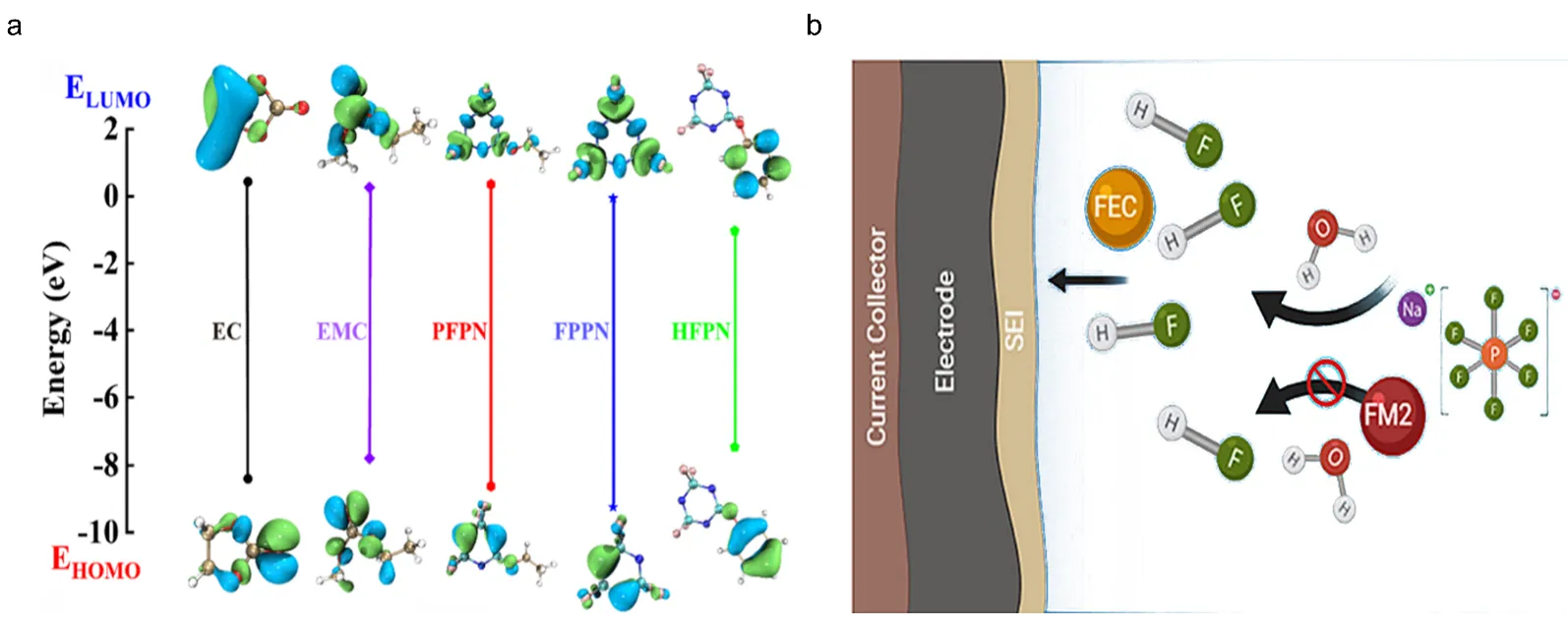
Composite flame-retardant additives containing phosphazene compounds have shown promise in boosting flame retardance and augmenting compatibility with electrode materials. However, compared to phosphates, their effectiveness in suppressing flammability is relatively lower. To improve their flame retardancy and electrochemical compatibility, fluorine atoms can be introduced. Several phosphazene additives, such as (ethoxy)-pentafluorocyclotriphosphazene (PFPN), hexafluorocyclotriphosphazene (FPPN), and pentafluoro(phenoxy)cyclotriphosphazene (HFPN), have been reported for use in LIBs [
60,
61] (a). By incorporating fluorine atoms, these additives demonstrate improved flame retardancy and compatibility with the LIB system. Building on prior research, ethoxy(pentafluoro)cyclotriphosphazene (EFPN) was chosen as a flame-retarding additive for SIBs due to its favorable characteristics. Feng et al. discovered that as the EFPN content increased from 0 to 5 wt%, the self-extinguishing time (SET) of the electrolyte decreased from 58 s to 0 s [
62]. The incorporation of 5% EFPN enhanced the cyclability of both the acetylene black (AB) anode and the NMO cathode in sodium-ion batteries. Specifically, the AB/Na half-cell preserved nearly 100% of its initial capacity after 200 cycles, while the Na
0.44MnO
2/Na half-cell maintained its capacity after 50 cycles at a rate of 20 mA·g
−1. The fluorine-rich structure of EFPN likely contributes to the formation of a stable interface between the electrolyte and electrode. Furthermore, another electrolyte additive called 2,2,2-trifluoroethoxy-2,2,2-ethoxy phosphazene (FM2) has been reported by Barnes et al [
63]. This additive acts as an HF "scavenger" and helps enhance the long-term stability of electrolytes that may be exposed to or contain water, thereby extending their shelf life (b).
. (
a) The HOMO and LUMO energy levels of EC, EMC, PFPN, FPPN, and HFPN. Reproduced with permission of Ref [
60], Copyright 2021 American Chemical Society; (
b) Working mechanism of FM2. Reproduced with permission of Ref [
63], Copyright 2020 Elsevier.
The use of rubidium and cesium salts as electrolyte additives has been explored to enhance the cycling efficiency of lithium and graphite anodes in LIBs [
64,
65]. Che et al. investigated the use of rubidium and cesium ions as electrolyte additives in SIBs [
66]. The results showed that the addition of 0.05 M of MPF
6 (M = Rb or Cs) into the electrolyte had a substantial impact on the chemical composition of the SEI film formed on the HC electrode surfaces (a). This resulted in a notable improvement in the ionic conductivity and stability of the SEI film, leading to enhanced capacity retention of the sodium/hard carbon cells. A new low-cost electrolyte additive, nano H-ZSM-5 zeolite (NZeo), has been developed by Chen et al. for SIBs [
67]. The addition of NZeo has been proven to extend the cycle life of NaMO
2/HC full cells by absorbing small molecules into the stable framework structure of the zeolite (b). The encapsulation of water, CO
2, HF, and other byproducts of electrolyte decomposition within the zeolite cages results in a more compact and enduring composition of the SEI film, improving the interface stability throughout the lifetime of the cell. Moeez et al. achieved the form of a thick and robust CEI film by incorporating functional additives, Na
2CO
3 and NaF, effectively modifies the CEI layer of Na
0.67Fe
0.5Mn
0.5O
2 (NFMO) to predominantly consist of durable Na
2CO
3 and NaF (c) [
68]. The newly created CEI film proved to be highly effective in mitigating the leaching of transition metals into the electrolyte, which in turn prevented the degradation of the solid interphase layer. This successful application of the additives effectively resolved the capacity fading issue observed during electrochemical cycling of NFMO electrodes. NFMO electrodes without additives in the electrolyte show a capacity retention of around 18.6% after 500 cycles. However, incorporating functional additives like 2% Na
2CO
3 and 2% NaF in the electrolyte boosts the capacity retention of NFMO electrodes to 36.8% and 33.6% after the same number of cycles, respectively.
LiODFB, a lithium salt and electrolyte additive, has been extensively researched in LIBs due to its ability to form a thin and robust SEI film on graphite electrode surfaces, combining the advantages of LiBOB and LiBF
4. Zhang et al. verified the creation of a SEI film rich in LiF on the HC anode surface in SIBs by incorporating LiODFB additive into a 1 M NaPF
6 electrolyte in EC:DMC (1:1 volume ratio) [
69]. In contrast, the presence of a LiF-rich SEI film poses a challenge to the diffusion of Na
+ ions into the HC electrode. This study, although showcasing a less favorable outcome, sheds light on the constraint of employing lithium compounds with lower solubility as SEI film constituents in sodium-ion batteries. Rather than promoting the transfer of Na
+ ions, these compounds predominantly enhance the transport of lithium ions. Thus, their use as SEI film components in sodium-ion batteries is limited due to the hindrance they pose to efficient sodium ion diffusion. In addition, Yang et al. synthesized sodium difluorophosphates (NaDFP) salt through the ion exchange of potassium difluorophosphate (KDFP) and NaPF6 [
70]. The presence of NaDFP facilitated the formation of stable Na
+ ion-conducting SEI film components with higher NaF content, leading to improved cycling performance of the HC electrode. In comparison to the plain electrolyte, the HC electrode with NaDFP showed improved performance, including higher capacity retention (76.3% after 500 cycles versus 59.2% after 200 cycles), a high average coulombic efficiency of 99.9% over 500 cycles in Na/HC cells, and a notable reduction in interface resistance in HC/HC symmetric cells.
. (
a) Working mechanism of MPF
6 (M=Rb or Cs). Reproduced with permission of Ref [
66], Copyright 2017 Elsevier; (
b) Nano-zeolilte ZSM-5 electrolyte additive stabilizes the HC electrolyte interface for SIBs. Reproduced with permission of Ref [
67], Copyright 2020 The Royal Society of Chemistry; (
c) The figure illustrates the various CEI layers formed on the surfaces of NFMO electrodes. It shows images of the original CEI layer formed without additives (NFMO-w/o additives) and the modified CEI layer achieved through the inclusion of Na
2CO
3 and NaF additives. Reproduced with permission of Ref [
68], Copyright 2021 Elsevier.
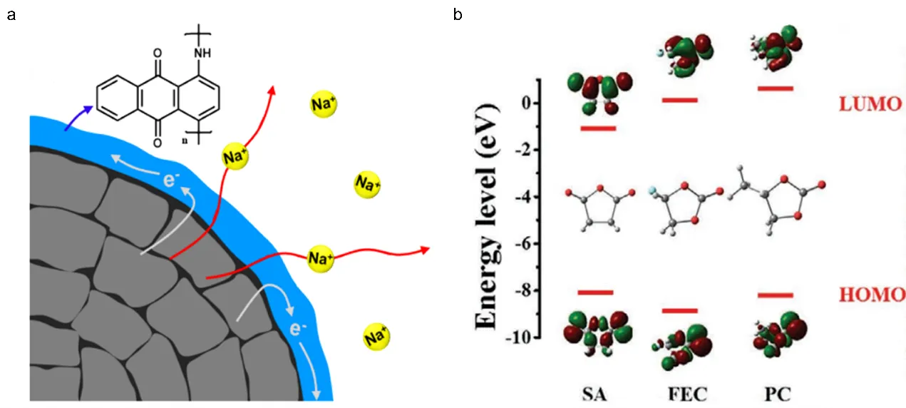
In addition to the above types of electrolyte additives, other commonly used types include anthraquinone, acid anhydrides, nitriles, biphenyls and amine among which their effects have been reported in literature. Park et al. introduced an innovative electrolyte additive known as 1-aminoanthraquinone (AAQ) to serve as a film-forming agent [
71]. This study represented a pioneering achievement in the in-situ generation of an electronically-conductive polymer on NVPF material for SIBs. To accomplish this, a minute quantity of AAQ was incorporated into a liquid electrolyte as an additive that could undergo electro-polymerization. Undergoing electrochemical oxidation, AAQ underwent an in-situ transformation, forming a poly(1-aminoanthraquinone) (PAAQ) layer on the surface of the NVPF cathode material. The resulting conductive PAAQ layer effectively mitigated interfacial resistance and suppressed the oxidative degradation of the electrolyte during cycling (a). In a novel approach, Fan et al. investigated the use of succinic anhydride (SA) as a filming additive in sodium-ion batteries (b) [
72]. The research findings highlighted the significant improvement in the durability of the Na/Na
0.6Li
0.15Ni
0.15Mn
0.55Cu
0.15O
2 (NLNMC) cell with the addition of SA. This improvement was attributed to the promotion of uniformity and stability in the interphase layer formed on the cycled NLNMC material. As a result, the NLNMC cell exhibited a remarkable capacity retention of 87.2% over 400 cycles at a 1 C rate. This enhancement was further explained by the presence of more oxygen-rich organic species and reduced levels of NaF. The incorporation of SA not only had a notable impact on the interphase layer in the sodium anode but also resulted in a reduction in the overall generation of CO
2, a byproduct of electrolyte decomposition. This reduction in CO
2 generation is advantageous for improving battery safety and facilitating practical applications. Based on frontier molecular orbital energy calculations, it has been determined that adiponitrile (ADN) possesses a higher electron-donating capability compared to carbonate solvents. Consequently, ADN exhibits enhanced reducibility on the cathode material surface, facilitating the formation of a SEI film. Song et al. selected ADN as an electrolyte additive for the first time to improve the discharge capacity and capacity retention of a Na
0.76Ni
0.3Fe
0.4Mn
0.3O
2||HC full cell [
73]. ADN played a crucial role in promoting the generation of NaF within the SEI film, while also leading to the formation of NaCN as essential components of this protective film.
However, safety issues such as overcharge may be a major impediment to the widespread use of SIBs. To address safety concerns associated with overcharging in battery systems, researchers have developed and incorporated various additives. One such additive is the aromatic compound biphenyl (BP), which is widely used as an overcharge protection additive in commercial LIBs. Feng et al. made an interesting discovery that BP can undergo electro-polymerization at 4.3 V (vs. Na/Na
+), effectively safeguarding NMO/Na batteries from voltage runaway during overcharging [
74]. This electro-polymerization process consumes the excess charge current, resulting in a remarkable increase of over 800% in the overcharge capacity. Remarkably, the addition of 3% BP to the battery system has minimal impact on cycling performance and capacity. Therefore, BP shows great potential as an overcharge protection additive in SIBs.
Ideally, an effective redox shuttle needs to offer reliable protection against high overcharge currents while requiring a minimal additive amount. Trisaminocyclopropenium perchlorate (TAC·ClO
4) is an ionic compound characterized by its tiniest aromatic ring structure, enabling rapid diffusion, excellent solubility, and exceptional chemical and electrochemical stability in both redox states. Ji et al. found that by using just 0.1 M TAC·ClO
4 in the electrolyte, the NVP cathode displayed the capability to sustain overcharge current up to 10 C or 400% SOC [
75]. The NVP/HC cells exhibited robust resistance to overcharging, demonstrating 176 cycles at a 0.5 C rate and 54 cycles at a 1 C rate with 100% overcharge. Additionally, the inclusion of TAC had minimal impact on the electrochemical performance of the SIB. This redox shuttle effectively mitigates the risk of overcharge by facilitating the transfer of charge and maintaining stable electrode potentials. Its use demonstrates promising potential for enhancing the safety and reliability of battery systems under high overcharge conditions.
. (
a) A schematic illustration depicting the enhancement of the electrochemical performance of the NVPF cathode by the formation of a conductive PAAQ layer. The blue arrow signifies the primary component of the thin PAAQ layer, the white arrow denotes the thin PAAQ layer’s role as the electron pathway during charge and discharge cycles, and the red arrow indicates the pathway for Na
+ ion transfer. Reproduced with permission of Ref [
71], Copyright 2020 Elsevier; (
b) The HOMO and LUMO levels of SA, FEC, and PC. Reproduced with permission of Ref [
72], Copyright 2021 Wiley.
An electrolyte is an important component of a battery, and the use of additives in it directly affects the improvement of battery performance. Therefore, this article reviews the research progress on different types of additives in sodium-ion battery electrolytes in recent years, including unsaturated carbonate, sulfur compounds, silicon compounds, phosphorus compounds, inorganic salts, and other additives. Furthermore, a detailed analysis from the perspective of film formation was conducted to investigate the influence of various types of electrolyte additives on the performance of SIBs. Finally, the following suggestions are proposed for the future development of additives in sodium-ion battery electrolytes.
3.1. Calculation Assistant Method for Screening New Sodium-Ion Battery Electrolyte Additives
Currently, DFT has been widely applied in various fields, including the prediction of the redox capability of various types of electrolyte additives by analyzing the HOMO/LUMO energy levels and redox potentials. Additionally, the potential energy calculations of possible intermediates can be carried out using the DFT method to explore the reaction pathway during the decomposition process and obtain potential decomposition products. Recent research has unveiled the influential role of the surrounding electrolyte environment, encompassing electrolyte salts and solvents, on the predictive performance of electrolyte additives. It is crucial to take this into account when establishing correlations between computational findings and experimental observations. Moreover, the integration of multiscale calculations spanning from nanoscale to macroscopic levels, along with emerging data-driven techniques like machine learning, with quantum chemical calculations holds the potential to expedite the design and screening of electrolyte additives for SIBs. This approach enables more efficient and targeted exploration of electrolyte additive candidates.
3.2. Understanding the Profound Correlation between Structure and Performance of Electrolyte Additives in SIBs
While some correlations between the structures of electrolyte additives and the performance of SIBs have been explored, there are still many unexplored associations between additive structures and SIBs performance. Therefore, further research is necessary to understand the correlation between the structures and performance of additives. Through the aforementioned studies, it is possible to fill the knowledge gaps regarding the profound correlation between additive structures and performance in SIBs.
3.3. Multiple Electrolyte Additives Compound Used in SIBs
When a single type of additive is used in SIBs, satisfactory performance is often not achieved. However, by combining two or more additives, higher performance can be attained in practical production. Therefore, it is necessary to study the combination of electrolyte additives in SIBs to gain a deeper understanding of their synergistic effects.
This work was supported by the Guangdong Province Natural Science Foundation (2023A1515011122).
Conceptualization, Z.Z. and Z.F.; Methodology, J.L.; Validation, Z.Z., Z.F. and J.L.; Formal Analysis, Z.Z.; Investigation, H.H. and H.Z.; Resources, J.L.; Data Curation, Z.L. and J.L; Writing-Original Draft Preparation, Z.Z. and Z.F.; Writing-Review & Editing, J.L.; Visualization, X.Z.; Supervision, J.Z.; Project Administration, H.H.
Not applicable.
Not applicable.
This research was funded by the Guangdong Province Natural Science Foundation (2023A1515011122).
The authors declare that they have no known competing financial interests or personal relationships that could have appeared to influence the work reported in this paper.